
Subscribe to Our Youtube Channel
Related Manuals for Digitus professional DS-72210


Summary of Contents for Digitus professional DS-72210
- Page 1 LCD KVM SWITCH Manual DS-72210 DS-72211 DS-72212 DS-72213 DS-72214 DS-72216 DS-72217...
-
Page 2: User Precautions
User Precautions The manufacturer has the right to modify and alter the information, documentation and specifications contained in this manual without prior notice. Manufactures makes no warranty, express, implied or statutory, disclaims or specifically disclaims its possibility of sale and applicability for a particular purpose. The same applies to any sold and authorized manufacturer's software described in this manual. -
Page 3: Product Model Description
Product Model Description Configuration instructions 17 inch 4: 3 VGA LCD Console (LCD screen, keyboard and mouse), DS-72210 No KVM module 19 inch 16: 9 VGA LCD Console (LCD screen, keyboard and mouse), DS-72211 No KVM module DS-72212 1 Port VGA KVM module cable... -
Page 4: Package Contents
Package Contents The LCD Console package includes the following: (DS-72210/DS-72211) 1x LCD console 1x User manual 2x Mounting bracket 2x Lock ear 2x Install screws 1x Power adapter 1x power cable The KVM module package includes the following:... -
Page 5: Table Of Contents
Contents User Precautions ..................................2 Product Model Description ............................... 3 Package Contents ..................................4 About this manual ..................................7 Description of Terms .................................. 8 Chapter 1 ....................................9 Introduction ....................................9 Product Introduction ................................. 9 Product Features ................................10 Hardware Requirements ..............................11 KVM module ................................ - Page 6 Chapter4 ....................................39 OSD Operation ..................................39 OSD Introduction ................................39 OSD Log in ..................................39 OSD Hot-Key ..................................39 OSD Main Menu ................................40 OSD Main Screen Headings ............................. 40 OSD Function ................................... 41 F1 GOTO: .................................. 41 F2 SCAN: .................................. 42 F3 LIST: ..................................
-
Page 7: About This Manual
About this manual This User's Guide will assist you in the effective use of the product features, including the installation, setup and operation of the equipment. You will find the following in this manual: Chapter 1 Introduction - This chapter introduces the Rack KVM device system, including its functions, features, and advantages, and describes and introduces the front and rear panel components. -
Page 8: Description Of Terms
Description of Terms Symbol Indicates the text information that should be entered [ ] The parentheses indicate the keys that need to be entered. For example, [Enter] means to press the Enter key. For keys that need to be entered at the same time, they are placed in the same bracket, and the keys are joined by a plus sign. -
Page 9: Chapter 1
Product Information To find out more about KVM's products and how to use them more efficiently, please visit our website or contact an authorized dealer for more contact information. Chapter 1 Introduction Product Introduction DIGITUS LCD KVM Switch is a computer equipment that allows administrators to control 8/16pcs computers from a set of USB keyboards, mouse, or a set of PS/2 keyboards, mouse. -
Page 10: Product Features
The series of LCD liquid crystal display can be divided into 2 models for you to choose: 17 inch and 19inch. The modular design and installation of the product series, you can freely replace the actual needs of the KVM components to facilitate the free combination of different applications. According to the module type can be divided into 2 categories: VGA cable type, CAT5 connection type. -
Page 11: Hardware Requirements
Hardware Requirements KVM module This LVD Console can work as 1 port LCD console with Single port KVM module cable (DS-72212) (Or) It can work as LCD KVM switch after adding a KVM module behind LCD console. 8 port VGA KVM module (DS-72213) ... -
Page 12: Over Ip Module (Optional)
CAT5 connection Dongle VGA + USB (Type A) Default included in DS-72217 and DS-72218 KVM module Over IP module (optional) Over IP control module “DS-51000-1” is needed to support over IP control (Optional installation) Operation System Operation System Version Windows Windows 2000/XP/2003/2008/Vista/7/10... -
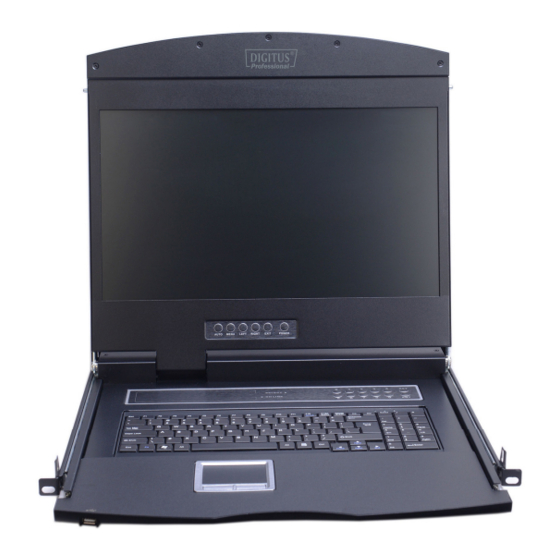
Page 13: Hardware Introduction
Hardware Introduction Front View 17inch 4: 3 LCD Console: Model DS-72210 19inch 16: 9 LCD Console: Model DS-72211... -
Page 14: Rear View
Part Function Description Upper handle Pull the handle, slide the LCD module out and push it in Lock Used to lock the LCD module, pull out the module must first unlock, push into the automatic locking LCD screen cover Can be opened or closed with the handle, opening and closing angle of 0-110 degrees LED screen 17 "or 19"... -
Page 15: Kvm Module
KVM module Single port KVM module cable (DS-72212) LCD Connector DB37P Computer-side VGA + USB (Type A) + PS/2 keyboard (purple) + PS/2 mouse (green) It is needed if no 8/16 KVM module connected to LCD console. 8 Port VGA KVM module (DS-72213) 8 port VGA Rear View (with IP module) ... -
Page 16: Front View Of The 4: 3 Screen And 16: 9 Screen
Front view of the 4: 3 screen and 16: 9 screen: 17inch 4: 3 screen 19inch 16: 9 screen... -
Page 17: Overall Dimensions Of The Lcd Kvm
Overall Dimensions of the LCD KVM LCD Console Dimension: 462.6*445*45mm... - Page 18 LCD KVM Dimension: LCD Console with KVM 8/16 port KVM module 611x445x45 mm...
-
Page 19: Chapter 2
Chapter 2 Hardware Installation Stacking and Installation Precautions Important safety information regarding the placement of the LCD KVM switch is listed in the appendix, please refer to it before proceeding. Before installation, please make sure that all the devices connected to the power supply are turned off. -
Page 20: Single Port Lcd Kvm Cable (Ds-72212)
Single Port LCD KVM Cable (DS-72212) VGA Single port LCD KVM (1 Port KVM module cable: DS-72212) -
Page 21: Kvm Module Installation (Ds-72213, Ds-72214)
KVM Module Installation (DS-72213, DS-72214) This series of LCD screen and keyboard, mouse and the rear part of the KVM part of the components can be demolished separation, this design allows you to change the KVM components, or KVM components damaged KVM components dismantled after the return to the manufacturer for repair and replace. -
Page 22: Cat5 Kvm Module Installation (Ds-72216, Ds-72217)
CAT5 KVM Module Installation (DS-72216, DS-72217) Connect DB 37PIN to LCD Console, similar to VGA KVM module To install a Cat 5 KVM module, refer to the following diagrams and do the following: 1. Plug your USB keyboard and mouse into the USB console port if 2 console needed. -
Page 23: Ip Module Installation (Ds-51000-1)
IP Module Installation (DS-51000-1) If you already have KVM module attached. You can directly purchase the IP module for equipment upgrades and expansion, the operation method is simple and quick, can quickly enhance the integrated management of KVM Application over IP control. 1. - Page 24 4. Remove the extended IP module and push it gently into the recess in the mounting module cavity as shown. 5. After pushing the IP module to the bottom, fix the IP module with the two screws that have been removed before.
-
Page 25: Rack Mount Installation
Rack Mount INSTALLATION Before Use: Make sure all the devices are power off. Built-in mounting bracket installation: The built-in mounting bracket comes with a nut, and the fixing nut is welded inside the bending hole at the top of the bracket. Install the bracket into the cabinet mounting post on the upper cabinet, align the bracket mounting holes with the holes in the cabinet mounting column, and then use the screws to fix. - Page 26 Place the KVM Switch in the installed bracket and secure the KVM Switch, cabinet and mounting bracket.
- Page 27 Mounting and fixing in the bracket tail with Lock Ear and Screws from accessory...
-
Page 28: Computer Device Installation
Screws mounting position instruction Computer Device Installation Note: Before the installation, make sure that the equipment is powered off. To prevent damage to the equipment during installation, make sure that all the devices installed are well grounded. VGA KVM module installation To install a single-level KVM, refer to the following diagrams (numbered in the order of steps on the graph) and do the following: 1. - Page 29 Note: 1. Make sure that all plugs are connected to the same group of KVM connection port jacks (all connected to Port1, or all connected to Port2). 2. IP module is an optional module of the product. If the product you purchased does not contain the module, please ignore the related operation in Step 5.
-
Page 30: Cascade Device Connection
Cascade Device Connection This product can be cascaded to increase the number of control devices, combined with IP remote control mode can be flexibly used in a variety of user environment requirements. 8 Port KVM switch (DS-23200-2) and 16 Port KVM switch (DS-23300-2) are available for cascade expansion. In the VGA switch Cascade mode, the keyboard, mouse and computer connections is same with the stand-alone connection, this part will not repeat them, the number part of the description is as follows: 1. - Page 31 KVM Switch Cascade diagram (8-Port DS-23200-2/16-Port DS-23300-2) Note: Please connect only one of interface from USB or PS/2 (USB is suggested)
-
Page 32: Disassembly Of The Keyboard Module
Disassembly of the Keyboard Module If you need to replace the LCD module part of the keyboard or repair this part, can also be demolished according to the following diagram. 1. The LCD KVM placed in the rack and fixed, the LCD panel turned up, revealing the keyboard, the mouse's operating surface. - Page 33 Note: If you replace the installation, please first plug the keyboard USB interface, then put the keyboard module into the limit slot.
-
Page 34: Chapter3
Chapter3 Basic Operation Hot Plug The KVM switch supports hot-plug, removing and removing components by unplugging the cables connected to the computer's port without shutting down the switch. To make the hot swap function work properly, follow these steps: Hot – Plug Computer Connection In order for OSD Menu to correspond to the KVM connection port changes, you must reset OSD Menu to display the latest connection port information, OSD menu settings. -
Page 35: Switch The Selection Manually
Switch the Selection Manually Use the buttons on the front control panel to select a port. KVM switch button located in the top of the keyboard operating area, divided into three blocks, from left to right in order is the online indicator display area, Port switch to select the display area, Port switch digital button area. -
Page 36: Hotkey Selection
[POWER] Pressing the button allows you to turn the LCD screen on and off LED display for the LCD screen status indicator, you can indicate three working status: red, green, do not show the state. "Red" indicates that the LCD screen has been powered, but no video signal input. -
Page 37: Open Way Of Lcd Screen
Open Way of LCD Screen OPEN CLOSE... - Page 38 When using, the LCD assembly can be unlocked from the side track by the handle of the upper part of the LCD unit. After unlocking, the LCD module can be pulled out from the slide rail. (Refer to the diagram above for operation) ...
-
Page 39: Chapter4
Chapter4 OSD Operation OSD Introduction OSD (On Screen Display), provides a menu driven interface to handle the computer switching procedure to provide instant access to any computer on the installation. OSD Log in The OSD function provides a two-level (administrator/user) password mechanism. The factory default setting is no need to login password authentication, so you are the first time to open the OSD main menu, no need to enter the login password to enter the OSD main menu screen for the corresponding operation. -
Page 40: Osd Main Menu
OSD Main Menu Active OSD, following picture will be shown on the screen: [F1] --- [F6] at the bottom of the screen is the function setting of OSD menu, and corresponding operation and setting of corresponding function by keyboard. ... -
Page 41: Osd Function
OSD Function OSD functions are used to configure and control the OSD. For example, you can: rapidly switch to any port; scan selected ports only; limit the list you wish to view; designate a port as a Quick View Port; create or edit a port name;... -
Page 42: F2 Scan
F2 SCAN: The "SCAN" function allows you to perform automatic port scanning of the connected computers. Users can switch ports in order to view the corresponding port computer status. The SCAN function can automatically scan from current selected port, the scan interval can be set by users. -
Page 43: F4 Qv
F4 QV: QV function can select port as Quick View. Move the highlight bar to a port; press [F4], an icon of up triangle appears. Press [F4] again, the icon disappears. F5 EDIT: EDIT function creates or edits the name of a port. Press [F5], a pink edit box will appear on the screen. Input name, and then press [Enter], the port is set a name and it will also appear on the screen. - Page 44 To change your settings: 1. Move the selection column to this option, press [Enter] to enter a setting option. 2. After selecting an item, the sub-menu and the further options provided will appear. To select it, double-click the mouse or move the selection column to the option, and then press the [Enter] key, an icon will appear.
-
Page 45: Osd Activating Hotkey
OSD ACTIVATING HOTKEY It provides you with four hotkey combinations: You can use the keyboard [↑] [↓] to move cursor to select, and then press [Enter] key to save. The default is to use [CTRL] [CTRL] as the OSD menu start hotkey. SWITCH HOTKEY It provides you with four hotkey combinations: [SCRLL] [SCRLL] [NUM], [CTRL] [CTRL] [NUM], [ALT] [ALT] [NUM], [SHIFT] [SHIFT] [NUM] You can use the... -
Page 46: Scan Duration
SCAN DURATION Duration for scanning one port. Options are 3 seconds, 5 seconds, 10 seconds, 15 seconds, 20 seconds, 30 seconds, 40 seconds, 60 seconds. Move the highlight bar to an option and press [Enter] to select it. SET PASSWORD Set new password. -
Page 47: Clear The Name List
CLEAR THE NAME LIST This function clears the name of a port in the OSD menu. If you use this function, all the port names will be emptied, so please do it carefully. When doing this, you need to verify the password of the administrator, input [Y] key, then press [Enter] to confirm the operation. -
Page 48: Appendix
Appendix Safety Instruction In General This product is for indoor use only. Please read all the instructions for future reference. Follow all the warnings and instructions on the device. Do not place this equipment on any unstable surface (such as cart, stand, table, etc.). If this equipment falls, it will cause serious damage. -
Page 49: Cabinet Installation
The machine can’t be operated normally as instructed by the operating instructions. Adjustment only for the control functions covered by the operating instructions, and other inappropriate operations may cause damage, requiring more qualified personnel to perform repairs Cabinet Installation ... -
Page 50: Specification
Specification LCD Module Specifications Model DS-72210 DS-72211 LCD Display LCD Screen Size Ratio 17inch4: 3 19inch16: 9 Assembly LCD Screen Type SXGA TFT-LCD Wide AHVA TFT-LCD Viewing Area 337.920(H) × 270.336(V) 408.96(H) x 230.04(V) Resolution 1280x1024@60Hz 1366x768@60Hz Support color 16.7M color 16.7Mcolor, True 8 bit... - Page 51 Operating Operating temperature -10-50˚C Environment Storage temperature -20-60˚C Humidity 0-80%RH, No Condensation Physical Housing Metal, Black Dimension 462.6*445*45mm Weight 6.15 6.07 VGA KVM Module Specification Type 1 Port 8 Port 16 Port Model DS-72212 DS-72213 DS-72214 Computer Direct Connects Connection Maximum Cascade Computer Port Selection OSD Menu, Front panel buttons,...
-
Page 52: Warranty Conditions
CAT5 KVM module Specification Type 8 Port 16 Port Model DS-72216 DS-72217 Computer Direct Connects Connection OSD Menu, Front panel buttons, Hot Key, Computer Port Selection IP Remote Control (Optional) DB 37PIN Console Connection DC Jack 8 x VGA 16 x VGA Cat5 Dongle (DB15 Female Blue) + (DB15 Female Blue) +... - Page 53 This is a Class A product. In home environment, this product may cause radio interference. In this case, the user may be required to take appropriate measures. Hereby Assmann Electronic GmbH, declares that the Declaration of Conformity is part of the shipping content. If the Declaration of Conformity is missing, you can request it by post under the below mentioned manufacturer address.
Need help?
Do you have a question about the DS-72210 and is the answer not in the manual?
Questions and answers