Advertisement
Quick Links
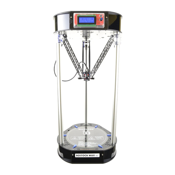
Step 2. REV2 Rostock Max v3 Base Assembly
Step 2. REV2 Rostock Max v3 Base Assembly
INTRODUCTION
This assembly guide will walk you though the steps of assembly the base of the Rostock Max v3
printer.
This document was generated on 2019-10-01 12:14:14 AM (MST).
© 2019
SeeMeCNC Guides
Second edition Rostock Max v3 assembly guide.
Written By: SeeMeCNC
seemecnc.dozuki.com/
Guide ID: 66 -
Draft: 2018-07-27
Page 1 of 12
Advertisement

Related Manuals for SeeMeCNC Rostock Max v3


Summary of Contents for SeeMeCNC Rostock Max v3
- Page 1 Second edition Rostock Max v3 assembly guide. Written By: SeeMeCNC INTRODUCTION This assembly guide will walk you though the steps of assembly the base of the Rostock Max v3 printer. This document was generated on 2019-10-01 12:14:14 AM (MST). © 2019 seemecnc.dozuki.com/...
- Page 2 Step 2. REV2 Rostock Max v3 Base Assembly Guide ID: 66 - Draft: 2018-07-27 Step 1 — Preparing for the Build The first step in preparing for your build is to remove the masking from both sides of all laser cut ...
- Page 3 Step 2. REV2 Rostock Max v3 Base Assembly Guide ID: 66 - Draft: 2018-07-27 Step 2 — Base Tower Supports Overview You'll be making three of these assemblies using injection molded parts 84407 & 84408 ( 1 each per assembly).
- Page 4 Then install the 1/4-20 button head screws and T-SLOT nuts. Remember to only get the nut started on the screw. Press the bearing / cover assembly (pre-assembled by SeeMeCNC) onto the posts inline with the 1/4-20 hardware (position shown) The two halves will be fastened together with #4 x 1/2"screws.
- Page 5 Step 2. REV2 Rostock Max v3 Base Assembly Guide ID: 66 - Draft: 2018-07-27 Step 4 — Installing Bed Insulator Clips Overview This animation will provide you with an overview of what will be assembled. This document was generated on 2019-10-01 12:14:14 AM (MST).
- Page 6 Step 2. REV2 Rostock Max v3 Base Assembly Guide ID: 66 - Draft: 2018-07-27 Step 5 — Installing Bed Insulator Clips Insert stainless steel nylon lock-nuts into the side with circular marks. Using 6-32 x 1" phillips pan head machine screws, gently tighten as shown. Blue bed clamps ...
- Page 7 Step 2. REV2 Rostock Max v3 Base Assembly Guide ID: 66 - Draft: 2018-07-27 Step 6 — Installing the PSU Blocker Overview This animation will provide you with an overview of what will be assembled. Step 7 — Installing the PSU Blocker Install the PSU Blocker sides using (2) M4 x 12 screws and washers per side (In base electronics ...
- Page 8 Step 2. REV2 Rostock Max v3 Base Assembly Guide ID: 66 - Draft: 2018-07-27 Step 8 — Foot & Leg Assembly Overview This animation will provide you with an overview of what will be assembled. Step 9 Make sure you don't over-tighten the nylon fasteners. They can be easily damaged if you over- ...
- Page 9 Step 2. REV2 Rostock Max v3 Base Assembly Guide ID: 66 - Draft: 2018-07-27 Step 10 — Assembly Power Input Panel Overview This animation will provide you with an overview of what will be assembled. Step 11 — Assembling the Power Input Panel When installing the power switch, ensure it's in the "off"...
- Page 10 Step 2. REV2 Rostock Max v3 Base Assembly Guide ID: 66 - Draft: 2018-07-27 Step 12 — Installing the Power Supply (PSU) Attach the PSU to the base plate using (2) 6-32 x 1" screws. Step 13 — Base Frame Assembly This animation will provide you with ...
- Page 11 Step 2. REV2 Rostock Max v3 Base Assembly Guide ID: 66 - Draft: 2018-07-27 Step 14 — Install AC Wiring Add connectors to the 200mm and 75mm wires as shown. The red & black wires for the cooling fan are connected to the first terminal in the V- and V+ ...
- Page 12 now complete. We will focus on the top assembly next. Step 16 — Wrap-Up This Sub-Assembly can be set aside until Step 4. Rostock Max v3 Final Assembly. Proceed to: Step 3. Rostock Max v3 Top Assembly ...
Need help?
Do you have a question about the Rostock Max v3 and is the answer not in the manual?
Questions and answers