
Related Manuals for SeeMeCNC Artemis 300


Summary of Contents for SeeMeCNC Artemis 300
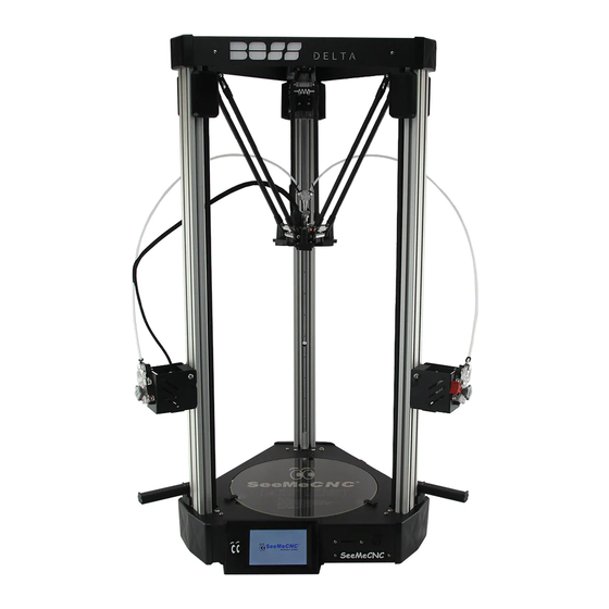
- Page 1 Assembling Artemis 300 SeeMeCNC Guides Assembling Artemis 300 This guide is your reference for the assembly of Artemis, the ultimate delta 3D printer. Written By: SeeMeCNC © 2018 seemecnc.dozuki.com/ Page 1 of 40...
- Page 2 INTRODUCTION Before you begin Please read this and all steps thoroughly before proceeding with your build. SeeMeCNC has gone through extensive research, testing, and manufacturing of the highest quality workmanship in this field. Close tolerances and fitment are necessary to ensure the accuracy customers expect. Be extra careful when handling edges such as on the tower assemblies.
- Page 3 Assembling Artemis 300 Step 1 — Read Me First First, click here to read safety information . This safety information may be updated at anytime so occasionally check for updates. NOTE: This guide is intended to be followed online in order to fully utilize the links and documentation found within.
- Page 4 Assembling Artemis 300 Step 2 — Unpacking Inside the large box that the Artemis 300 comes in, are the rails, and two medium sized boxes. Carefully remove the rails and set them aside. Remove the two medium sized boxes and CAREFULLY cut the packing tape.
- Page 5 Assembling Artemis 300 Step 3 — Accessory / Assembly Contents The smaller box in the base assembly pack is the accessory / assembly contents. Step 4 — Unpacking The other medium box is the upper assembly. You can carefully remove the shrink wrap from the upper assembly. NOTE: There is a small ...
- Page 6 Assembling Artemis 300 Step 5 — Artemis Contents Unpacked These are the parts that make up the Artemis 300. Step 6 — Z Tower There are 3 towers for the Artemis. 1 of the towers has the extruder and hot end whip pre-installed.
- Page 7 Assembling Artemis 300 Step 7 — Feeding the Wires in the Z Tower The first set of wires to feed in the Z Tower are the 18awg wires. These are the thicker wires from the Z Tower Wire Pack. Please ensure to have them oriented the correct way.
- Page 8 Assembling Artemis 300 Step 8 — KK Connectors THIS IS AN INFORMATIONAL STEP FOR FUTURE PROCEDURES. NO ACTION IS NEEDED FOR THIS STEP. Please watch the video. Make sure that the contact locks into the connector shell. The contact has a small metal tab.
- Page 9 Assembling Artemis 300 Step 10 — Installing Connectors on Wires There are two different connectors. The off-white connectors in the DUET controller box are slightly different than the KK Molex (bright white) connectors SeeMeCNC installs on the wires. If you need to...
- Page 10 Assembling Artemis 300 Step 11 — Installing Connectors on Stepper Motors Current machines will have the motor connectors already installed. Newest machines will have Red, Green, Yellow, and Blue wires instead of what is shown. If this is the case, ignore this step.
- Page 11 Assembling Artemis 300 Step 12 — X Tower Wires Please reference the wiring diagram in the image or click this link for the old version of wiring diagram if you have 2 orange wires: Whip Wiring. LED: Green Wire - 2 pin KK ...
- Page 12 Assembling Artemis 300 Step 13 — Preparing to Install Towers We will now begin to prepare the top of the machine to install the towers. There is a fan installed on the cover. Current machines have this connector already installed. If not, ...
- Page 13 Assembling Artemis 300 Step 15 — Duet Wifi Locations Overview This image is an overview of the Duet Wifi wire connection locations. You can reference it as needed. You can download it as a HERE © 2018 seemecnc.dozuki.com/...
- Page 14 Assembling Artemis 300 Step 16 — Installing the X Tower The X Tower will be the first tower to be installed. This tower is the one with the extruder and whip pre-installed. To begin, you will want to elevate the printer's upper assembly so it is up higher than the length of the rail.
- Page 15 Assembling Artemis 300 Step 17 — Installing the X Tower Continued You will now lift the tower and slowly slide it into the upper assembly. The tower assembly will clear the limit switch. As you are sliding it into place you will need to ensure that the wires stay down in their relief, otherwise they will get pinched when tightening the plate.
- Page 16 Assembling Artemis 300 Step 18 — Installing the Z Tower You will now install the Z tower, similarly to how you installed the X tower. The Z tower is the one in which you previously ran wires down. Start by making sure the end- stop legs are folded over.
- Page 17 Assembling Artemis 300 Step 19 — Install the Y Tower Install the final tower. This is the Y tower. It will install the same as the previous two towers, with the exception that this tower has no wires installed so you will not have to worry about pinching any wires.
- Page 18 Assembling Artemis 300 Step 20 — Wago Connector Information THIS IS AN INFORMATIONAL STEP FOR FUTURE PROCEDUREs. NO ACTION IS NEEDED FOR THIS STEP. There is a wire strip length gauge on the side of the Wago connector. When you use this ...
- Page 19 Assembling Artemis 300 Step 21 — Hotend Power Connections The red and black 18awg wires from the X tower DO NOT have connectors. These are for the E0 Heat. You will install these wires in the Wago Connectors that are attached to the top of the power ...
- Page 20 Assembling Artemis 300 Step 22 — Hotend Probe Connector The hotend probe connector (4-pin red, blue, black, brown wires, exiting the X tower wire bundle) is keyed and will only connect in one direction in the location indicated in the photo.
- Page 21 Assembling Artemis 300 Step 24 — More Hotend Connections The green, orange, and purple wires exiting the X tower bundle connect to the locations shown in the photos. © 2018 seemecnc.dozuki.com/ Page 21 of 40...
- Page 22 Assembling Artemis 300 Step 25 — Extruder Motor Connector The extruder motor connector (4-pin red, green, yellow, blue wires, exiting the X tower wire bundle) is keyed and will only connect in one direction in the "E0" location indicated in the photo.
- Page 23 Assembling Artemis 300 Step 26 — X Tower Motor Connector The X tower motor connector (black 4-pin red, green, yellow, blue wires) will install in the X stepper position on the board. Plug the connector in so that the smooth flat side of the black connector is facing the outer edge of the Duet.
- Page 24 Assembling Artemis 300 Step 28 — Bed Thermistor Connector The bed thermistor connector (2-pin with 2 white wires, exiting the Z tower wire bundle) is keyed and will only plug in one direction in the location shown in the photo.
- Page 25 Assembling Artemis 300 Step 30 — Ground and Neutral Connectors The ground (green) and neutral (white) wires go to their respective locations on the power supply. Unscrew the clamps and reinstall with the ring terminals in place as shown.
- Page 26 The picture doesn't show cardboard under the machine because we at SeeMeCNC like to live on the edge. A surface that won't scratch the machine is really recommended here. Step 33 — Removing Base Assembly Cover To remove the cover, lift it straight up on all three corners.
- Page 27 Assembling Artemis 300 Step 34 — Identification of Tower Locations This image of the Lower Assembly will assist you in identifying the X Y & Z tower locations for correct installation. This image shows the base assembly upside down, as it would appear when preparing for installation.
- Page 28 Assembling Artemis 300 Step 36 — Prepare the IEC Connector Open the fuse drawer on the IEC connector. Insert the two fuses that were provided into the location. as seen in the image. Close the drawer. Step 37 — IEC Connections Locate the black and green wires with crimped connectors exiting the Z tower shown.
- Page 29 Assembling Artemis 300 Step 38 — Installing the IEC Connector You will secure the IEC Connector to the sheet metal with M3 x 10mm screws and nylon lock nuts. These nuts are hard to get to. It is easiest to hold them with a pair of needle nose pliers, and even ...
- Page 30 Assembling Artemis 300 Step 40 — Bed Thermistor Wires Your final two white 26awg wires exiting the Z tower in the bottom assembly will connect to the white toggle connector as shown. Make sure the connection is solid in this white connector. If they slip out, you will have to remove the bottom cover later to troubleshoot thermistor issues! ©...
- Page 31 Assembling Artemis 300 Step 41 — Tame the Wires Add a wire clamp to the aluminum plate and secure the loose wires. Secure the wires / Wago connectors to the T-Slot with a zip tie. Step 42 — Base Finished ...
- Page 32 Assembling Artemis 300 Step 43 — Installing Ball Joints Flip the printer back over and put it on a work surface. Team lifting may be required, as the printer is heavy. Locate and install the metal ball joints. Each ball joint is installed onto the carriage with (2) 1/2"...
- Page 33 Assembling Artemis 300 Step 44 — Installing Arms on Carriages Before installing the arms, apply the provided lubricant to the ball joints. Use a q-tip, finger, or similar item to apply a small amount of lubricant to each aluminum ball joint on the carriage and on the hot end (6 total ball joints) Next install the arms to the ball joints.
- Page 34 Assembling Artemis 300 Step 45 — Installing Arms on Hot End Install the hot end in the orientation shown in the images. The easiest way to install the arms is to attach one arm to one of the ball joints, then insert the ...
- Page 35 Assembling Artemis 300 Step 46 — Hotend Connections Part 1 Pull back the cable boots to give access to the connectors at the end of the whip. Plug in the 10 pin SL connector to its home on the hotend.
-
Page 36: Step 48 - Installing The Bowden Tube
Assembling Artemis 300 Step 48 — Installing the Bowden Tube The Bowden Tube is the clear tube that delivers the filament from the extruder (EZR Struder) to the hot end (SE300). Bunch the mesh loom up approximately 100mm from the top of the extruder and insert the Bowden ... - Page 37 Assembling Artemis 300 Step 49 — Installing the PTC Clips Slide a PTC clip onto the Bowden tube as shown. Insert the Bowden Tube into the top of the hot end. Lift up on the black ring in the top of the hot end and slide the PTC clip into the groove between the ...
- Page 38 Assembling Artemis 300 Step 50 — Perform Initial Power Up and Function Test At this time we will wait to install the two covers. We will perform the initial power up and check functions before buttoning up. For the sake of continuity though, we have included the installation of the covers in this guide.
- Page 39 Assembling Artemis 300 Step 51 — Install the Base Cover You will now re-install the base cover. Before doing so, make sure all wires are secured and not going to interfere with its installation. If you find a loose wire, use a zip tie to secure it to a piece of T-Slot.
- Page 40 Assembling Artemis 300 Step 53 — Done! Follow this guide for setting up your Artemis. Enjoy your new printer! This document was last generated on 2018-08-13 08:08:15 AM. © 2018 seemecnc.dozuki.com/ Page 40 of 40...
Need help?
Do you have a question about the Artemis 300 and is the answer not in the manual?
Questions and answers