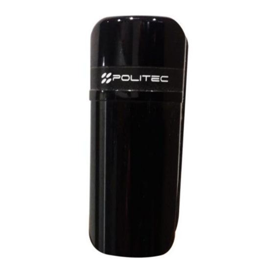
Summary of Contents for Politec ALES Series
- Page 1 PRODUCT ALES Product code ALES 60 ALES 120 ALES DOUBLE OPTIC PERIMETER BARRIER INSTALLATION AND MOUNTING MANUAL VERSION 2.1...
-
Page 2: Table Of Contents
13.Intervention time adjustment ……. ………. ……………………………… .. …………………………………...…. …… .17 14.Technical specifications ………………………. ……. …………………………………… .. ……………………………. …… 17 15.FAQ .............................18 16.Product disposal ……………………… .. ……………………………………. ……………………………………..……… .19 ALES 60 | 120 POLITEC | INSTALLATION MANUAL - VER.2.1... -
Page 3: Introduction
The system has been designed to detect intrusions and activate the alarm; it is not a device that prevents intrusion.Politec is not responsible for damage, injury or loss caused by accidents, theft, force majeure (including momentary lightning-induced overcurrent), abuse, improper or incorrect use, faulty installation or inadequate maintenance. -
Page 4: General Warnings
• Manufacturer's liability:Politec assumes no liability for failures resulting from incorrect installation; lack of maintenance, incorrect assembly or use. • Politec is also not liable for incorrect or incomplete operation of the product or failure to detect intrusion. •... -
Page 5: List Of Main Components
Cover opening tamper Horizontal adjustment lock screw Vertical adjustment screw High intensity alignment LEDs only on (RX) Alignment buzzer only on (RX) U-shaped bracket for pole fixing Wall fixing plate ALES 60 | 120 POLITEC | INSTALLATION MANUAL - VER.2.1... -
Page 6: Preparation For Installation
• Check that the surface chosen for the installation of the product is sturdy so as to ensure stable fixing and that it is adequately protected against possible impacts or the elements. ALES 60 | 120 POLITEC | INSTALLATION MANUAL - VER.2.1... -
Page 7: Examples Of Assembly/Fixing
WARNING: Product warranty is invalid if there is any hole in the aluminium profile or any component ALES 60 | 120 POLITEC | INSTALLATION MANUAL - VER.2.1... - Page 8 You must be careful not to alter the seals, plastics and mechanical parts of the product, and use the original accessories. In the case of repairs under warranty (2 years) but with evident signs of incorrect installation, Politec s.r.l. shall reserve the right to decide on any repair costs.
-
Page 9: Evaluations Before Installation
TX and RX, thus ensuring a good amount of signal constantly, even in case of particular climatic conditions. N.B.The ALES TS thermostat control kit is an optional accessory. ALES 60 | 120 POLITEC | INSTALLATION MANUAL - VER.2.1... -
Page 10: Barrier Positioning
DO NOT place barriers close to roads: vehicle lights directed towards the RX could create disturbances DO NOT place barriers near automatic gates: photocell signals can create interference ALES 60 | 120 POLITEC | INSTALLATION MANUAL - VER.2.1... -
Page 11: Wiring
ALES 60 | 120 POLITEC | INSTALLATION MANUAL - VER.2.1... -
Page 12: Connections To The Terminal Board
Fog disqualification (only on RX board) SMA test (only on RX board) 3 TRIMMER To adjust the intervention time (only on RX) 4 TMP Spring-loaded TAMPER to protect against cover removal ALES 60 | 120 POLITEC | INSTALLATION MANUAL - VER.2.1... -
Page 13: Barrier Alignment
It is sufficient to apply the filter only on the TX, there is no need to repeat the operation also on the RX. ALES 60 | 120 POLITEC | INSTALLATION MANUAL - VER.2.1... -
Page 14: Alignment Test
The maximum alignment condition will be reached when the high intensity LEDs are on steady and the buzzer will emit a continuous sound, for this reason, it may be necessary to make minor adjustments also on the RX optic. ALES 60 | 120 POLITEC | INSTALLATION MANUAL - VER.2.1... - Page 15 TRANSMITTER optic with your hand: if the RECEIVER continues to give a continuous beep, it means that it sees another infrared source that must be turned off and eliminated. ALES 60 | 120 POLITEC | INSTALLATION MANUAL - VER.2.1...
-
Page 16: Frequency Selection
1 2 3 4 1 2 3 4 1 2 3 4 1 2 3 4 1 2 3 4 1 2 3 4 1 2 3 4 1 2 3 4 ALES 60 | 120 POLITEC | INSTALLATION MANUAL - VER.2.1... -
Page 17: Intervention Time Adjustment
10/15Vdc = 6W, 0.8 A per pair 20/30Vdc = 6W, 0.4 A per pair Alarm and Tamper outputs NC Contacts Operating temperature -25° (with heating)+65° Ingress protection rating IP65 Pole/wall mounting accessories 2-YEAR FULL WARRANTY ALES 60 | 120 POLITEC | INSTALLATION MANUAL - VER.2.1... -
Page 18: Faq
TX and RX to double the attenuation of the beam; • For long distances it is recommended to use the additional external thermostat ensuring sufficient power, ALES 60 | 120 POLITEC | INSTALLATION MANUAL - VER.2.1... -
Page 19: Product Disposal
Warning!- Local regulations can impose heavy penalties for incorrect disposal of these products. ALES 60 | 120 POLITEC | INSTALLATION MANUAL - VER.2.1... - Page 20 For technical support, contact your security systems distributor...


Need help?
Do you have a question about the ALES Series and is the answer not in the manual?
Questions and answers