
Related Manuals for Politec MANA IR SMA


Summary of Contents for Politec MANA IR SMA
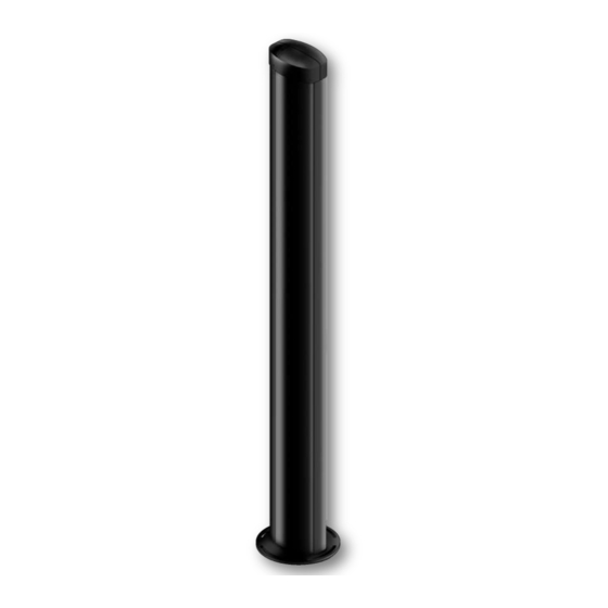
- Page 1 Infrared barrier for perimeter protection range 250 m SMA technology and RS485 output. Installation Manual.
- Page 2 Do not install multiple beams where the transmitter beam can interfere with other receiver beams. It is always better place either transmitter or receivers back to back. POLITEC s.r.l. | Manuale MANA IR SMA – Ver. 2.5...
- Page 3 Top cap Anti climbing cover (optional) Double Tamper Motherboard IR tube Optics receiver/transmitter 7 Ah battery support (optional) Aluminum profile Terminal block Supply card 12Vcc/24Vac Mana transformer 160 VA Aluminum base. POLITEC s.r.l. | Manuale MANA IR SMA – Ver. 2.5...
- Page 4 2. ASSEMBLING THE CABLEPIT Insert the highlighted edge into other section and fix with screws Insert the third section in the same way and fix with screws. POLITEC s.r.l. | Manuale MANA IR SMA – Ver. 2.5...
- Page 5 Enlarge the two opposite walls of cable pit to allow the positioning of last section. Insert and well fix the missing screws. POLITEC s.r.l. | Manuale MANA IR SMA – Ver. 2.5...
- Page 6 On the side that must be corrected loosen the insert in order to get the right inclination. Posizionamento corretto WRONG POSITIONING mediante regolazione inserti. Esempio di regolazione. POLITEC s.r.l. | Manuale MANA IR SMA – Ver. 2.5...
-
Page 7: Transformer Mounting
Move the screw 60mm, as shown in the figure, in the perforated plate and screw the bolt lock. Place the plate in the cavity, especially left, so you can screw tighten the screws to the column and have enough space for the battery. Screw the 4 screws POLITEC s.r.l. | Manuale MANA IR SMA – Ver. 2.5... - Page 8 Insert the sheath, the transformer then again the sheath and plate and fix everything with the nut. Follow the wiring instruction in the manual. POLITEC s.r.l. | Manuale MANA IR SMA – Ver. 2.5...
-
Page 9: Supply Connection
4. SUPPLY CONNECTION FUSE A: 5A-24Vac FUSE B: 0,8A-13,8Vac POLITEC s.r.l. | Manuale MANA IR SMA – Ver. 2.5... - Page 10 19 Vac Input to be connected to the transformer 13.8 Vdc Output for power infrared Power Connectors (terminal 8) 24 Vac Input to be connected to the transformer 24 Vac Output to be connected to the heaters POLITEC s.r.l. | Manuale MANA IR SMA – Ver. 2.5...
- Page 11 120Ω output if the voltage is supplied from> 12.4Vdc. Output high impedance if the voltage supplied from the transformer terminals "24Vin" is <18Vac. 120Ω output if the voltage supplied from the transformer terminals "24Vin" is> 18Vac. Not connected POLITEC s.r.l. | Manuale MANA IR SMA – Ver. 2.5...
-
Page 12: Cables And Wiring
The cable dimension depends on the columns consumption and on the same cable resistance, taking care about installation distances. Cable 12Vcc (sync + signal) Cable 230Vac (culomn power) POLITEC s.r.l. | Manuale MANA IR SMA – Ver. 2.5... - Page 13 (TX=>RX) output (TX=>RX) Negative sync input Negative sync - S IN 20 - S OUT (TX=>RX) output (TX=>RX) Not in use Not in use Not in use Not in use POLITEC s.r.l. | Manuale MANA IR SMA – Ver. 2.5...
- Page 14 The power of the heaters is by default set to 24 V (ac or dc), but you can set it to 12 VDC repositioning the jumper on MES9C and on each optical as shown. Heaters supply MES9C BOARD OPTICAL POLITEC s.r.l. | Manuale MANA IR SMA – Ver. 2.5...
- Page 15 2x0, 22, to connect the sync and the screens to negative Vdc of power supply on both columns. POLITEC s.r.l. | Manuale MANA IR SMA – Ver. 2.5...
- Page 16 (terminal numbers are related to the image of p. 11). Canal RX 1 2 3 4 Canal TX 1 2 3 4 DIP4 in OFF 1 2 3 4 5 6 7 8 9 10 11 12 POLITEC s.r.l. | Manuale MANA IR SMA – Ver. 2.5...
- Page 17 4; the selected channel must be the same on both TX and RX boards. Note: for information and for other configuration of MES9012, please check page 27. POLITEC s.r.l. | Manuale MANA IR SMA – Ver. 2.5...
- Page 18 COLUMN COLUMN COLUMN 2 COLUMN 1 Canal TX Canal TX 1 2 3 4 1 2 3 4 Canal RX Canal RX 1 2 3 4 1 2 3 4 POLITEC s.r.l. | Manuale MANA IR SMA – Ver. 2.5...
- Page 19 Each column can be connected via the RS485 bus to the control panel ADEBUS for planning, monitoring and managing local or remote system. For more information, refer to "Manual ADEBUS EXPLORER" 6.4.1. Connection to serial port for each column MES9C MES9C column 1 column 2 ADEBUS POLITEC s.r.l. | Manuale MANA IR SMA – Ver. 2.5...
- Page 20 The power of the heaters is set by default to 24V; you can use 12V by changing the configuration of the jumper (SW4). The voltage can be both AC and DC. Note: The settings and relative addresses are already set by Default. POLITEC s.r.l. | Manuale MANA IR SMA – Ver. 2.5...
- Page 21 The voltage can be both AC and DC. In jumper J4 is possible to read the signal value in volts. Note: The settings relating to addresses are already set to Default. POLITEC s.r.l. | Manuale MANA IR SMA – Ver. 2.5...
- Page 22 1 2 3 4 5 6 1 2 3 4 5 6 7 1 2 3 4 5 6 It should be set to ON the DIP on the motherboard RX exclusion 1 + 2 POLITEC s.r.l. | Manuale MANA IR SMA – Ver. 2.5...
- Page 23 Vertical adjustment Horizontal adjustment SCREW N.B.: FASTEN THE UNLOCKED SCREW AFTER THE ADJUSTMENT POLITEC s.r.l. | Manuale MANA IR SMA – Ver. 2.5...
- Page 24 3) Place the filter in front of the optic Transmitter you are aligning. It is recommended that the calibration with the use of the filter over long distances and then search for the maximum signal. POLITEC s.r.l. | Manuale MANA IR SMA – Ver. 2.5...
- Page 25 LEDs (with high brightness), the increase in the frequency of flashing (until the LEDs is fix on and the whistle of the corresponding BUZZER) indicate a better ALIGNMENT. With a FULL rotation on the horizontal RX lens, is carried out the SCANNING of the optical signal. POLITEC s.r.l. | Manuale MANA IR SMA – Ver. 2.5...
- Page 26 OFF THE LED NB: you can SEE the calibration value through the multimeter on each optical receiver. For this procedure, you must have the pair of lenses (TX-RX) in TEST. POLITEC s.r.l. | Manuale MANA IR SMA – Ver. 2.5...
- Page 27 4) Put in test the optical TX4 and RX4 and proceed with the calibration as explained N.B.: during the testing phase of an optical transmitter the other TX not in test are switched off automatically. POLITEC s.r.l. | Manuale MANA IR SMA – Ver. 2.5...
- Page 28 4) Put in test the optical TX4 and RX1 and proceed with the calibration as explained on p. 13 and 14. REPEAT the setting of RX2, RX3 and RX4. Make sure that it still aligned with RX1. POLITEC s.r.l. | Manuale MANA IR SMA – Ver. 2.5...
- Page 29 S.LOW Green HEATINGS LED Yellow SYNCHRONISM SYNC Yellow Response time TRIMMER adjustment TEST Function selector DIP SWITCH 12 (pag. 23) 10 TAMPER 11 DIP SWITCH TX 12 DIP SWITCH RX POLITEC s.r.l. | Manuale MANA IR SMA – Ver. 2.5...
- Page 30 Normally off, when turned on the heater is on. LED SINC The LED SINC continuously flashing indicates the proper Indicates the functioning of the operation and wiring of sync both outgoing and incoming. synchronism POLITEC s.r.l. | Manuale MANA IR SMA – Ver. 2.5...
- Page 31 In the ON position closes the RS485 communication. To finish you need to put in ON CLOSE RS485 only the switches of the column as far as the entire line. In the ON position activates the LEDs. LEDS POLITEC s.r.l. | Manuale MANA IR SMA – Ver. 2.5...
- Page 32 OFF Optical sync: operation with transmission frequency 4, only 2 receiver active JUMPER J7 If the disqualification function is activeted, you can increase the sensitivity of the disqualification by jumper J7 POLITEC s.r.l. | Manuale MANA IR SMA – Ver. 2.5...
- Page 33 (ex. animals). Adjusting the potentiometer clockwise decreases the trip time until 50ms. In this condition ensures the alarm of a person crossing the barrier running at maximum speed. POLITEC s.r.l. | Manuale MANA IR SMA – Ver. 2.5...
-
Page 34: Caratteristiche Tecniche
AND Random / AND 1° + 2° beam / exclusion 1° o 1° e 2° Specific for Infrared with HUV filter. PLASTIC SCREEN TOP CAP With Tamper. PROTECTION DEGREE IP 54 POLITEC s.r.l. | Manuale MANA IR SMA – Ver. 2.5... - Page 35 Check the correct sizing of the power cables; o If the system uses a switching power supply replace it with corresponding linear to avoid electrical interference from the network, it is recommended that the power supply LAR22. POLITEC s.r.l. | Manuale MANA IR SMA – Ver. 2.5...
- Page 36 For a more precise alignment position a side of the column cover in front of the lens in order to have two surfaces interposed between TX and RX for doubling attenuation of the beam. POLITEC s.r.l. | Manuale MANA IR SMA – Ver. 2.5...
- Page 37 POLITEC s.r.l. | Manuale MANA IR SMA – Ver. 2.5...
- Page 38 TECH DEPT: +39 039 9081616 POLITEC s.r.l. | Manuale MANA IR SMA – Ver. 2.5...
Need help?
Do you have a question about the MANA IR SMA and is the answer not in the manual?
Questions and answers