
Related Manuals for Honeywell HON 5020


Summary of Contents for Honeywell HON 5020
- Page 1 HON 5020 gas pressure regulator with HON 630 pilot User and maintenance manual Spare parts...
-
Page 2: Table Of Contents
Maintaining the control stage with a diaphragm assembly 8.5.3 Maintaining the control stage with a metal bellows assembly 8.5.4 Maintaining the control stage with a larger diaphragm assembly 8.5.5 Maintaining the load limiting stage HON 5020 gas pressure regulator with HON 630 pilot... - Page 3 Spare parts for load limiting stage 10.5 Spare parts for control stage 10.6 Spare parts for fine mesh filter 10.7 Spare parts for travel indication option 10.8 Lubricants, threadlockers, and special tools HON 5020 gas pressure regulator with HON 630 pilot...
-
Page 4: General Considerations
About this user manual Validity and purpose This user manual applies to HON 5020 gas pressure regulators featuring an HON 630 pilot. This user manual provides all individuals with the information required for the safe handling in connection with the following tasks: ... - Page 5 Constructive changes The written approval from Honeywell Gas Technologies GmbH, Kassel, is required for any modifications and additions to the product. Any violation will void the legal liability for con- sequences arising thereof.
- Page 6 CAUTION an accident may or will happen. minor or moderate bodily injury. Warnings about possible material damages are identified with the word Attention in this Warnings about material damages document. HON 5020 gas pressure regulator with HON 630 pilot...
-
Page 7: Description
Intended use Intended use HON 5020 gas pressure regulators featuring an HON 630 pilot can be used to maintain the outlet pressure of a gas constant within a regulating line regardless of the influence of dis- turbance variables such as inlet pressure changes and/or discharge changes. These devices are also characterized by high accuracy even in the event of large inlet pressure changes. -
Page 8: Device Models
Description Device models Gas pressure regulator Gas pressure regulators consisting of an HON 5020 regulator unit combined with an HON 630 versions pilot are available in a number of versions. These versions are derived from the various possible combinations between the various pilot and actuator assembly versions. -
Page 9: Labels/Markings
Body part number Batch number Foundry code CE PIN (only if the unit has been granted a CE type approval) Body nominal size Arrow indicating the direction of flow HON 5020 gas pressure regulator with HON 630 pilot... -
Page 10: Identifying The Device
Valve seat diameter Device version (IS = version with integral overpressure protection) Standard (EN 334) Manufacturing date (month/year) Connection Temperature range Failure function (fail-open) Maximum allowable pressure Maximum allowable inlet pressure HON 5020 gas pressure regulator with HON 630 pilot... - Page 11 The details on the type plate have the following meaning: plate of the pilot Figure Meaning Name of the device Serial number Maximum allowable pressure Controlled variable Specific set range Setpoint HON 5020 gas pressure regulator with HON 630 pilot...
-
Page 12: Layout And Operation
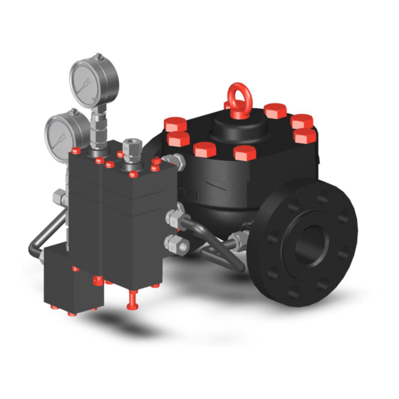
HON 630 pilot HON 5020 actuator assembly Gas pressure regulators consisting of an HON 5020 actuator assembly combined with How it works an HON 630 pilot can be used to maintain the outlet pressure of a gas constant within set limits within a regulating line regardless of the influence of disturbance variables such as inlet pressure changes and/or discharge changes. - Page 13 Description Load limiting stage (optional) Control stage Control stage spring adjuster Load limiting stage spring adjuster HON 905 fine mesh filter Inlet pressure gauge Amplifying valve Load limiting stage pressure gauge HON 5020 gas pressure regulator with HON 630 pilot...
- Page 14 Inside the load limiting stage, the double diaphragm system (much like the control stage) performs a setpoint/process value comparison between the loading pressure acting from above and the outlet pressure acting from below. HON 5020 gas pressure regulator with HON 630 pilot...
- Page 15 The positions open and closed are switched by means of a reed contact. The remote indication is also not a position indicator, but only shows whether or not the regulator is in operation. HON 5020 gas pressure regulator with HON 630 pilot...
-
Page 16: Technical Specifications
25 / 40 2″ (DN 50) 10.51 (267) 3.23 (82) 7.32 (186) 7.17 (182) 7.32 (186) 52.9 (24.0) 2″ (DN 50) 11.26 (286) 3.98 (101) 8.03 (204) 7.17 (182) 6.54 (166) 63.5 (28.8) HON 5020 gas pressure regulator with HON 630 pilot... - Page 17 (mm) inches (mm) inches (mm) inches (mm) inches (mm) lbs (kg) 1''-2" 16 / 31.5 (14.3) 25 / 33.7 (15.3) 33.7 (15.3) 1''-2" 31.1 (14.1) 1''-2" 33.7 (15.3) 1''-2" 36.6 (16.6) HON 5020 gas pressure regulator with HON 630 pilot...
- Page 18 246.5 (111.8) 4''-8" 253.4 (114.9) 4''-8" 228.0 (103.4) 4''-8" 256.7 (116.4) 4''-8" 310.0 (140.6) 6''-12'' 402.0 (182.3) 6''-12'' 454.0 (205.9) 6''-12'' 481.1 (218.2) 6''-12'' 423.6 (192.1) 6''-12'' 479.1 (217.3) 6''-12'' 703.0 (318.8) HON 5020 gas pressure regulator with HON 630 pilot...
- Page 19 The figure below shows the dimensions for the pilot with the control stages for setpoint ranges W = 0.5 – 90 bar: With outlet pressure gauge Without pressure gauge for outlet pressure 1 - 20 bar With outlet pressure gauge 10 - 90 bar HON 5020 gas pressure regulator with HON 630 pilot...
- Page 20 Maximum operating pressure Operating pressure, Criterion Value Class 600 1″ (DN 25), 2″ (DN 50), 3″ (DN 80), 4″ (DN 100), 6″ Nominal diameter (DN 150) 1480 psi (102 bar) Maximum operating pressure HON 5020 gas pressure regulator with HON 630 pilot...
- Page 21 Green (145 – 725 psi) 20 – 90 bar White (290 – 1305 psi) Load limiting stage 0.5 – 10 bar (7.3 – 145 psi) Green Automatically over outlet pressure p HON 5020 gas pressure regulator with HON 630 pilot...
- Page 22 The device’s mechanical components do not contain any potential sources of ignition, and accordingly do not fall under the scope of ATEX 95 (94/9/EC). The electrical components used on the device meet all applicable ATEX requirements. HON 5020 gas pressure regulator with HON 630 pilot...
-
Page 23: Safety
In particular, you have no permission to modify or disable any safety contrivanc- Adhere to the device maintenance intervals specified in this user manual. When replacing defective parts, only use original spare parts or manufacturer-approved standard parts. HON 5020 gas pressure regulator with HON 630 pilot... -
Page 24: Requirements Concerning The Workforce, Personal Protective Gear, Workplaces
Ability to identify and avoid dangers autonomously Knowledge with securing hauling distances Knowledge with the use of hoisting equipment Transportation Intra-company transport Professional training and experience personnel with the transport using stackers, etc. HON 5020 gas pressure regulator with HON 630 pilot... - Page 25 Tasked with the disposal Disposal of the device with the disposal of pressure equipment and systems Knowledge of the relevant standards and regulations Ability to identify and avoid dangers autonomously HON 5020 gas pressure regulator with HON 630 pilot...
- Page 26 The workplaces for performing the various tasks are at the following locations: Task Workplaces Installation All around the device, depending on the task Start-up Set-up Maintenance, repairs Decommissioning HON 5020 gas pressure regulator with HON 630 pilot...
-
Page 27: Basics For Installing The Device In A Pipe
- example 2 Indirect acting gas pressure regulator (pilot-operated) With expander without noise reduction element downstream of the gas pressure regu- lator Outlet pressure gauge with protection against overpressure HON 5020 gas pressure regulator with HON 630 pilot... - Page 28 Gas pressure regulator Pilot Safety relief valve Outlet stop valve armature Sensing point for connection lines (gray area) Feedback line Discharging line Gas pressure regulator measuring line Slam-shut device measuring line HON 5020 gas pressure regulator with HON 630 pilot...
-
Page 29: Alternative Application Example: Active Monitor Regulator
* Shut-off device with undisturbed flow pattern (ball valve) can be incorporated Alternative application example: Active monitor regulator Overview Active monitor regulator with HON 5020 monitor regulator unit (left) and HON 5020 active regulator unit (right): Schematic diagram: Measuring line (1), vent line (2) -
Page 30: Meter Run Characteristics
A gas pressure regulator with size the same outlet nominal size as The nominal size of the pipe is the inlet nominal size is used two standard nominal size min. 5 x DN increments larger HON 5020 gas pressure regulator with HON 630 pilot... -
Page 31: Operating And Measuring Lines
(e.g., diaphragm rupture), it can start conveying gas. Under certain operating conditions, and following consultation with the manufacturer, vent lines can be omitted if vent valves (HON 915) or safety diaphragm configurations can be used instead. HON 5020 gas pressure regulator with HON 630 pilot... - Page 32 On certain devices, the discharging line will be grouped with the feedback line. Feedback line When using indirect acting (pilot-operated) slam-shut devices, the feedback line is used to return the outlet pressure to the actuator. HON 5020 gas pressure regulator with HON 630 pilot...
-
Page 33: Transport And Installation
The transport route will be able to handle the load exerted by the total weight of the handling equipment and the load being transported. HON 5020 gas pressure regulator with HON 630 pilot... - Page 34 Install the ring bolts included in delivery and attach the slings to the ring bolts. Lift the HON 5020. Slowly and carefully transport the HON 5020 to the location where it will be installed. HON 5020 gas pressure regulator with HON 630 pilot...
-
Page 35: Installing The Gas Pressure Regulator
Install the flange gaskets. Screw down the flange crosswise in the specified order. When doing so, make sure to observe the torques specified by the flange gaskets’ manufacturer. HON 5020 gas pressure regulator with HON 630 pilot... -
Page 36: Installing The Device Connections
Basics for installing the device in a pipe (see page 27) section for more information on what needs to be ensured without fail in the corresponding design and implementation. HON 5020 gas pressure regulator with HON 630 pilot... -
Page 37: Checking The System For Leaks
Subjecting the device to pressure in the wrong direction may result in serious injury caused by bursting parts. Pressurize the system only on the inlet side. Details about the operating pressure can be found in the technical specifications. Technical specifications (see page 16) HON 5020 gas pressure regulator with HON 630 pilot... - Page 38 Proceed with step 4. Step Description Slowly close the inlet stop valve armature. Depressurize the inlet chamber and the outlet chamber. Seal the leaking pipe joints. Repeat the leak test starting with step 1. HON 5020 gas pressure regulator with HON 630 pilot...
-
Page 39: Adjusting The Settings Of The Device
Counterclockwise (-) to loosen the pilot spring Clockwise (+) to tighten the pilot spring Tighten the lock nut (1) to secure the set screw (2) setting. HON 5020 gas pressure regulator with HON 630 pilot... -
Page 40: Adjusting The Control Stage Setpoint
Turn the set screw: Clockwise (+) to tighten the pilot spring Counterclockwise (-) to loosen the pilot spring Open the outlet shut-off device. HON 5020 gas pressure regulator with HON 630 pilot... -
Page 41: Adjusting The Amplifying Valve
Carry out step 2a and then continue to step 3. response You want to slow down the actuator assembly’s Carry out step 2b and then continue to step 3. response, e.g., in the case that there are oscilla- tions HON 5020 gas pressure regulator with HON 630 pilot... - Page 42 As soon as you achieve the actuator assembly response you want, stop changing the spindle’s position. Put the amplifying valve cap back in place. HON 5020 gas pressure regulator with HON 630 pilot...
-
Page 43: Malfunctions
Check the actuator assembly’s high control diaphragm The screws and/or fittings were not Check the tightening torques tightened correctly Leaks on the outside The gaskets are faulty Check the gaskets for damage HON 5020 gas pressure regulator with HON 630 pilot... - Page 44 Unstable outlet pressure turer if necessary behavior (oscillations) Pilot not compatible with applica- Contact the manufacturer tion The amplifying valve setting is not Adjusting the amplifying valve (see correct page 41) HON 5020 gas pressure regulator with HON 630 pilot...
-
Page 45: Maintenance
(see page 50) Adjusting the loading pres- Adjusting the loading pressure (see sure page 39) Adjusting the control stage Adjusting the control stage setpoint setpoint (see page 40) HON 5020 gas pressure regulator with HON 630 pilot... -
Page 46: Preparing For The Maintenance
The maintenance instructions below are provided as examples for the various gas pressure instructions regulator models and versions. Use the bills of materials to make sure that you replace all the maintenance parts relevant to your specific device model during maintenance. HON 5020 gas pressure regulator with HON 630 pilot... -
Page 47: Starting Maintenance
Open the valve (5) in the blowdown line (6) to discharge the pressure between the inlet and the outlet valves. Purging the lines with All the gas pressure regulator’s lines must be purged with nitrogen before the device is re- nitrogen moved. HON 5020 gas pressure regulator with HON 630 pilot... - Page 48 The pilot needs to be removed from the actuator assembly. The actuator assembly, including the remaining pipes (with the exception of the motorization line), can remain in the gas regulating line. HON 5020 gas pressure regulator with HON 630 pilot...
- Page 49 Disconnect all the pilot pipes: Inlet pressure line (1) Motorization line (2) Measuring impulse line (3) Vent line (4) Outlet pressure line (5) Remove the pilot. HON 5020 gas pressure regulator with HON 630 pilot...
-
Page 50: Maintaining The Actuator Assembly
PN 16 Class 300 3/4″ UNC grade 7 6″ (DN 150) 353 Nm (260 ft lbs) PN 25/40 Class 600 1″ UNC grade 7 6″ (DN 150) 705 Nm (520 ft lbs) HON 5020 gas pressure regulator with HON 630 pilot... - Page 51 Check the noise reduction element and the support disc for damage and replace them if necessary. If the diaphragm is damaged: Dismantle the diaphragm unit. Replace the diaphragm with a new dia- phragm. HON 5020 gas pressure regulator with HON 630 pilot...
- Page 52 Next task Depending on what you want to do next, proceed as indicated in the relevant section: Maintaining the pilot (see page 53) Completing the maintenance (see page 88) HON 5020 gas pressure regulator with HON 630 pilot...
-
Page 53: Maintaining The Pilot
Proceed as follows: and maintaining the base Figure Step Description plate Unscrew the 4 screws (3) between the control stage (1) and the base plate (2) and remove the control stage. HON 5020 gas pressure regulator with HON 630 pilot... - Page 54 Turn the base plate over. Replace the 4 sealing rings (1) with new, greased ones. Lubricate the thread surfaces before screwing the fittings back in. Remove the cap from the amplifying valve. HON 5020 gas pressure regulator with HON 630 pilot...
- Page 55 Slide the spindle into the sleeve and screw in the spindle all the way to the position shown. The notch on the spindle should be flush with the sleeve’s front edge. HON 5020 gas pressure regulator with HON 630 pilot...
-
Page 56: Maintaining The Control Stage With A Diaphragm Assembly
Observe the tightening torques below when following the instructions in this section: Part Tightening torque Step Hex nut 12 Nm (9 ft lbs) Closing cap 20 Nm (15 ft lbs) Base plate screws 12 Nm (9 ft lbs) HON 5020 gas pressure regulator with HON 630 pilot... - Page 57 Unscrew the cap (1) while using an open-end wrench to hold the diaphragm plate (2) in place so as to prevent the components from turning. Replace the O-ring (3) in the cap with a new, greased O-ring. HON 5020 gas pressure regulator with HON 630 pilot...
- Page 58 Hold on to the connecting piece (1) and pull out the valve insert (2). Remove the connecting piece. Replace the valve insert with a new one. Insert a new, greased O-ring (1). HON 5020 gas pressure regulator with HON 630 pilot...
- Page 59 Align the valve body (1) as shown. Hold the connecting piece (2) in position. Insert the assembly aid, with the milled surface (3) facing upward towards the piston opening, into the valve body. HON 5020 gas pressure regulator with HON 630 pilot...
- Page 60 (1) and the nozzle opening is pointing upwards. Insert the valve insert (2) as far as it will go into the connecting piece (1). HON 5020 gas pressure regulator with HON 630 pilot...
- Page 61 Use the cap to turn the diaphragm by hand so that the marking on the diaphragm is right between the two markings on the body. Place the valve body on the spring housing. HON 5020 gas pressure regulator with HON 630 pilot...
- Page 62 (1) from the spring housing. Lubricate the spring plates’ depressions and reinsert the parts into the spring housing in the right order and alignment. Replace the base plate gasket with a new, greased one. HON 5020 gas pressure regulator with HON 630 pilot...
-
Page 63: Maintaining The Control Stage With A Metal Bellows Assembly
If necessary, secure removed components so that they will not fall or topple over. Wear the required personal protective equipment. Exercise caution when performing the relevant tasks. HON 5020 gas pressure regulator with HON 630 pilot... - Page 64 Loosen the screws and lift off the upper cover. Unscrew the fitting (1) on the upper cover. Replace the sealing ring (2) with a new, greased sealing ring. Lubricate the thread surfaces. Screw the fitting (1) back in. HON 5020 gas pressure regulator with HON 630 pilot...
- Page 65 (3) from the spring housing. Remove the compression spring (1) and the upper spring plate (2) from the spring housing. Unscrew the metal bellows’ internal screws (1) from the lower section of the spring housing. HON 5020 gas pressure regulator with HON 630 pilot...
- Page 66 (2) in place so as to prevent the components from turning. Replace the O-ring with a new, greased O-ring. Remove the pistons from the connecting piece. HON 5020 gas pressure regulator with HON 630 pilot...
- Page 67 Replace the valve insert with a new one. Insert a new, greased O-ring (1). Align the valve body as shown. Insert the assembly aid, with the milled surface facing upward towards the piston opening, into the valve body. HON 5020 gas pressure regulator with HON 630 pilot...
- Page 68 Turn the valve insert in such a way that, as shown in the sectional view, the dowel pin (3) is coaxially aligned with the lower hole (1) and the nozzle opening (2) is facing upward. HON 5020 gas pressure regulator with HON 630 pilot...
- Page 69 Use the cap to turn the diaphragm by hand so that the marking on the diaphragm is right between the two markings on the body. Replace the O-ring (1) with a new, greased O-ring. HON 5020 gas pressure regulator with HON 630 pilot...
- Page 70 (1). Reinsert the axial needle roller bearing (3), the axial washers (2), and the lower spring plate (1) into the spring housing from the bottom in the right order and alignment. HON 5020 gas pressure regulator with HON 630 pilot...
- Page 71 Unscrew the adjusting screw (2) and remove it from the base plate. Clean and lubricate the adjusting screw. Replace the hex flange nut (1) with a new one. Lubricate the thread surfaces. HON 5020 gas pressure regulator with HON 630 pilot...
-
Page 72: Maintaining The Control Stage With A Larger Diaphragm Assembly
20 Nm (15 lbs) Diaphragm housing screws 12 Nm (9 lbs) Hex nut 10 Nm (8 lbs) Diaphragm cover screws 12 Nm (9 lbs) Base plate screws 12 Nm (9 lbs) HON 5020 gas pressure regulator with HON 630 pilot... - Page 73 (1) and unscrewing the spring adjuster (2) a few turns. Unscrew the diaphragm cover’s screws (1). Unscrew the screw-in fitting. Remove the diaphragm cover. Remove the spring (1) from the hex nut. HON 5020 gas pressure regulator with HON 630 pilot...
- Page 74 (1). Unscrew the upper connecting piece (1) while using an open-end wrench to hold the diaphragm plate (2) in place so as to prevent the components from turning. HON 5020 gas pressure regulator with HON 630 pilot...
- Page 75 Hold on to the connecting piece (1) and pull out the valve insert (2). Remove the connecting piece. Replace the valve insert with a new one. Insert a new, greased O-ring (1). HON 5020 gas pressure regulator with HON 630 pilot...
- Page 76 Align the valve body (1) as shown. Hold the connecting piece (2) in position. Insert the assembly aid, with the milled surface (3) facing upward towards the piston opening, into the valve body. HON 5020 gas pressure regulator with HON 630 pilot...
- Page 77 Observe the tightening torque information provided in the table before this section. Remove the assembly aid (2) from the valve body. Screw the assembly aid (2) into the new valve insert (1). HON 5020 gas pressure regulator with HON 630 pilot...
- Page 78 Use the upper connecting piece to turn the diaphragm by hand so that the marking on the diaphragm is right between the two markings on the body. HON 5020 gas pressure regulator with HON 630 pilot...
- Page 79 Replace the diaphragm (2) with a new one. Put the diaphragm plate (3), the new diaphragm (2), and the pressure piece (1) back in place. HON 5020 gas pressure regulator with HON 630 pilot...
- Page 80 Put the spring (1) back in place. Take the diaphragm cover. Replace the O-ring (1) with a new, greased O-ring. Put the diaphragm cover back in place. Replace the O-ring (1) with a new, greased O-ring. HON 5020 gas pressure regulator with HON 630 pilot...
- Page 81 (1) from the spring housing. Lubricate the spring plates’ depressions and reinsert the parts into the spring housing in the right order and alignment. Replace the O-ring with a new, greased O-ring. HON 5020 gas pressure regulator with HON 630 pilot...
-
Page 82: Maintaining The Load Limiting Stage
If necessary, secure removed components so that they will not fall or topple over. Wear the required personal protective equipment. Exercise caution when performing the relevant tasks. HON 5020 gas pressure regulator with HON 630 pilot... - Page 83 Remove the base plate. Replace the O-ring (1) with a new, greased O-ring. Remove the cotter pin (1) from the cap nut. HON 5020 gas pressure regulator with HON 630 pilot...
- Page 84 Refer to the additional lubricant and tightening torque information at the beginning of this topic. Next task Proceed as follows: Maintaining the fine mesh filter (see page 85) HON 5020 gas pressure regulator with HON 630 pilot...
-
Page 85: Maintaining The Fine Mesh Filter
Remove the filter insert (1) and clean it. Check the filter cartridge for damage and replace it with a new one if necessary. Replace the O-ring (1) in the body with a new, greased O-ring. HON 5020 gas pressure regulator with HON 630 pilot... - Page 86 (1) with new, greased ones. Install the greased fittings back in place. Observe the tightening torque information provided in the table before this section. Next task Proceed as follows: Reassembling the pilot (see page 87) HON 5020 gas pressure regulator with HON 630 pilot...
-
Page 87: Reassembling The Pilot
Use the 4 hex bolts (3) and washers to fasten the control stage (1) back onto the base plate (2). Observe the tightening torque information provided in the table before this section. HON 5020 gas pressure regulator with HON 630 pilot... -
Page 88: Completing The Maintenance
Outlet pressure line (5) Result: The pilot is now installed on the actuator assembly and in the gas regulating line. Next task Proceed as follows: Checking the system for leaks (see page 37) HON 5020 gas pressure regulator with HON 630 pilot... -
Page 89: Storage, Removal, And Disposal
Before you start work- ing on these components: Close all connections leading to the gas-carrying line. Establish a depressurized status. Residual amounts of energy must be depressurized as well. HON 5020 gas pressure regulator with HON 630 pilot... - Page 90 When conducting work involving the pipework, please always observe the following: nections from being Figure Description twisted Do not twist the pipe connections in the assemblies. Use a second spanner wrench for securing when loosening and tightening pipe joints. HON 5020 gas pressure regulator with HON 630 pilot...
- Page 91 Recycle elements made of synthetic materials. Dispose of any other components according to the quality of the materials. HON 5020 gas pressure regulator with HON 630 pilot...
-
Page 92: Appendix
The required number of maintenance or servicing parts is indicated under the relevant part number in the “Part No.” column. If no quantity is specified, this means that only one unit is required. HON 5020 gas pressure regulator with HON 630 pilot... - Page 93 Control stage with larger diaphragm assembly Maintenance parts Servicing parts HON 905 fine mesh filter Maintenance parts Servicing parts Travel indication option Maintenance and servicing parts HON 5020 gas pressure regulator with HON 630 pilot...
-
Page 94: Spare Parts For The Hon 5020 Actuator Assembly
Appendix 10.2 Spare parts for the HON 5020 actuator assembly Spare parts drawing for actuator assembly Maintenance and servic- Nominal size No. / Name Part no. ing parts for actuator Letter assembly 1″ Diaphragm, up to 50 bar DP 201/MJ/001 1″... - Page 95 Diaphragm 50/70 bar DP 10011307 6″ O-ring 730ODVN261 6″ Closing spring 10011249 6″ Screws 710BCFE03010 6″ Flow restrictor, 100% 206/MZ/002 Flow restrictor, 75% 206/MZ/010 Flow restrictor, 50% 206/MZ/006 Flow restrictor 25% 206/MZ/011 HON 5020 gas pressure regulator with HON 630 pilot...
- Page 96 203/MJ/013 O-ring 730ODVN238 Nominal size No. / Name Part no. Letter 3″ 3" Class 600 5020 series IGP spare 203/MS-007 parts kit Diaphragm, up to 70 bar DP 203/MJ/014 O-ring 730ODVN238 HON 5020 gas pressure regulator with HON 630 pilot...
- Page 97 204/MJ/004 O-ring 730ODVN244 Nominal size No. / Name Part no. Letter 6″ 6" Class 150/300/600, PN 16/25/40 206/MS-001 series 5020 IGP spare parts kit Diaphragm 50/70 bar DP 10011307 O-ring 730ODVN261 HON 5020 gas pressure regulator with HON 630 pilot...
-
Page 98: Spare Parts For Two-Stage Hon 630 Pilot
Appendix 10.3 Spare parts for two-stage HON 630 pilot Spare parts drawing for pilot with larger diaphragm assembly HON 5020 gas pressure regulator with HON 630 pilot... - Page 99 Appendix Spare parts drawing for pilot with diaphragm assembly HON 5020 gas pressure regulator with HON 630 pilot...
- Page 100 Appendix Spare parts drawing for pilot with metal bellows assembly HON 5020 gas pressure regulator with HON 630 pilot...
- Page 101 For pressure rating PN 25/ANSI 150 100 418 100 418 For pressure rating PN 40 26 282 26 282 For pressure rating ANSI 300 26 283 26 283 26 285 HON 5020 gas pressure regulator with HON 630 pilot...
- Page 102 Name Part no. Larger diaphragm Diaphragm meas- Metal bellows assembly uring unit measuring unit Pressure gauge for the following specific setpoint ranges: W = 10-40 bar 26 282 26 282 HON 5020 gas pressure regulator with HON 630 pilot...
-
Page 103: Spare Parts For Load Limiting Stage
Spare parts drawing for The left half of the figure shows the standard design without an electric actuator. The right load limiting stage half shows the version with the electric actuator installed. HON 5020 gas pressure regulator with HON 630 pilot... - Page 104 (2 units) O-ring 20 293 Plate, pre-assembled 10 010 480 O-ring 20 226 Servicing parts for load Name Part no. limiting stage Spring collar 10 000 073 Compression spring 10 000 072 HON 5020 gas pressure regulator with HON 630 pilot...
-
Page 105: Spare Parts For Control Stage
Appendix 10.5 Spare parts for control stage Spare parts drawing for control stage with dia- phragm assembly HON 5020 gas pressure regulator with HON 630 pilot... - Page 106 10 000 066 (2 units) Hex flange nut 13 136 Servicing parts for control Name Part no. stage with diaphragm Spring collar See No. 22 assembly Compression spring See No. 23 HON 5020 gas pressure regulator with HON 630 pilot...
- Page 107 The left half of the figure shows the standard design without an electric actuator. The right control stage with metal half shows the version with the electric actuator installed. bellows assembly HON 5020 gas pressure regulator with HON 630 pilot...
- Page 108 10 010 444 For installation on electric actuator Spring plate for the following specific setpoint ranges: W = 10-50 bar 19 084 000 W = 20-90 bar 10 011 774 HON 5020 gas pressure regulator with HON 630 pilot...
- Page 109 Appendix Spare parts drawing for control stage with larger diaphragm assembly HON 5020 gas pressure regulator with HON 630 pilot...
- Page 110 Valve insert 10 000 061 O-ring 20 093 Servicing parts for control Name Part no. stage with larger dia- Spring collar 10 000 114 phragm assembly Compression spring 10 000 156 HON 5020 gas pressure regulator with HON 630 pilot...
-
Page 111: Spare Parts For Fine Mesh Filter
Spare parts drawing for HON 905 fine mesh filter Maintenance parts Name Part no. Gasket 18 842 (2 units) O-ring 20 317 O-ring 20 282 Servicing parts Name Part no. Filter insert 26 183 HON 5020 gas pressure regulator with HON 630 pilot... -
Page 112: Spare Parts For Travel Indication Option
10.7 Spare parts for travel indication option Spare part drawings Optical travel indicator Optical travel indicator with remote control Maintenance and servic- Name ing parts Part no. Part no. O-Ring 100448-RMK 20823 HON 5020 gas pressure regulator with HON 630 pilot... -
Page 113: Lubricants, Threadlockers, And Special Tools
Connecting piece threads Special tools You will need the following special tools for maintenance purposes: Application Special tools Part no. Maintaining the pilot (see page 53) Assembly aid 19 083 319 HON 5020 gas pressure regulator with HON 630 pilot... - Page 114 Honeywell's integrated gas solutions can help you to better manage your gas assets and optimize your value chain. Additional information To learn more about Honeywell’s product contact your Honeywell Process Solutions representative, or visit www.honeywellprocess.com or www.hongastec.de. Honeywell Process Solutions...
Need help?
Do you have a question about the HON 5020 and is the answer not in the manual?
Questions and answers