Advertisement
Quick Links
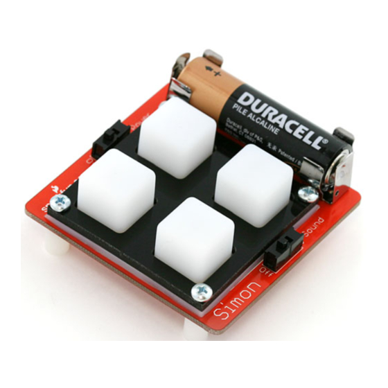
Simon SMD
Kit Information & Instructions
This is a kit of loose components that go along with the SMD Soldering Lecture. This is
considered an intermediate kit for people who have soldered through-hole components
before and wish to learn how to solder surface mount components. This kit comes with
a preprogrammed ATmega328. All parts are listed below.
Kit includes:
• NCP1402 IC
• 10k Ohm Resistor
• 47μF Capacitor
• 10μF Capacitor
• 0.1μF Capacitor (qty: 2)
• MBRA140 Diode
• 22μH Inductor
• 330 Ohm Resistors (qty: 4)
• Pre-programmed ATmega328 TQFP IC
Additional Tools Needed:
• Tweezers
• Soldering Iron
• Solder
• Buzzer
• LEDs (qty: 4)
• Battery Clips (qty: 2)
• Switches (qty: 2)
• Screws (qty: 4)
• Standoffs (qty: 4)
• Bezel Frame
• Button Pad
• Battery
• Solder Wick
• Flux
• Eye Protection
Page 1
Advertisement
Troubleshooting

Related Manuals for Sparkfun Electronics Simon SMD

Summary of Contents for Sparkfun Electronics Simon SMD
- Page 1 Simon SMD Kit Information & Instructions This is a kit of loose components that go along with the SMD Soldering Lecture. This is considered an intermediate kit for people who have soldered through-hole components before and wish to learn how to solder surface mount components. This kit comes with a preprogrammed ATmega328.
-
Page 2: Table Of Contents
TABLE OF CONTENTS SMD SOLDERING TIPS Section Page Parts List Soldering Tips SMD Soldering • Level 1 Don’t: Use the very tip of the iron. SMD Soldering • Level 2 Use the side of the tip of the iron, “The Sweet Spot.” PTH Soldering Final Assembly Touch the iron to the component leg and metal SMD pad at... - Page 3 Touch iron’s sweet spot to the start-pad for 2-3 seconds. QUICKSTART • LEVEL-1 SMD SOLDERING [ STEPS 1 T0 8 ] Steps highlighted in yellow represent a polarized component. Pay special attention to the component’s markings indicating how to place it on the board. Locate the Buzzer.
- Page 4 First, pull solder away. Solder should cover the entire pad and look like this - a tiny pillow. Second, remove the iron. Using your tweezers, position the buzzer slightly away from the pad. Page 6 Page 7...
- Page 5 For step 9, understand that alignment of the buzzer is very important. You want to ensure the buzzer is centered and laying flat against the board. See possible errors to the right (Page 9). Reheat Start-Pad Add solder to second pad. Slide Into Place GOOD Remove Iron...
- Page 6 BOTTOM OF BOARD CONTINUE WITH THE BOTTOM OF THE BOARD [ STEPS 10 T0 16 ] Now that you’ve successfully soldered down your first SMD component, use the same method to place and solder the following components. 10uF Capacitor The white end of the capacitor should point towards the rounded end on the PCB’s silkscreen.
- Page 7 BOTTOM OF BOARD 330 Resistors These resistors are not polarized. However, they do have a value marking on the top side. Make sure the marking is facing up. 330 Resistors 0.1uF Capacitors Ceramic capacitors like these are not polarized. They don’t have a value marking. This means they can be soldered into place in any rotation.
- Page 8 BOTTOM OF BOARD 47uF Capacitor The white line on the capacitor should point towards the rounded end on the PCB’s silkscreen. 47uF Capacitor 10K Resistor Just like the 330 resistors, these are not polarized. Make sure the writing on the part (‘103’) is facing up. 10K Resistor Remember, components highlighted yellow are polarized.
- Page 9 Touch iron’s sweet spot to the start-pad for 2-3 seconds. QUICKSTART • LEVEL-2 SMD SOLDERING [ STEPS 17 T0 21 ] Now that you’ve successfully soldered down all Level-1 components, you are ready to move on to Level-2. The next set of components have 5 or more pads each, and the pad size is smaller.
- Page 10 For step 21, use the same 3-step process you learned earlier (Step 8, Understand the alignment of the component is important, and should Page 8). A common error for these smaller types of components is a be oriented to look like the picture. jumper.
- Page 11 BOTTOM OF BOARD CONTINUE WITH THE BOTTOM OF THE BOARD Now that you’ve successfully soldered down your Level-2 SMD component, use the same method to place and solder the next component. You can choose any pad to be your Start-Pad. ATMega328 Microcontroller Match up the circle on the IC with that on the PCB’s silkscreen.
-
Page 12: Soldering Tips
QUICKSTART • PTH SOLDERING PTH SOLDERING TIPS Don’t: Use the very tip of the iron. Use the side of the tip of the iron, “The Sweet Spot.” Touch the iron to the component leg and metal ring at the same time. While continuing to hold the iron in contact with the leg and metal ring, feed solder into the joint. - Page 13 Insert the LED into the PCB, so that the short leg goes into the hole labeled with the “-” sign. CONTINUE WITH THE TOP OF THE BOARD [ STEPS 23 T0 27 ] Locate the LEDs (qty. 4). Push the LED in so it is flush with the board. Turn the board over and TOP OF BOARD locate one of the...
- Page 14 Pull the solder away. CONTINUE WITH THE BOTTOM OF THE BOARD [ STEPS 28 T0 31 ] For step 28 there are four sub-steps. Flip the board over. Hold the soldering iron’s “Sweet Spot” so it touches both the leg and the metal ring. Hold for 2 seconds. Remove the iron.
- Page 15 Your solder joint should look like this - a tiny volcano. Clip off any excess legs. Using the same PTH methods, add solder to the second leg. Page 28 Page 29...
- Page 16 TOP OF BOARD CONTINUE WITH THE TOP OF THE BOARD [ STEPS 32 T0 34 ] Now that you’ve successfully soldered your first PTH component, use the same method to place and solder the next components. LEDs (indicator lights) Just as you did with the first LED make sure the short leg goes into the hole labeled “-”.
- Page 17 TOP OF BOARD Slide Switches Keep the iron tip away from the black part of the switch! Plastic melts easily (and stinks). Slide Switches Battery Clips Both clips need to be pointed towards each other. The solid backing on each clip should face the outside of the board.
-
Page 18: Final Assembly
TOP SIDE VIEW FINAL ASSEMBLY [ STEPS 35 T0 38 ] No screwdriver necessary. Please only hand-tighten the screws and standoffs. Button Pad (game control) Attach to top. Lay rubber button pad over LEDs. Button Pad Bezel (holds button pad) Attach to top. Lay bezel over button pad, with notches for the screws pointing up. - Page 19 EXTRA FUN As an example of how the Simon is more than just a game, we have included a special feature in the code. Just for fun, try this out. Don’t worry it won’t change your Simon permanently. Turn off power switch. CONGRATULATIONS, YOU’RE DONE!!! Press any one button.
-
Page 20: Troubleshooting Leds
TROUBLESHOOTING LEDS TROUBLESHOOTING LEDS Using a hobby knife, cut both traces directly over the white dots. Failing LEDs? Don’t fret, there is an easy way to fix it! The most common cause of a failing LED is incorrect polarity. We have designed a special trick into the Simon PCB. -
Page 21: Troubleshooting Jumpers
Put a small amount of solder on the end of your iron (this will transfer TROUBLESHOOTING JUMPERS heat from iron to wick to the jumper). Sandwich the wick in between the iron and the solder jumper. As you solder the other pins down, if you solder multiple pins together, don’t worry about it! It can be easily fixed. -
Page 22: Notes
Notes Page 42 Page 43... -
Page 23: Learning More
© SparkFun Electronics, Inc. All Rights Reserved. The SparkFun Simon SMD Kit features, specifications, system requirements, and availability are subject to change without notice. All other trademarks contained herein are the property of their respective owners.
Need help?
Do you have a question about the Simon SMD and is the answer not in the manual?
Questions and answers