
Related Manuals for Hypertherm powermax1000


Summary of Contents for Hypertherm powermax1000
- Page 1 ® Plasma Arc Cutting System Operator Manual 804290 Revision 0 AMPS...
-
Page 2: Operator Manual
(P/N 804290) Revision 0 – September 2001 Hypertherm, Inc. Hanover, NH USA www.hypertherm.com © Copyright 2001 Hypertherm, Inc. All Rights Reserved Hypertherm and powermax are trademarks of Hypertherm, Inc. and may be registered in the United States and/or other countries. - Page 3 63457 Hanau-Wolfgang, Germany 49 6181 58 2100 Tel 49 6181 58 2134 Fax 49 6181 58 2123 (Technical Service) Hypertherm (S) Pte Ltd No. 19 Kaki Bukit Road 2 K.B. Warehouse Complex Singapore 417847, Republic of Singapore 65 6 841 2489 Tel...
- Page 4 The operator should be insulated from all ties are to be carried out. Hypertherm's CE-marked equipment is built such bonded metallic components. in compliance with standard EN50199. The The size of the surrounding area to be con-...
-
Page 5: Warranty
Hypertherm is notified of a defect (i) with respect to the punitive damages (including but not limited to lost power supply within a period of two (2) years from the date... -
Page 6: Table Of Contents
TABLE OF CONTENTS Electromagnetic Compatibility ........................i Warranty ...............................ii Section 1 Safety Recognize Safety Information ........................1-2 Follow Safety Instructions .........................1-2 Cutting Can Cause Fire or Explosion ......................1-2 Electric Shock Can Kill ..........................1-3 Cutting Can Produce Toxic Fumes......................1-3 A Plasma Arc Can Cause Injury and Burns....................1-4 Arc Rays Can Burn Eyes and Skin ......................1-4 Grounding Safety ............................1-4 Compressed Gas Equipment Safety ......................1-5... - Page 7 TABLE OF CONTENTS Torch Dimensions............................2-5 Symbols and Markings ..........................2-6 Section 3 Setup Upon Receipt ............................3-2 Claims ...............................3-2 Contents of Box............................3-2 Locating Power Supply ..........................3-2 Lifting Power Supply ..........................3-3 Power Connection .............................3-4 Three Phase Power Cord – Plug Installation ....................3-4 Single Phase Power Cord .........................3-5 Power Cord Installation ........................3-5 Plug Installation ..........................3-5 Grounding ..............................3-6...
- Page 8 TABLE OF CONTENTS Controls and Indicators ..........................5-4 Basic Troubleshooting ..........................5-5 System Circuit Diagram ..........................5-8 Technical Questions ..........................5-9 Parts ................................5-10 Torch Consumable Configurations ....................5-10 Torch Parts.............................5-11 Power Supply Parts ........................5-11 Accessories ...........................5-12 powermax 1000 Operator Manual...
- Page 9 TABLE OF CONTENTS powermax 1000 Operator Manual...
-
Page 10: Safety
Compressed Gas Equipment Safety ......................1-5 Gas Cylinders Can Explode If Damaged ....................1-5 Noise Can Damage Hearing ........................1-5 Pacemaker and Hearing Aid Operation.....................1-5 A Plasma Arc Can Damage Frozen Pipes ....................1-5 Additional Safety Information ........................1-5 Warning Label ............................1-6 Hypertherm Plasma Systems... -
Page 11: Recognize Safety Information
• Do not cut pressurized cylinders, pipes, or any table to eliminate the possibility of hydrogen closed container. detonation. Refer to the Appendix section of this • Do not cut containers that have held combustible manual for aeration manifold details. materials. Hypertherm Plasma Systems 11-98... -
Page 12: Electric Shock Can Kill
• Provide a disconnect switch close to the power • Each Hypertherm plasma system is designed to be supply with properly sized fuses. This switch allows used only with specific Hypertherm torches. Do not the operator to turn off the power supply quickly in substitute other torches which could overheat and an emergency situation. -
Page 13: A Plasma Arc Can Cause Injury And Burns
Work Table Connect the work table to an earth the power cord ground. Fasten the retaining nut ground, in accordance with appropriate national or tightly. local electrical codes. • Tighten all electrical connections to avoid excessive heating. Hypertherm Plasma Systems 5/6/02... -
Page 14: Compressed Gas Equipment Safety
Hazardous Substances, American Welding Society Protection Association, 470 Atlantic Avenue, Boston, MA 02210 550 LeJeune Road, P.O. Box 351040, Miami, FL 33135 10. OSHA, Safety and Health Standards, 29FR 1910 U.S. Government Printing Office, Washington, D.C. 20402 Hypertherm Plasma Systems 11-98... -
Page 15: Warning Label
Use welding helmet with correct shade of filter. Wear complete body protection. Become trained and read the instructions before working on the machine or cutting. 110212 Do not remove or paint over (cover) warning labels. Hypertherm Plasma Systems 8-01... -
Page 16: Section 1A
Les bouteilles de gaz comprimé peuvent exploser en cas de dommages ..........1a-5 Le bruit peut provoquer des problèmes auditifs ..................1a-5 Pacemakers et prothèses auditives ......................1a-5 Un arc plasma peut endommager les tuyaux gelés ................1a-5 Étiquette de sécurité ..........................1a-6 Hypertherm Systèmes plasma 1a-1 2/12/01... -
Page 17: Identifier Les Consignes De Sécurité
• Ne pas couper de bouteilles, de tuyaux ou autres Se référer à l’annexe du manuel pour plus de récipients fermés et pressurisés. renseignements sur les collecteurs d’aération. • Ne pas couper de récipients contenant des matières combustibles. 1a-2 Hypertherm Systèmes plasma 2/12/01... -
Page 18: Les Chocs Électriques Peuvent Être Fatals
• Chaque système plasma Hypertherm est conçu pour être • En cas d’utilisation d’une table à eau, s’assurer que cette utilisé uniquement avec des torches Hypertherm dernière est correctement mise à... -
Page 19: L'arc Plasma Peut Provoquer Des Blessures Ou Des Brûlures
Bien serrer l’écrou de retenue. Table de travail Raccorder la table de travail à la terre, • S’assurer que toutes les connexions sont bien serrées conformément aux codes de sécurité locaux ou nationaux pour éviter la surchauffe. appropriés. 1a-4 Hypertherm Systèmes plasma 5/6/02... -
Page 20: Sécurité Des Bouteilles De Gaz Comprimé
Les tuyaux gelés peuvent être endommagés ou éclater si • Se tenir le plus loin possible de la source de courant. l'on essaie de les dégeler avec une torche plasma. Hypertherm Systèmes plasma 1a-5 2/12/01... -
Page 21: Étiquette De Sécurité
Se former à la technique du coupage et lire les instructions avant de manipuler l’équipement ou de procéder au coupage. Ne pas retirer ou peindre (recouvrir) les étiquettes de sécurité. 1a-6 Hypertherm Systèmes plasma 2/12/01... -
Page 22: Specifications
Section 2 SPECIFICATIONS In this section: Specifications – Power Supply .........................2-2 Power Supply – Dimensions and Weight..................2-3 Specifications – T60 Torches ........................2-4 Torch Dimensions............................2-5 Symbols and Markings ..........................2-6 powermax 1000 Operator Manual... -
Page 23: Specifications - Power Supply
Drooping *Defined as a plot of output voltage versus output current Rated Output Current (I 20A – 60A Hypertherm Standard Rated Output 140 VDC Voltage (U Duty Cycle (X*) at 104°F (40°C) at – Volts AC rms rated conditions (U... -
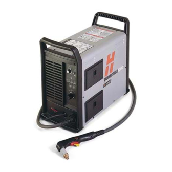
Page 24: Power Supply - Dimensions And Weight
SPECIFICATIONS Power Supply – Dimensions and Weight 10.5 in (267 mm) 23.1 in (586 mm) 76 lb (34.5 kg) 19.5 in AMP S (495 mm) Weight of power supply without torch powermax 1000 Operator Manual... -
Page 25: Specifications - T60 Torches
SPECIFICATIONS Specifications – T60 Torches Cutting Capacity At 60 Amps Recommended capacity 3/4 inch (19 mm) Maximum capacity 1 inch (25 mm) Severance capacity 1-1/4 inch (32 mm) Gouging Capability 10.0 pounds (4.5 kg) hour (metal removal rate on mild steel) Weight 6.9 pounds (3.1 kg) with 25 ft (7.5 m) lead 13.6 pounds (6.2 kg) with 50 ft (15 m) lead... -
Page 26: Torch Dimensions
SPECIFICATIONS Torch Dimensions T60 Hand Torch Dimensions 8.9" (226 mm) 1.5" (38 mm) 3.9" (99 mm) 2.25" (57 mm) 1.00" (25 mm) T60M/T80M Machine Torch Dimensions 15.06" (383 mm) 1.38" 1.00" (35 mm) (25 mm) 8" 1.13" (203 mm) (29mm) 32 pitch .125"... -
Page 27: Symbols And Markings
SPECIFICATIONS Symbols and Markings S MARK The S mark indicates that the power supply and torch are suitable for use in environments with increased hazard of electrical shock. The hand torches must have shielded consumable parts to maintain S mark compliance. IEC Symbols Used The following symbols may appear on the power supply data plate, control labels and switches. -
Page 28: Setup
Section 3 SETUP In this section: Upon Receipt ............................3-2 Claims ...............................3-2 Contents of Box............................3-2 Locating Power Supply ..........................3-2 Lifting Power Supply ..........................3-3 Power Connection .............................3-4 Three Phase Power Cord – Plug Installation ....................3-4 Single Phase Power Cord .........................3-5 Power Cord Installation ........................3-5 Plug Installation ..........................3-5 Grounding ..............................3-6 Extension Cords ............................3-6... -
Page 29: Upon Receipt
Quick Setup Card Locating Power Supply Locate the Powermax1000 power supply with at least 10 inches (0.25 m) of open space at the front and back and fan side of the power supply for proper ventilation. powermax 1000 Operator Manual... -
Page 30: Lifting Power Supply
SETUP Lifting Power Supply WARNING • The system weighs up to 83 lb / 38 kg. • Always lift the power supply by TWO handles • Do not lift the power supply by ONE handle. • The handle can break, resulting in injury and damage. Hoist Approved hoisting strap. -
Page 31: Power Connection
SETUP Power Connection The Powermax1000 is a universal power supply that can configure itself to operate with AC voltages from 200 to 600 (230-400 3PH for CE model). Use a line disconnect switch for each power supply so that the operator can turn off the power supply quickly in an emergency. -
Page 32: Single Phase Power Cord
SETUP Single Phase Power Cord (not for CE model) CAUTION: When using the standard model power supply (CE model is 3PH only) with a single-phase power source, replace the supplied power cord with a 8 AWG (10mm ) 3-wire power cord. The power cord must be connected by a licensed electrician. -
Page 33: Grounding
To ensure personal safety and proper operation, and to reduce electromagnetic interference (EMI), the Powermax1000 must be properly grounded through the power cord according to national or local electrical codes. Three-phase service must be of the 4-wire type with a green or green/yellow wire for protective earth ground and must comply with national or local electrical requirements. -
Page 34: Torch Installation
SETUP Torch Installation Turn OFF power. Remove power cord from power receptacle. Open ETR door and route lead through the end cap. Door End Cap powermax 1000 Operator Manual... - Page 35 SETUP Align marks on strain relief. Pull back Quick Release collar and insert the lead’s gas fitting. Quick Release Collar Slide Quick Release collar foward to lock in the gas fitting. Make sure that the gas fitting is secure. Make sure that the red dot on the connector is on top, then plug in the electrical connector. Close ETR door.
-
Page 36: Plasma Gas Supply
SETUP Plasma Gas Supply The gas supply for the Powermax1000 can be shop compressed air or cylinder compressed air. A high- pressure regulator must be used on either type of supply and must be capable of delivering gas to the filter on the power supply at 400 scfh/6.7 scfm (189 l/min), minimum flow rate, at a minimum pressure of... -
Page 37: Gas Supply Installation
SETUP Gas Supply Installation Connect the air hose as follows: 1. Air fitting • For standard model: Install 1/4 NPT gas fitting on to air filter inlet. CE model provides G1/4 adapter, in CE kit. Use liquid pipe sealant on threads. CAUTION: Never use Teflon tape when installing the nipple or adapters. -
Page 38: On/Off Pendant Connection
Inputs for arc start, with machine torch T60M, are available through the machine interface connection on the rear of the power supply. Plug the Hypertherm remote pendant (see Parts List for part numbers) into the connector on the rear panel. -
Page 39: Arc Voltage
SETUP WARNING ELECTRIC SHOCK CAN KILL Disconnect electrical power before performing any maintenance. All work requiring removal of the power supply cover must be performed by a qualified technician. Arc Voltage If arc voltage is necessary for activating a torch height control, the customer must supply an 18 AWG (1.0 mm ), single pair, unshielded cable rated for 300V or greater. - Page 40 SETUP 4. Find the power board. See figure below. Use insulated type 1/4" faston terminal ends to connect to J15 & J16. Note: 120VAC or 24 VAC must be sourced externally. Signal: Arc Voltage (torch height control) Type: Output Notes: Full arc voltage.
-
Page 41: Changing Xfer (Start Machine Motion) From Dry Contact Closure To Voltage Signal
SETUP Changing XFER (start machine motion) from dry contact closure to voltage signal 24 VDC (chassis ground reference) at 100ma max is available at J19 on Power PCB to drive a Isolated/Floating device such as a 24 VDC relay coil (240 ohms or greater) or a Typical Industrial Input Isolation Module (which has an opto-coupler built-in). - Page 42 SETUP Driving an Industrial Isolated Input Module START SIGNAL ISOLATED INPUT SHIELD MODULE – XFER ST ART Move Black wire and add Jumper as shown powermax 1000 Operator Manual 3-15...
- Page 43 SETUP powermax 1000 3-16 Operator Manual...
-
Page 44: Operation
Section 4 OPERATION In this section: Controls and Indicators ..........................4-2 Indicator LEDs ..........................4-2 Torch Consumable Configurations ......................4-3 Installing Torch Consumables ........................4-4 Mode Switch..............................4-5 Turn Power ON ............................4-5 Check Indicator Lights..........................4-5 Adjust Gas Pressure and Current Setting ....................4-6 Hand Torch Operation ..........................4-7 Safety Trigger Operation .........................4-7 Attach the Work Clamp........................4-8 Starting a Cut from the Edge of the Workpiece ................4-8... -
Page 45: Controls And Indicators
OPERATION Controls and Indicators ON (I) / OFF (0) Switch Current Mode Switch (Amps) AMPS Adjustment Knob Pressure Gauge Indicator LEDs Pressure Regulator Indicator LEDs Green Power ON LED When illuminated, indicates that power is applied to system and power switch is ON ( I ). Gas Pressure LED Yellow: When flashing, indicates that the gas pressure is below 60 psig (4.1 bar) for cutting,... -
Page 46: Torch Consumable Configurations
OPERATION Torch Consumable Configurations Hand-Held, Shielded O-Ring 058519 120929 120928 120932 120929 120928 120931 120926 120925 Gouging 120977 120928 220059 Unshielded* 120979 120928 220006 O-Ring 058519 120979 120928 220007 Mechanized, Shielded 120926 120925 120930 120928 120932 120930 120928 120931 * In CE countries, unshielded consumables may only be used in mechanized torch applications. -
Page 47: Installing Torch Consumables
OPERATION Installing Torch Consumables WARNING INSTANT-ON TORCHES PLASMA ARC CAN CAUSE INJURY AND BURNS Plasma arc comes on immediately when the torch switch is activated. The plasma arc will quickly burn through gloves and skin. Make sure power is OFF before changing consumables. Shield Retaining Cap Nozzle... -
Page 48: Mode Switch
OPERATION Mode Switch Use to cut expanded metal. Automatically reinitiates pilot. Use to cut plate/sheet metal. Optimum consumable life. Use to gouge, or for non-transfered-arc operation. Turn ON Power Position the power switch to ON (1) as shown. Check Indicator Lights Check that the POWER ON lamp is illuminated. -
Page 49: Adjust Gas Pressure And Current Setting
OPERATION Adjust Gas Pressure and Current Setting AMPS Set current knob to gas test. Push regulator knob to lock. AMPS Pull regulator knob to unlock. Turn current knob away from gas test to stop gas flow (20 amps minimum). Set pressure: Cutting 70–75 psig (4.8–5.2 bar) Gouging... -
Page 50: Hand Torch Operation
OPERATION Hand Torch Operation WARNING INSTANT-ON TORCHES PLASMA ARC CAN CAUSE INJURY AND BURNS Plasma arc comes on immediately when the torch switch is activated. The plasma arc will quickly burn through gloves and skin. • Keep away from the torch tip. •... -
Page 51: Attach The Work Clamp
OPERATION WARNING SPARKS AND HOT METAL CAN INJURE EYES AND BURN SKIN When firing the torch at an angle, sparks and hot metal will spray out from the nozzle. Point the torch away from yourself and others. Attach the Work Clamp Attach the work clamp securely to the workpiece. -
Page 52: Hand Torch Cutting Technique
• To cut thin material, reduce the amps until you get the best quality cut. • For straight-line cuts, use a straight edge as a guide. To cut circles, use a template or a Hypertherm circle cut guide, Part No. 027668. powermax... -
Page 53: Piercing
OPERATION Piercing WARNING SPARKS AND HOT METAL CAN INJURE EYES AND BURN SKIN When firing the torch at an angle, sparks and hot metal will spray out from the nozzle. Point the torch away from yourself and others. Hold the torch so that the nozzle is within 1/8 inch (3 mm) from the workpiece before firing the torch. Fire the torch at an angle to the workpiece, then slowly rotate it to an upright position. -
Page 54: Gouging
OPERATION Gouging WARNING SPARKS AND HOT METAL CAN INJURE EYES AND BURN SKIN When firing the torch at an angle, sparks and hot metal will spray out from the nozzle. Point the torch away from yourself and others. Hold the torch so that the nozzle is within 1/16 inch (1.5 mm) from the workpiece before firing the torch. Hold the torch at a 45 degree angle to the work piece. -
Page 55: Cut Charts
OPERATION Cut Charts 60 Amp Mechanized Shielded Consumables • Torch-to-work distance for the following cut chart is 1/16 inch (1.5 mm) for all cuts. Shield Retaining Cap Nozzle Electrode Swirl Ring T60M 120930 120928 120931 120926 120925 Torch Mild Steel Material Thickness Maximum Travel Speeds Optimum Travel Speeds... - Page 56 OPERATION 40 Amp Mechanized Shielded Consumables • Torch-to-work distance for the following cut chart is 1/16 inch (1.5 mm) for all cuts. Shield Retaining Cap Nozzle Electrode Swirl Ring T60M 120930 120928 120932 120926 120925 Torch Mild Steel Material Thickness Maximum Travel Speeds Optimum Travel Speeds Pierce...
- Page 57 OPERATION 40 Amp Unshielded Consumables • Torch-to-work distance for the following cut chart is 1/16 inch (1.5 mm) for all cuts. Deflector Retaining Cap Nozzle Electrode Swirl Ring T60M 120979 120928 220006 120926 120925 Torch Mild Steel Material Thickness Maximum Travel Speeds Optimum Travel Speeds Pierce Current...
-
Page 58: Maintenance And Parts
Section 5 MAINTENANCE AND PARTS In this section: Routine Maintenance ..........................5-2 Inspect Consumables..........................5-3 Controls and Indicators ..........................5-4 Basic Troubleshooting ..........................5-5 System Circuit Diagram ..........................5-8 Technical Questions ..........................5-9 Parts ................................5-10 Torch Consumable Configurations ....................5-10 Torch Parts.............................5-11 Power Supply Parts ........................5-11 Accessories ...........................5-12 powermax 1000 Operator Manual... -
Page 59: Routine Maintenance
MAINTENANCE AND PARTS Routine Maintenance WARNING ELECTRIC SHOCK CAN KILL Disconnect electrical power before performing any maintenance. All work requiring removal of the power supply cover must be performed by a qualified technician. Each Use Check consumables for wear Check gas pressure. and proper installation. -
Page 60: Inspect Consumables
Damage or debris Replace Central bore (I.D.) Does electrode slide easily? Replace Gas holes Blocked holes Replace Torch O-ring External surfaces Damage or wear Replace Dry surface Apply a thin film of Hypertherm grease (Part No. 027055) powermax 1000 Operator Manual... -
Page 61: Controls And Indicators
MAINTENANCE AND PARTS Controls and Indicators ON (I) / OFF (0) Switch Current Mode Switch (Amps) AMPS Adjustment Knob Pressure Gauge Indicator Pressure LEDs Regulator Indicator LEDs Green Power ON LED When illuminated, indicates that power is applied to system and power switch is ON ( I ). Gas Pressure LED Yellow: When flashing, indicates that the gas pressure is below 60 psig (4.1 bar) for cutting,... -
Page 62: Basic Troubleshooting
MAINTENANCE AND PARTS Basic Troubleshooting Problem Cause / Solution 1. The ON/OFF power switch is set to 1.1 The power cord is not plugged into the power I (ON), and the POWER ON (GREEN) receptacle. lamp is not illuminated. Plug the power cord into the receptacle. 1.2 The disconnect power switch is not set to ON or there is no power available to the disconnect power switch box. - Page 63 MAINTENANCE AND PARTS Basic Troubleshooting (continued) Problem Cause / Solution 5. The POWER ON (GREEN), TORCH 5.1 Retaining Cap is loose or removed from the PARTS LOOSE OR REMOVED torch. (YELLOW) and FAULT (RED) lamps are Turn off power supply and tighten or install torch illuminated.
- Page 64 MAINTENANCE AND PARTS Basic Troubleshooting (continued) Problem Cause / Solution 8. The arc sputters and hisses. 8.1 The gas filter element outside the power supply is contaminated. Replace filter element. 8.2 There is water in the air line. Clean air filter or add additional air filtration to power supply.
-
Page 65: System Circuit Diagram
MAINTENANCE AND PARTS System Circuit Diagram powermax 1000 Operator Manual... -
Page 66: Technical Questions
1. Call your Hypertherm distributor or authorized Hypertherm repair facility. 2. Call the nearest Hypertherm office listed in the front of this manual. 3. Request a Powermax1000 Service Manual for wiring diagrams, higher-level troubleshooting and more parts list information. -
Page 67: Parts
MAINTENANCE AND PARTS Parts Torch Consumable Configurations Hand-Held, Shielded O-Ring 058519 120929 120928 120932 120929 120928 120931 120926 120925 Gouging 120977 120928 220059 Unshielded* 120979 120928 220006 O-Ring 058519 120979 120928 220007 Mechanized, Shielded 120926 120925 120930 120928 120932 120930 120928 120931 * In CE countries, unshielded... -
Page 68: Torch Parts
MAINTENANCE AND PARTS Torch parts 083172 T60 Hand Torch Assembly, 25' 083171 T60 Hand Torch Assembly, 50' 083175 T60M Machine Torch Assembly, 15' 083174 T60M Machine Torch Assembly, 25' 083176 T60M Machine Torch Assembly, 35' 083177 T60M Machine Torch Assembly, 50' 027055 Silicon Lubricant, 1/4 Oz. -
Page 69: Accessories
MAINTENANCE AND PARTS Accessories 128646 Wheel Kit 128647 Optional Air Filtration Kit 011093 Replacement Filter For Optional Air Filtration Kit 011092 Replacement Filter Element For Filter Kit 027668 Circle Cutting Guide Assembly 027684 Replacement Bushing for Circle Cutting Guide Assembly 123646 50 Ft (15M) Work Cable w/ clamp 128711...
Need help?
Do you have a question about the powermax1000 and is the answer not in the manual?
Questions and answers