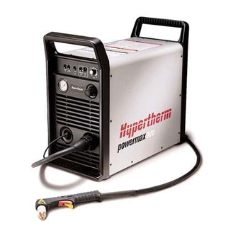
Hypertherm powermax900 Operator's Manual
Plasma arc cutting system
Hide thumbs
Also See for powermax900:
- Service manual (107 pages) ,
- Installation manual (21 pages) ,
- Field service bulletin (5 pages)
Table of Contents
Advertisement
Quick Links
Advertisement
Chapters
Table of Contents

Subscribe to Our Youtube Channel
Related Manuals for Hypertherm powermax900


Summary of Contents for Hypertherm powermax900
- Page 2 Revision 2 November, 2013 beginning with serial number 900-010000 Hypertherm, Inc. Hanover, NH USA http://www.hypertherm.com email:info@hypertherm.com © Copyright 2013 Hypertherm, Inc. All Rights Reserved HYPERTHERM and POWERMAX are trademarks of Hypertherm, Inc. and may be registered in the United States and/or other countries.
- Page 3 Hypertherm Offices Worldwide : Hypertherm, Inc. Etna Road, P.O. Box 5010 Hanover, NH 03755 USA Tel.: (603) 643-3441 (Main Office) Fax: (603) 643-5352 (All Departments) Tel.: (800) 643-9878 (Technical Service) Tel.: (800) 737-2978 (Customer Service) email: info@hypertherm.com (General Information) email: service@hypertherm.com (Technical/Customer Services)
-
Page 4: Electromagnetic Compatibility
Immunity of other equipment in the Equipotential Bonding environment. User shall ensure that Bonding of all metallic components in the Hypertherm's CE-marked equipment is other equipment being used in the cutting installation and adjacent to it built in compliance with standard environment is compatible. -
Page 5: Warranty
Hypertherm or operation of Equipment or any design, system, parts may not be covered by the Hypertherm formula, combination, article or material which warranty. -
Page 6: Table Of Contents
ABLE OF ONTENTS CONTENTS ELECTROMAGNETIC COMPATIBILITY ....................i WARRANTY ............................. ii SECTION 1 SAFETY ......................1-1 RECOGNIZE SAFETY INFORMATION ....................1-2 FOLLOW SAFETY INSTRUCTIONS ....................1-2 CUTTING CAN CAUSE FIRE OR EXPLOSION ................... 1-2 ELECTRIC SHOCK CAN KILL ......................1-2 CUTTING CAN PRODUCE TOXIC FUMES .................. - Page 7 ABLE OF ONTENTS VOLTAGE CONFIGURATIONS ......................3-4 POWER CORD PLUGS ........................3-6 POWER CORDS ........................... 3-6 208/240/480/600V Power Supplies ....................3-6 200/230/400V Power Supplies ......................3-6 SINGLE-PHASE AND THREE-PHASE POWER CONFIGURATIONS ..........3-7 Single-Phase ........................... 3-7 Three-Phase - Non-CE ........................3-7 Three-Phase - CE ...........................
- Page 8 PAC125M Torch Assembly and 35 ft (10.6 m) Lead - 083070 w/pigtail, 083074 no pigtail ... 5-11 PAC125M Torch Assembly and 50 ft (15.2 m) Lead - 083071 w/pigtail, 083075 no pigtail ... 5-11 Powermax900 Field Upgrade Kits and Optional Parts ..............5-12 POWER SUPPLIES - 208/240/480V, 1F/3F, 60 HZ ................5-12 POWER SUPPLIES - 200/230/400V, 1F/3F, 50/60 HZ ...............
- Page 9 ABLE OF ONTENTS ILLUSTRATIONS Figure 2-1 Powermax900 Hand Plasma Cutting System ............. 2-2 Figure 2-2 Powermax900 Power Supply with Dimensions ............2-3 Figure 2-3 PAC125T Torch with Dimensions ................2-4 Figure 2-4 PAC125M Torch with Dimensions................2-4 Figure 3-1 Powermax900 Power Supply Hoisting Setup ............. 3-3 Figure 3-2 Rear Panel ........................
- Page 10 Arc Rays Can Burn Eyes and Skin ................ 1-4 Grounding Safety ....................1-4 Compressed Gas Equipment Safety ..............1-5 Gas Cylinders Can Explode if Damaged ..............1-5 Noise Can Damage Hearing ..................1-5 Pacemaker and Hearing Aid Operation ..............1-5 Additional Safety Information ................. 1-5 Hypertherm Plasma Systems 8-99...
-
Page 11: Recognize Safety Information
Do not cut pressurized cylinders, pipes, or any table to eliminate the possibility of hydrogen deto- closed container. nation. Refer to the Appendix section of this manual • Do not cut containers that have held combustible for aeration manifold details. materials. Hypertherm Plasma Systems 8-99... -
Page 12: Electric Shock Can Kill
• Provide a disconnect switch close to the power grounding conductor first. supply with properly sized fuses. This switch allows • Each Hypertherm plasma system is designed to be the operator to turn off the power supply quickly in an used only with specific Hypertherm torches. Do not emergency situation. -
Page 13: Arc Rays Can Burn Eyes And Skin
Fasten the retaining nut tightly. Work Table Connect the work table to an earth • Tighten all electrical connections to avoid excessive ground, in accordance with appropriate national or local heating. electrical codes. Hypertherm Plasma Systems 8-99... -
Page 14: Compressed Gas Equipment Safety
Protection Association, 470 Atlantic Avenue, Boston, MA 02210 Hazardous Substances , American Welding Society 10. OSHA, Safety and Health Standards , 29FR 1910 550 LeJeune Road, P.O. Box 351040, Miami, FL 33135 U.S. Government Printing Office, Washington, D.C. 20402. Hypertherm Plasma Systems 8-99... - Page 15 AFETY Hypertherm Plasma Systems 8-99...
-
Page 16: Section 1A Sécurité
MISE À LA MASSE ET À LA TERRE ............... 1a-4 SÉCURITÉ DES BOUTEILLES DE GAZ COMPRIMÉ ........1a-5 LES BOUTEILLES DE GAZ COMPRIMÉ PEUVENT EXPLOSER EN CAS DE DOMMAGES ....................1a-5 LE BRUIT PEUT PROVOQUER DES PROBLÈMES AUDITIFS ..... 1a-5 PACEMAKERS ET PROTHÈSES AUDITIVES ..........1a-5 HYPERTHERM Systèmes plasma 1a-1 08/99... -
Page 17: Identifier Les Consignes De Sécurité
• Ne pas couper de récipients contenant des matières Se référer à l’annexe du manuel pour plus de combustibles. renseignements sur les collecteurs d’aération. 1a-2 HYPERTHERM Systèmes plasma 08/99... -
Page 18: Le Coupage Peut Produire Des Vapeurs Toxiques
• Installer un sectionneur avec fusibles appropriés, à la prise de terre appropriée. proximité de la source de courant. Ce dispositif permet à • Chaque système plasma Hypertherm est conçu pour être l’opérateur d’arrêter rapidement la source de courant en utilisé uniquement avec des torches Hypertherm cas d’urgence. -
Page 19: L'arc Plasma Peut Provoquer Des Blessures Ou Des Brûlures
Bien serrer l’écrou de retenue. Table de travail Raccorder la table de travail à la terre, • S’assurer que toutes les connexions sont bien serrées conformément aux codes de sécurité locaux ou nationaux pour éviter la surchauffe. appropriés. 1a-4 HYPERTHERM Systèmes plasma 08/99... -
Page 20: Sécurité Des Bouteilles De Gaz Comprimé
• Faire passer le faisceau de la torche le plus près possible du câble de retour. • Ne pas s’enrouler le faisceau de la torche ou le câble de retour autour du corps. • Se tenir le plus loin possible de la source de courant. HYPERTHERM Systèmes plasma 1a-5 08/99... - Page 21 ÉCURITÉ 1a-6 HYPERTHERM Systèmes plasma 08/99...
-
Page 22: Specifications
PECIFICATIONS Section 2 SPECIFICATIONS In this section: Introduction ...................... 2-2 Specifications ....................2-3 Power Supply ....................2-3 PAC125 Torches....................2-4 PAC125T Hand Torch Assembly..............2-4 PAC125M Machine Torch Assembly ............2-4 S Mark ......................2-5 IEC Symbols Used ................... 2-6 Operator Manual... -
Page 23: Introduction
The Powermax900 power supply provides constant-current output variable from 20 to 55 amps, for optimum performance on all thicknesses of metal up to 5/8" (16 mm) thick. At 55 amps, the Powermax900 can also cut metals up to 7/8" (22 mm) thick and will sever metals up to 1-1/8" (29 mm) thick. -
Page 24: Specifications
Width ..............10.4" (260 mm) without wheels 15.3" (390 mm) with wheels Height ..............19.6" (500 mm) without wheels 23.7" (620 mm) with wheels 27.7" (700 mm) for 600V power supply 10.4" 23.1" 19.6" Figure 2-2 Powermax900 Power Supply with Dimensions Operator Manual 10-98... -
Page 25: Pac125 Torches
PECIFICATIONS Weight ..............65 pounds (30 kg) without wheels 72 pounds (33 kg) with wheels 128 pounds (58 kg) for 600V and 230V-CE power supplies Gas Type .............. Air or Nitrogen Gas Quality, Air ............ Clean, dry, oil-free Gas Quality, Nitrogen ........... 99.995% pure Gas Inlet Pressure .......... -
Page 26: S Mark
PECIFICATIONS MARK The Powermax900 conforms to standard EN50192. The S mark indicates that the power supply and torch are suitable for use in environments with increased hazard of electrical shock. The hand torches must have shielded consumable parts to maintain S mark compliance. -
Page 27: Iec Symbols Used
PECIFICATIONS IEC SYMBOLS USED Direct Current (DC) Alternating current (AC) Plasma cutting torch AC input power connection The terminal for the external protective (earth) conductor An inverter-based power source Anode (+) work clamp Temperature switch Pressure switch Plasma torch in the TEST position (cooling and cutting gas exiting nozzle) Power is on Power is off Volt/amp curve, "drooping"... -
Page 28: Setup
ETUP Section 3 SETUP In this section: Upon Receipt ....................3-2 Claims ....................... 3-2 Hoisting Requirements ..................3-3 Voltage Configurations..................3-4 Power Cord Plugs ..................... 3-6 Power Cords ..................... 3-6 208/240/480/600V Power Supplies .............. 3-6 200/230/400V Power Supplies ..............3-6 Single-Phase and Three-Phase Power Configurations ........ -
Page 29: Upon Receipt
Claims for damage during shipment — If your unit was damaged during shipment, you must file a claim with the carrier. Hypertherm will furnish you with a copy of the bill of lading upon request. If you need additional assistance, call Customer Service listed in the front of this manual, or your authorized Hypertherm distributor. -
Page 30: Hoisting Requirements
If the power supply must be hoisted, read the Warning first and follow this procedure. See Fig. 3-1: WARNING The Powermax900 power supply weighs up to 135 pounds (61 kg). Do not hoist the power supply by one handle; it is not designed to support the weight of the power supply. -
Page 31: Voltage Configurations
Notes: • When switching to the 400 or 480V configuration, secure unused link box jumper in the clip located in the link box. • If using the 600V transformer option kit, configure the 3φ Powermax900 for 480V (Fig. 3-5). • See also Power Cords later in this section. -
Page 32: Figure 3-3 200V Or 208V Configuration
ETUP 200V or 208V Figure 3-3 200V or 208V Configuration Black White 230V or 240V Figure 3-4 230V or 240V Configuration Black White 400V or 480V Link Box Figure 3-5 400V or 480V Configuration Black White Operator Manual... -
Page 33: Power Cord Plugs
ETUP POWER CORD PLUGS All 208/240/480V power supplies are shipped with a single-phase power cord and plug. To operate as a three-phase unit, the user must obtain a power cord and plug that is certified by national or local electrical codes. The plug should be connected to the power cord by a licensed electrician. All 200/230/400V and 400V CE power supplies are shipped with a three-phase power cord and no plug. -
Page 34: Single-Phase And Three-Phase Power Configurations
ETUP SINGLE-PHASE AND THREE-PHASE POWER CONFIGURATIONS All Powermax900 power supplies except the 400V CE and 600V power supplies can operate from either a single-phase or three-phase input. The 400V CE, 230V CE and 600V power supplies operate only from a three-phase input. -
Page 35: Three-Phase - Ce
ETUP Three-Phase - CE Note: See also EMC Compatibility and Mains Supply on page i for further Conductor Color power (supply) cable Ground Green/Yellow shielding recommendations Brown L3 (W) Black (Filter Board) for CE compliance. L2 (V) Blue Blue L1 (U) Brown Black Green/... -
Page 36: Grounding Requirements
ETUP GROUNDING REQUIREMENTS To ensure personal safety, proper operation, and to reduce electromagnetic interference (EMI), the Powermax900 must be properly grounded: • The power supply must be properly grounded through the power cord according to your national or local electrical codes. The power supply chassis is electrically conductive and can present a shock hazard if it is not properly grounded through the line voltage disconnect box. -
Page 37: Gas Supply Requirements
ETUP GAS SUPPLY REQUIREMENTS The gas supply for the Powermax900 can be either air or nitrogen. Air can be supplied as shop compressed air or cylinder compressed air. Nitrogen can be supplied from compressed gas cylinders or liquid containers. A high-pressure regulator on either type of supply must be used and must be capable of delivering the following: 360 scfh/6 scfm (170 l/min) at a pressure of 90 psi (6.2 bar) to the filter on... -
Page 38: Gas Supply Connection
3. Turn the connector securing ring to the right to tighten. Note: The PAC121 torches (used with the Powermax800 and other Hypertherm products), cannot be connected to the Powermax900 power supply. -
Page 39: Pac125M On/Off Pendant Connection
1. Align the pendant lead connector key plug with the connector receptacle key slot on the pigtail and push in until pins seat. 2. Turn the connector securing ring to the right to tighten. Torch Lead Powermax900 On/Off Pendant power supply Machine Torch Pigtail... -
Page 40: Machine Interface With Pac125M
ETUP Torch 0° 90° Figure 3-14 Aligning the Machine Torch with Square MACHINE INTERFACE WITH PAC125M Signals for arc transfer and start are available on power supplies that have the machine interface option. The machine interface option is also available as an upgrade kit. WARNING Do not connect cutting machine interface START signal if using an ON/OFF pendant! •... -
Page 41: Arc Voltage
Figure 3-16 Feeding Arc Voltage Cable to Machine Interface Board (208/240/480V power supply shown) 4. Find the machine interface board on the top of the unit near the Powermax900 control board and connect the arc voltage cable as shown in Fig. 3-17. -
Page 42: Operation
PERATION Section 4 OPERATION In this section: Controls and Indicators ................... 4-2 Operating Instructions ..................4-3 Pilot Arc Controller Option ................4-4 PAC125T Safety Trigger Operation ............4-5 Operating Tips ....................4-6 Changing Consumable Parts..............4-6 Cutting ......................4-8 Piercing..................... 4-10 Gouging .....................4-11 Cut Chart - 50A Standard Consumables ............ -
Page 43: Controls And Indicators
Indicates gas pressure at power supply. • ON (I)/OFF (0) Power Switch Activates the power supply and its control circuits. ON (I)/OFF (0) Power Switch LINE TEST VOLTAGE TEMP PRESSURE POWER AMPS Pressure Gauge Pressure Regulator Figure 4-1 Powermax900 Controls and Indicators Operator Manual 9-99... -
Page 44: Operating Instructions
POWER ON AMPS PRESSURE GAUGE REGULATOR REGULATOR Figure 4-2 Powermax900 Operating Indicators and Adjustments 4. Adjust the gas pressure REGULATOR to read 70 psi (4.8 bar) on the PRESSURE GAUGE: • Pull the REGULATOR CAP out • Push the GAS TEST switch in •... -
Page 45: Pilot Arc Controller Option
Failure to do so can result in serious bodily injury. 7. The Powermax900 is now ready to operate. When you are ready to cut, place the tip of the torch at the edge of the workpiece. Pull the trigger to start the arc. See PAC125T Safety Trigger Operation later in this section for proper operation of the safety trigger. -
Page 46: Pac125T Safety Trigger Operation
PERATION PAC125T Safety Trigger Operation The PAC125T safety trigger torch allows operators to safely handle the torch before and after the cut and to minimize the possibility of accidental torch firing. The safety trigger is easy to operate. Follow the steps below. Safety On position. -
Page 47: Operating Tips
PERATION OPERATING TIPS Changing Consumable Parts WARNING SHOCK HAZARD: Always turn off power and unplug cord from wall before changing consumable parts. If power supply is directly connected to a line disconnect switch, place line disconnect switch in OFF position. Do not rely on the cap-on sensor switch to remove power. It is provided strictly for safety backup. -
Page 48: Figure 4-5 Consumables
PERATION Shields 120601 Nozzles Retaining Cap 120577 120600 Hand Shielded 120602 Machine Swirl Electrodes Ring PAC125 Gouging Shield 120600 120573 120576 Torch 120608 120607 Gouging O-Ring 044016 120578 Deflector 120574 120303 120600 Non-Shielded Extended 120606 Figure 4-5 Consumables Description of Consumables •... -
Page 49: Cutting
PERATION Cutting • Do not fire the pilot arc into the air needlessly—doing so causes a significant reduction of the nozzle and electrode life. • Start cutting from the edge of the workpiece (Fig. 4-6). • When cutting, make sure that the sparks are coming out of the bottom of the workpiece. If they are spraying on top of the workpiece, you are moving the torch too fast, or you do not have sufficient power to fully penetrate the workpiece. -
Page 50: Figure 4-7 Cutting A Circle
PERATION Figure 4-7 Cutting a Circle Figure 4-8 Dragging the Torch Operator Manual... -
Page 51: Piercing
PERATION Piercing • Hold the torch so that the nozzle is approximately 1/16 inch (1.6 mm) away from the workpiece before firing the torch. This method maximizes the life of the nozzle. • Hold the torch at an angle to the workpiece away from yourself, then slowly rotate it to an upright position. -
Page 52: Gouging
PERATION Gouging The Powermax900 can be used for gouging mild steel by using the optional gouging nozzle and gouging shield. To gouge: • Always wear full protection: - A welding helmet with at least a #8 lens shade - Welding gloves - A welding jacket The arc is fully exposed and will cause serious burns if the skin is not covered. -
Page 53: Cut Chart - 55A Standard Consumables
PERATION CUT CHART - 55A STANDARD CONSUMABLES The following recommended settings are for mechanized cutting at 55 amps. Torch-to-work distance for the following cut charts is 1/16 inch (1.6 mm) for all cuts. PAC125 Shield Retaining Cap Nozzle Electrode Swirl Ring Torch 120602 120600... -
Page 54: Cut Chart - 35A Consumables
PERATION CUT CHART - 35A CONSUMABLES Use 35 amp consumables on thin material to obtain maximum consumable life, a narrow kerf width and to minimize the heat-affected zone. The following recommended settings are for mechanized cutting. Torch-to-work distance is 1/16 inch (1.6 mm) for all cuts. Deflector Retaining Cap Electrode... -
Page 55: Common Cutting Faults
10-minute period, is affected by many factors. When the current is set at 55 amps, the Powermax900 has a 50% duty cycle at a temperature of 40° C (104° F). At these conditions, the plasma arc can remain on 5 minutes out of every 10 minutes without causing the tempera- ture sensors to disable the unit. -
Page 56: Maintenance/Parts
Consumable Configurations ............... 5-9 PAC125T Torch Assembly ................ 5-10 PAC125M Torch Assembly ................5-11 Powermax900 Field Upgrade Kits and Optional Parts ......5-12 Power Supplies - 208/240/480V ..............5-12 Power Supplies - 200/230/400V ..............5-12 Power Supplies - 400V CE ................5-13... -
Page 57: Introduction
Figure 5-1 Filter Assembly 3. Unscrew the filter bowl. 4. Unscrew the filter element. See Powermax900 Field Upgrade Kits and Optional Parts later in this section for part number information. 5. Clean the filter element with alcohol, then blow it out with air from the inside of the filter element. -
Page 58: Removal, Cleaning And Replacement Of The Cooling Air Filter
3. Remove the cover, and remove the cooling air filter from the clips by sliding the filter to the left and then up - Fig. 5-2. See Powermax900 Field Upgrade Kits and Optional Parts later in this section for part number information. -
Page 59: Basic Troubleshooting
LINE VOLTAGE LED is disabled (white) and See voltage configuration settings in the torch is disabled. Section 3. 3a.2 Line voltage is extremely low. The following table represents the operating range of the Powermax900 power supplies. Have an electrical technician check incoming power. Operator Manual 9-99... - Page 60 AINTENANCE ARTS Cause / Solution Problem Note: To avoid performance deterioration of the Powermax900, input voltage should be within 10% of the specified system line voltage setting. System Lower Limit Line Voltage Upper Limit 164VAC 200VAC 235VAC 170VAC 208VAC 239VAC...
- Page 61 AINTENANCE ARTS Cause / Solution Problem 3e. The LINE VOLTAGE LED is blinking red, 3e.1 There is an internal torch failure. and the power supply is disabled. Replace the torch. 4. The power supply shuts off after it turns on. 4.1 The torch is not connected to the power supply.
-
Page 62: Technical Questions
See Operating Tips in Section 4. TECHNICAL QUESTIONS If you are unable to fix the problem with your Powermax900 by following this basic troubleshooting guide or if you need further assistance: 1. Call your distributor or an authorized Hypertherm repair facility. -
Page 63: Parts
AINTENANCE ARTS PARTS Consumable Parts Kits Hand Consumable Parts Kit (128287) Part Number Description (Quantity) 001285 ....Box, Consumable Parts (1) 120573 ....Electrode (3) 120574 ....Electrode, Extended (1) 120577 ....Nozzle, 55A, Shielded (3) 120578 ....Nozzle, Pipe Saddle, Extended (1) 120607 .... -
Page 64: Consumable Configurations
AINTENANCE ARTS Consumable Configurations Shield Swirl Ring Retaining Cap Electrode PAC125 Nozzle 120601 120600 120576 120577 120573 Torch Shielded Hand Torch 55A Cutting Shield Swirl Ring Retaining Cap Nozzle Electrode PAC125 120602 120576 120600 120577 120573 Torch Shielded Machine Torch 55A Cutting Swirl Ring Shield... -
Page 65: Pac125T Torch Assembly And 25 Ft (7.6 M) Lead - 083066
AINTENANCE ARTS PAC125T Torch Assembly and 25 ft (7.6 m) Lead - 083066 PAC125T Torch Assembly and 50 ft (15.2 m) Lead - 083067 Part Number Description 001288 ......... Handle, PAC121/125T 002244 ......... Safety Trigger, PAC121/125T 128284 ......... Kit: Switch Repair 120573 ......... -
Page 66: Pac125M Torch Assembly And 14 Ft (4.3 M) Lead - 083069 W/Pigtail, 083073 No Pigtail
Torch Sleeve O-Ring 120613 044016 On/Off Pendant (not part of machine torch assembly - See Powermax900 Field Upgrade Kits and Optional Pigtail Parts later in this section for part numbers) Figure 5-6 PAC125M Torch Assembly and Leads 5-11 Operator Manual... -
Page 67: Powermax900 Field Upgrade Kits And Optional Parts
Part With Pilot Arc With Machine Number Torch Type Control Interface 083065 Hand 083082 Hand 083083 Machine 083084 Machine Note: Contact your distributor or call the nearest Hypertherm office for hand and machine torch system configurations. 5-12 Operator Manual 9-99... -
Page 68: Power Supplies - 400V Ce, 3F, 50 Hz
Part With Pilot Arc With Machine Number Torch Type Control Interface 083064 Hand 083079 Hand 083080 Machine 083081 Machine Note: Contact your distributor or call the nearest Hypertherm office for hand and machine torch system configurations. 5-13 Operator Manual 9-99... - Page 69 AINTENANCE ARTS 5-14 Operator Manual...
-
Page 70: Changing Fuses
In other countries, follow appropriate local or national safety procedures. 1. Turn the Powermax900 power switch to the OFF (0) position, unplug the power cable from the wall receptacle and disconnect the gas supply. See warning above. -
Page 71: Standards Index
PPENDIX TANDARDS NDEX STANDARDS INDEX The Standards Index contains a list of publications dealing with plasma arc cutting equipment safety practices. ANSI Standard Z49.1, Safety in Welding and Cutting , obtainable from the American Welding Society, 550 LeJeune Road, P.O. Box 351020, Miami, FL 33135. NIOSH, Safety and Health in Arc Welding and Gas Welding and Cutting , obtainable from the Superintendent of Documents, U.S. -
Page 72: Aeration Manifold
PPENDIX ERATION ANIFOLD PPENDIX AERATION MANIFOLD FOR PLASMA CUTTING ALUMINUM Introduction When plasma arc cutting aluminum at the water table surface or below water, free hydrogen gas may be generated by the cutting process. The high temperature of the plasma process causes disassociation of oxygen and hydrogen from the water in the water table. - Page 73 PPENDIX Operator Manual...
Need help?
Do you have a question about the powermax900 and is the answer not in the manual?
Questions and answers