Table of Contents
Advertisement
Quick Links
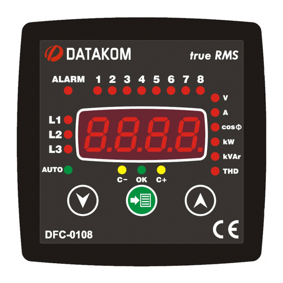
DFC-0108 POWER FACTOR CONTROLLER
8 BANKS, HARMONIC DISTORTION
DISPLAY
DFC-0108 is a high technology controller
allowing the power factor of the installation to
be stabilized to the requested value by
switching capacitor banks through contactors.
The unit allows also the visualization of
various AC parameters like a network
analyzer.
The unit makes harmonic analysis up to the
31th component. The THD values of all
voltages and currents are available.
Stepping algorithms are selectable between
various types. Thanks to the automatic setup
function, the commissioning and programming
are made easy.
SAFETY NOTICE
Failure to follow below
instructions will result in
death or serious injury
* Electrical equipment should be installed only
by qualified specialist. No responsibility is
assured by the manufacturer or any of its
subsidiaries for any consequences resulting
from the non-compliance to these instructions.
* Check the unit for cracks and damages due
to transportation. Do not install damaged
equipment.
* Do not open the unit. There is no
serviceable parts inside.
* Fuses of fast type (FF) with a maximum
rating of 6A must be connected to phase
voltage inputs, in close proximity of the unit.
* Disconnect all power before working on
equipment.
* When the unit is connected to the network
do not touch terminals.
* Short circuit terminals of unused current
transformers.
* Any electrical parameter applied to the
device must be in the range specified in the
user manual.
* Do not try to clean the device with solvent or
the like. Only clean with a dry cloth.
* Verify correct terminal connections before
applying power.
* Only for front panel mounting.
INSTALLATION
Before installation:
Read the user manual carefully, determine
the correct connection diagram.
Remove all connectors and mounting
brackets from the unit, then pass the unit
through the mounting opening.
Put mounting brackets and tighten. Do not
tighten too much, this can brake the
enclosure.
Make electrical connections with plugs
removed from sockets, then place plugs to
their sockets.
Be sure that relay outputs are not
overloaded. If necessary use extra
contactors.
Below conditions may damage the device:
Incorrect connections.
Incorrect power supply voltage.
Voltage at measuring terminals beyond
specified range.
Current at measuring terminals beyond
specified range.
Overload or short circuit at relay output
Current Transformers must be
used for current measurement.
No direct connection allowed
Below conditions may cause abnormal
Power supply voltage below minimum
acceptable level.
Power supply frequency out of specified
limits
Current transformers not matching related
phases.
Current transformer polarity incorrect.
Inadequate on-delay setting
Inadequate off-delay setting
Detailed user manual of this product
may be downloaded at:
www.datakom.com.tr
Advertisement
Table of Contents

Subscribe to Our Youtube Channel
Related Manuals for Datakom DFC-0108


Summary of Contents for Datakom DFC-0108
- Page 1 DFC-0108 POWER FACTOR CONTROLLER 8 BANKS, HARMONIC DISTORTION DISPLAY Before installation: DFC-0108 is a high technology controller Read the user manual carefully, determine allowing the power factor of the installation to be stabilized to the requested value by the correct connection diagram.
- Page 2 ELECTRICAL INSTALLATION REQUIRED PANEL DEPTH Do not install the unit close to high electromagnetic noise emitting devices like contactors, high current busbars, switchmode power supplies and the like. Although the unit is protected against electromagnetic disturbance, excessive disturbance can affect the operation and measurement precision.
- Page 3 PUSHBUTTON FUNCTIONS BUTTON FUNCTION In AUTO mode, acknowledges the displayed alarm. If the same alarm occurs again, it will not appear on the display. HELD PRESSED DURING 5 SEC: Resets all alarms and the alarm led. Any new coming alarm will appear on the display. HELD PRESSED DURING 10 SEC AT POWER-ON: The unit enters automatic setup mode.
- Page 4 TEST MODE, MANUAL STEP CONTROL Holding the pushbutton pressed for 5 seconds switches between TEST and MANUAL modes In TEST mode, if no button is pressed during 1 minute the unit will automatically return back to MANUAL mode. In TEST mode only the total kVAr value is displayed. When TEST mode is selected then the step-1 indicator led will flash.
- Page 5 AUTOMATIC SETUP In automatic setup mode, the unit :: -automatically detects and corrects reverse connected current transformers. -automatically measures and memorizes capacitor bank ratings. For a successful auto setup, voltage connections must be 3 phased. Otherwise the unit will give ALARM_01 and will not perform automatic setup.
- Page 6 STEP BY STEP AUTO SETUP PUSHBUTTON OPERATION DISPLAY In order to enter the auto setup mode, power- up the unit with MENU button pressed and hold the button pressed for 10 seconds. The display will show ctrF and the unit will ask the current transformer primary rating.
- Page 7 ALARMS The unit constantly monitors abnormal situations occurring in the system. Every monitored parameter has programmable alarm limits and delay timer. Alarms may be of latching or unlatching types. The automatic operation may be programmed to be aborted or continued. For more details please consider the PROGRAMMING section of this manual.
- Page 8 CONNECTION DIAGRAM GENERATOR PHASE...
Need help?
Do you have a question about the DFC-0108 and is the answer not in the manual?
Questions and answers