Table of Contents
Advertisement
Quick Links
D-500 User Manual Rev_06
DESCRIPTION
The D-500 is a next generation genset control unit
combining multi-functionality and wide
communication possibilities together with a reliable
and low cost design.
The unit complies and mostly exceeds world's
tightest safety, EMC, vibration and environmental
standards for the industrial category.
Software features are complete with easy firmware
upgrade process through USB port.
The Windows based PC software allows monitoring
and programming through USB, RS-485, Ethernet
and GPRS.
The PC based Rainbow Scada software allows
monitoring and control of an unlimited number of
gensets from a single central location.
FUNCTIONALITIES
AMF unit with uninterrupted transfer
ATS unit with uninterrupted transfer
Remote start controller
Manual start controller
Engine controller
Remote display & control unit
Waveform display of V & I
Harmonic analysis of V & I
CTs at genset or load side
Firmware V-5.8
D-500
ADVANCED
CONTROLLER
COMMUNICATIONS
Ethernet
GSM-GPRS
Internal GPRS modem (optional)
Embedded web server
Web monitoring
Web programming
GSM-SMS
e-mail
Modbus RS-485
Modbus TCP/IP
SNMP
USB Host (optional)
USB Device
RS-485
RS-232 (optional)
Micro SD card slot (optional)
J1939-CANBUS
TOPOLOGIES
2 phases 3 wires, L1-L2
2 phases 3 wires, L1-L3
3 phases 3 wires, 3 CTs
3 phases 3 wires, 2 CTs (L1-L2)
3 phases 3 wires, 2 CTs (L1-L3)
3 phases 4 wires, star
3 phases 4 wires, delta
1 phase 2 wires
GENSET
Advertisement
Table of Contents

Related Manuals for Datakom D-500


Summary of Contents for Datakom D-500
- Page 1 Firmware V-5.8 D-500 ADVANCED GENSET CONTROLLER DESCRIPTION COMMUNICATIONS The D-500 is a next generation genset control unit Ethernet combining multi-functionality and wide GSM-GPRS communication possibilities together with a reliable Internal GPRS modem (optional) and low cost design. Embedded web server Web monitoring The unit complies and mostly exceeds world’s...
- Page 2 D-500 family units. Follow carefully advices given in the document. These are often good practices for the installation of genset control units which reduce future issues. For all technical queries please contact Datakom at below e-mail address: datakom@datakom.com.tr QUERRIES...
- Page 3 D-500 User Manual Rev_06 Firmware V-5.8 REVISION HISTORY REVISION DATE AUTHOR DESCRIPTION 15.08.2012 Remote Monitoring and SNMP functionality added 01.10.2012 Revised for firmware version 3.2 01.10.2012 Revised for firmware version 3.3 18.04.2013 Revised for firmware version 3.9 19.06.2015 Revised for firmware version 5.4 06.05.2016...
- Page 4 D-500 User Manual Rev_06 Firmware V-5.8 ORDERING CODES The D-500 family units are available in various options and peripheral features. Please use below information for ordering the correct version: D500 -M -C -G -T -00 Variant 00: standard unit 01...99: customer...
- Page 5 D-500 User Manual Rev_06 Firmware V-5.8 SAFETY NOTICE Failure to follow below instructions will result in death or serious injury Electrical equipment should be installed only by qualified specialist. No responsibility is assured by the manufacturer or any of its subsidiaries for any consequences resulting from the non-compliance to these instructions.
-
Page 6: Table Of Contents
D-500 User Manual Rev_06 Firmware V-5.8 TABLE OF CONTENTS 1. INSTALLATION INSTRUCTIONS 2. MOUNTING 2.1 DIMENSIONS 2.2 SEALING, GASKET 2.3 ELECTRICAL INSTALLATION 3. TERMINAL DESCRIPTIONS 3.1. BATTERY VOLTAGE INPUT 3.2. AC VOLTAGE INPUTS 3.3. AC CURRENT INPUTS 3.4. DIGITAL INPUTS 3.5. - Page 7 D-500 User Manual Rev_06 Firmware V-5.8 5. FUNCTIONALITIES 5.1. CT LOCATION SELECTION 5.2. AMF FUNCTIONALITY 5.3. ATS FUNCTIONALITY 5.4. REMOTE START FUNCTIONALITY 5.5 ENGINE CONTROLLER FUNCTIONALITY 5.6. REMOTE DISPLAY UNIT FUNCTIONALITY 5.7. 400HZ OPERATION 6. CONNECTION DIAGRAMS 6.1. AMF FUNCTIONALITY, CTs AT LOAD SIDE 6.2.
- Page 8 D-500 User Manual Rev_06 Firmware V-5.8 14.5. WARNINGS 14.6. NON-VISUAL WARNINGS 15. PROGRAMMING 15.1. RESETTING TO FACTORY DEFAULTS 15.2. ENTERING THE PROGRAMMING MODE 15.3. NAVIGATING BETWEEN MENUS 15.4. MODIFYING PARAMETER VALUE 15.5. PROGRAMMING MODE EXIT 16. PROGRAM PARAMETER LIST 16.1. CONTROLLER CONFIGURATION GROUP 16.2.
- Page 9 D-500 User Manual Rev_06 Firmware V-5.8 30. LOAD TRANSFER MODES 30.1. TRANSFER WITH INTERRUPTION 30.2. UNINTERRUPTED TRANSFER 31. DATA RECORDING 31.1. DATA RECORDING MEDIA 31.2. DIRECTORY STRUCTURE 31.3. UNDERSTANDING THE CSV FORMAT 31.4. RECORDED DATA LIST, RECORD PERIOD 32. SOFTWARE FEATURES 32.1.
- Page 10 D-500 User Manual Rev_06 Firmware V-5.8 35. DECLARATION OF CONFORMITY 36. MAINTENANCE 37. DISPOSAL OF THE UNIT 38. ROHS COMPLIANCE 39. TROUBLESHOOTING GUIDE K35D05-EN - 10 -...
-
Page 11: Installation Instructions
D-500 User Manual Rev_06 Firmware V-5.8 1. INSTALLATION INSTRUCTIONS Before installation: Read the user manual carefully, determine the correct connection diagram. Remove all connectors and mounting brackets from the unit, then pass the unit through the mounting opening. -
Page 12: Mounting
D-500 User Manual Rev_06 Firmware V-5.8 2. MOUNTING 2.1. DIMENSIONS Dimensions: 200x148x47mm (7.9”x5.8”x1.9”) Panel Cutout: 176x121mm minimum (7.0”x4.8”) Weight: 450g (1 lb) K35D05-EN - 12 -... - Page 13 D-500 User Manual Rev_06 Firmware V-5.8 The unit is designed for panel mounting. The user should not be able to access parts of the unit other than the front panel. Mount the unit on a flat, vertical surface. Before mounting, remove the mounting brackets and connectors from the unit, then pass the unit through the mounting opening.
- Page 14 D-500 User Manual Rev_06 Firmware V-5.8 Two different types of brackets are provided: Self retaining type bracket Screw type bracket Installation of screw type bracket Installation of self retaining type bracket Do not tighten too much, this may break the unit.
-
Page 15: Sealing, Gasket
D-500 User Manual Rev_06 Firmware V-5.8 2.2. SEALING, GASKET Panel Gasket Module The rubber gasket provides a watertight means of mounting the module to the genset panel. Together with the gasket, 60529-IP65 protection can be reached from the front panel. A short definition of IP protection levels is given below. -
Page 16: Electrical Installation
D-500 User Manual Rev_06 Firmware V-5.8 2.3. ELECTRICAL INSTALLATION Do not install the unit close to high electromagnetic noise emitting devices like contactors, high current busbars, switchmode power supplies and the like. Although the unit is protected against electromagnetic disturbance, excessive disturbance can affect the operation, measurement precision and data communication quality. -
Page 17: Terminal Descriptions
D-500 User Manual Rev_06 Firmware V-5.8 3. TERMINAL DESCRIPTIONS 3.1. BATTERY VOLTAGE INPUT Supply voltage: 8 to 36VDC Cranking dropouts: Survives 0VDC during 100ms. The voltage before surge should be 8VDC minimum Overvoltage protection: Withstands 150VDC continuously. Reverse voltage: -33VDC continuous Maximum operating 500mA @ 12VDC. -
Page 18: Ac Voltage Inputs
D-500 User Manual Rev_06 Firmware V-5.8 3.2. AC VOLTAGE INPUTS Measurement method: True RMS Sampling rate: 8000 Hz Harmonic analysis: up to 31th harmonic Input voltage range: 14 to 300 VAC Minimum voltage for 15 VAC (Ph-N) frequency detection: Supported topologies:... -
Page 19: Ac Current Inputs
SELECTING THE CT ACCURACY CLASS: The CT accuracy class should be selected in accordance with the required measurement precision. The accuracy class of the Datakom controller is 0.5%. Thus 0.5% class CTs are advised for the best result. K35D05-EN - 19 -... - Page 20 D-500 User Manual Rev_06 Firmware V-5.8 Current Transformers must be used for current measurement. No direct connection allowed. No common terminals or grounding allowed. CONNECTING CTs: Be sure of connecting each CT to the related phase input with the correct polarity. Mixing CTs between phases will cause faulty power and pf readings.
- Page 21 D-500 User Manual Rev_06 Firmware V-5.8 EFFECT OF POLARITY REVERSAL The generator is still loaded with 100 kW On each phase. The load Power Factor (PF) is 1. PF in phase L2 will show -1,00 due to reverse CT polarity. The result is that total generator power displayed by the controller is 100 kW.
-
Page 22: Digital Inputs
D-500 User Manual Rev_06 Firmware V-5.8 3.4. DIGITAL INPUTS Number of inputs: 8 inputs, all configurable Function selection: from list Contact type: Normally open or normally closed (programmable) Switching: Battery negative or battery positive (programmable) Structure: 47 k-ohms resistor to battery positive, 110k-ohms to battery negative. -
Page 23: Charge Input Terminal
D-500 User Manual Rev_06 Firmware V-5.8 3.6. CHARGE INPUT TERMINAL The Charge terminal is both an input and output. When the engine is ready to run, this terminal supplies the excitation current to the charge alternator. The excitation circuit is equivalent to a 2W lamp. -
Page 24: Mains Contactor Output
D-500 User Manual Rev_06 Firmware V-5.8 3.8. MAINS CONTACTOR OUTPUT Structure: Relay output, normally closed contact. One terminal is internally connected to mains phase L1 input. Max switching current: 12A @250VAC Max switching voltage: 440VAC Max switching power: 3000VA 3.9. GENERATOR CONTACTOR OUTPUT Structure: Relay output, normally open contact. -
Page 25: Input/Output Extension
D-500 User Manual Rev_06 Firmware V-5.8 3.11. INPUT/OUTPUT EXTENSION The module provides resources for 32 additional digital inputs and 32 additional digital outputs. Digital inputs can be extended using DKG-188 I/O Extension Digital Input Extension modules, each one Connector providing 8 inputs. Digital inputs are programmable through the main controller. -
Page 26: Port
The RS-485 port features MODBUS-RTU protocol. Multiple modules (up to 128) can be paralleled on the same RS-485 bus for data transfer to automation or building management systems. The Modbus register list is available at Datakom technical support. The RS-485 port provides also a good solution for distant PC connection where RainbowPlus program will enable programming, control and monitoring. -
Page 27: Ethernet Port
D-500 User Manual Rev_06 Firmware V-5.8 3.14. ETHERNET PORT Description: IEEE802.3 compliant, 10/100 Base-TX RJ45 ethernet port with indicating leds Data rate: 10/100 Mbits/s, auto detecting Ethernet Connector: RJ45 Connector Cable type: CAT5 or CAT6 Isolation: 1500 VAC, 1 minute... -
Page 28: Usb Device Port
The RainbowPlus software can be downloaded from www.datakom.com.tr website. The connector on the module is of USB-B type. Thus A to B type USB cable should be used. This is the same cable used for USB printers. -
Page 29: Usb Host Port (Optional)
D-500 User Manual Rev_06 Firmware V-5.8 3.16. USB HOST PORT (OPTIONAL) USB HOST Port USB FLASH MEMORY The USB-Host port is available in units with COMM option. Description: USB 2.0, not isolated Power Supply 5V, 300mA max Output: Data rate: Full Speed 1.5/12 Mbits/s, auto detecting... -
Page 30: Port (Optional)
D-500 User Manual Rev_06 Firmware V-5.8 3.17. RS-232 PORT (OPTIONAL) Description: RS-232, non isolated. Functionality: External GSM modem, external PSTN modem Connector: DB-9 (9 pins male) Connection: 5 wires (Rx-Tx-DTR-CxD-GND). Full duplex. Baud rate: 2400-115200 bauds, selectable Data type: 8 bit data, no parity, 1 bit stop... -
Page 31: Micro-Sd Memory Card Slot (Optional)
D-500 User Manual Rev_06 Firmware V-5.8 3.18. MICRO-SD MEMORY CARD SLOT (OPTIONAL) USB HOST Port MICRO-SD Card Slot MICRO-SD MEMORY CARD The micro-SD card slot is available in units with COMM option. The slot is of push-in push-out type. When pushed in, the card is firmly held by its connector. -
Page 32: Gsm Modem (Optional)
D-500 User Manual Rev_06 Firmware V-5.8 3.19. GSM MODEM (OPTIONAL) The optional internal GSM modem offers the advantage of being internally powered and is fully compatible with the unit. It does not require any special setup. The 1800/1900 MHz magnetic antenna together with its 2 meter cable is supplied with the internal modem option. - Page 33 D-500 User Manual Rev_06 Firmware V-5.8 SIM CARD SIM CARD SIM CARD EXTRACTION EXTRACTION/INSERTION PLACEMENT Description: Quad-band GSM/GPRS 850/900/1800/1900MHz module. GPRS multi-slot class 12/12 GPRS mobile station class B Compliant to GSM phase 2/2+. – Class 4 (2 W @850/ 900 MHz) –...
-
Page 34: Topologies
D-500 User Manual Rev_06 Firmware V-5.8 4. TOPOLOGIES Various topologies are selectable through program parameter. The topology is independently selectable for both genset and mains sections. In following drawings the connections are shown for the alternator. Current transformers are supposed connected to the alternator side. -
Page 35: Phase, 4 Wire, Star
D-500 User Manual Rev_06 Firmware V-5.8 4.2. 3 PHASE, 4 WIRE, STAR 4.3. 3 PHASE, 3 WIRE, DELTA K35D05-EN - 35 -... -
Page 36: Phase, 4 Wire, Delta
D-500 User Manual Rev_06 Firmware V-5.8 4.4. 3 PHASE, 4 WIRE, DELTA 4.5. 3 PHASE, 3 WIRE, DELTA, 2 CT (L1-L2) K35D05-EN - 36 -... -
Page 37: Phase, 3 Wire, Delta, 2 Ct (L1-L3)
D-500 User Manual Rev_06 Firmware V-5.8 4.6. 3 PHASE, 3 WIRE, DELTA, 2 CT (L1-L3) 4.7. 2 PHASE, 3 WIRE, DELTA, 2 CTs (L1-L2) K35D05-EN - 37 -... -
Page 38: Phase, 3 Wire, Delta, 2 Cts (L1-L3)
D-500 User Manual Rev_06 Firmware V-5.8 4.8. 2 PHASE, 3 WIRE, DELTA, 2 CTs (L1-L3) 4.9. 1 PHASE, 2 WIRE K35D05-EN - 38 -... -
Page 39: Functionalities
D-500 User Manual Rev_06 Firmware V-5.8 5. FUNCTIONALITIES The same unit provides different functionalities through parameter setting. Thus a single stock item will fulfill various duties, minimizing stock cost. 5.1. CT LOCATION SELECTION CTs may be placed at alternator or load busbars. The CT location selection is configured with Controller Configuration >... -
Page 40: Engine Controller Functionality
D-500 User Manual Rev_06 Firmware V-5.8 5.5 ENGINE CONTROLLER FUNCTIONALITY When the Engine Controller functionality is selected, genset electrical measurements and protections will be disabled. The unit is supposed to control an engine without alternator. When the Engine Control Mode is activated: -the unit will not display genset AC parameters (volts, amps, kW and pf). -
Page 41: Remote Display Unit Functionality
D-500 User Manual Rev_06 Firmware V-5.8 5.6. REMOTE DISPLAY UNIT FUNCTIONALITY The unit is able to become the remote display and control panel of another identical module. The connection between two modules is done through RS-485 ports. For the best results, a 120 ohms balanced, low capacitance cable should be used. -
Page 42: Connection Diagrams
D-500 User Manual Rev_06 Firmware V-5.8 6. CONNECTION DIAGRAMS 6.1. AMF FUNCTIONALITY, CTs AT LOAD SIDE K35D05-EN - 42 -... -
Page 43: Amf Functionality, Cts At Alternator Side
D-500 User Manual Rev_06 Firmware V-5.8 6.2. AMF FUNCTIONALITY, CTs AT ALTERNATOR SIDE K35D05-EN - 43 -... -
Page 44: Ats Functionality
D-500 User Manual Rev_06 Firmware V-5.8 6.3. ATS FUNCTIONALITY K35D05-EN - 44 -... -
Page 45: Remote Start Functionality
D-500 User Manual Rev_06 Firmware V-5.8 6.4. REMOTE START FUNCTIONALITY K35D05-EN - 45 -... -
Page 46: Engine Control Functionality
D-500 User Manual Rev_06 Firmware V-5.8 6.5. ENGINE CONTROL FUNCTIONALITY K35D05-EN - 46 -... -
Page 47: Remote Display Panel Functionality
D-500 User Manual Rev_06 Firmware V-5.8 6.6. REMOTE DISPLAY PANEL FUNCTIONALITY K35D05-EN - 47 -... -
Page 48: Terminal Description
D-500 User Manual Rev_06 Firmware V-5.8 7. TERMINAL DESCRIPTION Term Function Technical data Description BATTERY POSITIVE +12 or 24VDC The positive terminal of the DC Supply. Do not connect this terminal. BATTERY NEGATIVE O VDC Power supply negative connection. Term Function... - Page 49 D-500 User Manual Rev_06 Firmware V-5.8 Term Function Technical data Description DIGITAL INPUT 3 The input has programmable function. Factory set as EMERGENCY STOP. DIGITAL INPUT 4 The input has programmable function. Factory set as LOW COOLANT LEVEL SWITCH. DIGITAL INPUT 5 The input has programmable function.
- Page 50 D-500 User Manual Rev_06 Firmware V-5.8 Term Function Technical data Description GENERATOR CONTACTOR Relay output, 16A-AC This output provides energy to the generator contactor. If the generator phases do not have acceptable voltage or frequency values, the generator contactor will be de-energized. In order to provide...
-
Page 51: Technical Specifications
D-500 User Manual Rev_06 Firmware V-5.8 8. TECHNICAL SPECIFICATIONS DC Supply Range: 9.0 to 33.0 V-DC. DC power consumption: 200mA-DC typical @12V-DC 100 mA-DC typical @24V-DC 400 mA-DC max. @12V-DC 200 mA-DC max. @24V-DC Alternator voltage: 0 to 330 V-AC (Ph-N), 0 to 570V Ph-Ph Alternator frequency: 0-500 Hz. -
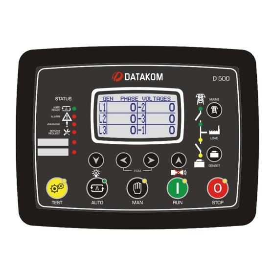
Page 52: Description Of Controls
D-500 User Manual Rev_06 Firmware V-5.8 9. DESCRIPTION OF CONTROLS 9.1. FRONT PANEL FUNCTIONALITY Graphic LCD Mimic Diagram screen (sysem status) AUTO READY Mains Contactor indicator control in RUN mode Fault condition Next display indicators group Genset Next screen in Contactor the same group. -
Page 53: Pushbutton Functions
D-500 User Manual Rev_06 Firmware V-5.8 9.2. PUSHBUTTON FUNCTIONS BUTTON FUNCTION Selects TEST mode. The genset runs and takes the load. Selects RUN mode. The genset runs off-load. Selects AUTO mode. The genset runs when necessary and takes the load. -
Page 54: Display Screen Organization
D-500 User Manual Rev_06 Firmware V-5.8 9.3. DISPLAY SCREEN ORGANIZATION The unit measures a large number of electrical and engine parameters. The display of the parameters is organized as PARAMETER GROUPS and items in a group. Navigation between different groups are made with buttons. -
Page 55: Automatic Display Scroll
D-500 User Manual Rev_06 Firmware V-5.8 9.4. AUTOMATIC DISPLAY SCROLL The unit will automatically scroll all Mains, Genset and Engine measurements with programmable interval. The scroll period setting can be performed using the RainbowPlus program through Module > Screen options. - Page 56 D-500 User Manual Rev_06 Firmware V-5.8 K35D05-EN - 56 -...
-
Page 57: Measured Parameters
D-500 User Manual Rev_06 Firmware V-5.8 9.5. MEASURED PARAMETERS The unit performs a detailed set of AC measurements. Mains currents and power parameters (listed in blue color) are measured and displayed only if CTs are placed at load side. please see connection diagrams section for more details. -
Page 58: Led Lamps
D-500 User Manual Rev_06 Firmware V-5.8 9.6. LED LAMPS AUTO READY Mains indicator available led Mains Shutdown Contactor alarm indicator On led Warning Genset indicator Contactor on led Service request Genset indicator available RUN mode TEST mode AUTO mode STOP mode... -
Page 59: Waveform Display & Harmonic Analysis
D-500 User Manual Rev_06 Firmware V-5.8 10. WAVEFORM DISPLAY & HARMONIC ANALYSIS The unit features waveform display together with a precision harmonic analyzer for both mains and genset voltages and currents. Both phase to neutral and phase to phase voltages are available for analysis, thus 18 channels in total are possible. - Page 60 D-500 User Manual Rev_06 Firmware V-5.8 The harmonic analyzer consists on a Fast Fourier Transform (FFT) algorithm which is run twice a second on the selected channel. The sample memory is 1024 samples length and 13 bits resolution with a sampling rate of 4096 s/s.
-
Page 61: Displaying Event Logs
D-500 User Manual Rev_06 Firmware V-5.8 11. DISPLAYING EVENT LOGS The unit features more than 400 event logs with date-time stamp and full snapshot of measured values at the moment that the event has occurred. Stored values in an event record are listed below:... - Page 62 D-500 User Manual Rev_06 Firmware V-5.8 Event logs are displayed within the program mode menu. This is designed in order to reduce the interference of event logs with other measurement screens. To enter the event display, press together buttons for 5 seconds.
-
Page 63: Statistical Counters
D-500 User Manual Rev_06 Firmware V-5.8 12. STATISTICAL COUNTERS The unit provides a set of non-resettable incremental counters for statistical purposes. The counters consist on: -total genset kWh -total genset kVArh inductive -total genset kVArh capacitive -total genset export kWh... -
Page 64: Fuel Consumption Monitoring
D-500 User Manual Rev_06 Firmware V-5.8 12.2. FUEL CONSUMPTION MONITORING The unit is capable to display the actual fuel consumption of the engine by two different ways: Through J1939 fuel consumption information By counting fuel consumption pulses. If the engine is sending the fuel rate through J1939 messaging, then the unit will directly display the fuel consumption information coming from the ECU. -
Page 65: Operation Of The Unit
D-500 User Manual Rev_06 Firmware V-5.8 13. OPERATION OF THE UNIT 13.1. QUICK START GUIDE STOPPING THE ENGINE: Press STOP button STARTING THE ENGINE: Press RUN button MANUAL LOAD TRANSFER: Use MAINS and GENSET buttons. LOAD TEST: Press TEST button. The genset will run and take the load. -
Page 66: Auto Mode
D-500 User Manual Rev_06 Firmware V-5.8 13.3. AUTO MODE The AUTO mode is entered by pressing the button. The AUTO mode is used for the automatic transfer between genset and mains. The controller will constantly monitor the mains availability. It will run the engine and transfer the load when a mains failure occurs. -
Page 67: Run Mode, Manual Control
D-500 User Manual Rev_06 Firmware V-5.8 13.4. RUN MODE, MANUAL CONTROL The RUN mode is entered by pressing the button. When the RUN mode is selected, the engine will be started regardless of the mains availability. The starting sequence is as described below: ... -
Page 68: Protections And Alarms
D-500 User Manual Rev_06 Firmware V-5.8 14. PROTECTIONS AND ALARMS The unit provides 3 different protection levels, being warnings, loaddumps and shutdown alarms. 1- SHUTDOWN ALARMS: These are the most important fault conditions and cause: The ALARM led to turn on steadily,... -
Page 69: Disabling All Protections
D-500 User Manual Rev_06 Firmware V-5.8 14.1. DISABLING ALL PROTECTIONS The unit allows any digital input to be configured as “Disable Protections”. This input configuration is used in cases where the engine is required to run until destruction. This may be the case under critical conditions like fire fighting or other emergency cases. -
Page 70: Shutdown Alarms
D-500 User Manual Rev_06 Firmware V-5.8 14.3. SHUTDOWN ALARMS Digital input and analog sender alarms are fully programmable for the alarm name, sampling and action. Only internal alarms are explained in this section. GENSET LOW / HIGH Set if the generator frequency is outside programmed limits. These faults will FREQUENCY be monitored with Fault Holdoff Timer delay after the engine is running. -
Page 71: Loaddump Alarms
D-500 User Manual Rev_06 Firmware V-5.8 14.4. LOADDUMP ALARMS Digital input and analog sender alarms are fully programmable for the alarm name, sampling and action. Only internal alarms are explained in this section. VOLTAGE UNBALANCE Set if any of the generator phase voltages differs from the average by more than Voltage Unbalance Limit for Voltage Fail Timer. -
Page 72: Warnings
D-500 User Manual Rev_06 Firmware V-5.8 14.5. WARNINGS Digital input and analog sender alarms are fully programmable for the alarm name, sampling and action. Only internal alarms are explained in this section. All warnings can be made latching by enabling a single program parameter: Controller Configuration >Latch All Warnings... - Page 73 D-500 User Manual Rev_06 Firmware V-5.8 J1939 ECU FAIL Set when an engine fault code is received from the ECU of the electronic engine. This fault will not cause an engine stop. If necessary, the engine will be stopped by the ECU.
-
Page 74: Non-Visual Warnings
D-500 User Manual Rev_06 Firmware V-5.8 14.6. NON-VISUAL WARNINGS These warnings are not announced at the device front panel, however they appear in event logs, transferred to the Scada and cause SMS and e-mail sending. Engine is not running: FUEL THEFT... -
Page 75: Programming
D-500 User Manual Rev_06 Firmware V-5.8 15. PROGRAMMING 15.1. RESETTING TO FACTORY DEFAULTS In order to resume to the factory set parameter values: -hold pressed the OFF, LAMP TEST and ALARM MUTE buttons for 5 seconds, -“RETURN TO FACTORY SET” will be displayed -immediately press and hold pressed RİGHT ARROW button for 5 seconds... -
Page 76: Entering The Programming Mode
D-500 User Manual Rev_06 Firmware V-5.8 The program mode is used to adjust timers, operational limits and the configuration of the unit. Although a free PC program is provided for programming, every parameter may be modified through the front panel, regardless of the operating mode. -
Page 77: Navigating Between Menus
D-500 User Manual Rev_06 Firmware V-5.8 15.3. NAVIGATING BETWEEN MENUS The program mode is driven with a two level menu system. The top menu consists on program groups and each group consists on various program parameters. When program mode is entered, a list of available groups will be displayed. Navigation between different ▲... -
Page 78: Modifying Parameter Value
D-500 User Manual Rev_06 Firmware V-5.8 15.4. MODIFYING PARAMETER VALUE Decrease Increase parameter parameter value value Previous parameter Long Press: Next Return to the parameter upper menu 15.5. PROGRAMMING MODE EXIT To exit the program mode press one of the mode selection keys. If no button is pressed during 2 minutes the program mode will be cancelled automatically. -
Page 79: Program Parameter List
D-500 User Manual Rev_06 Firmware V-5.8 16. PROGRAM PARAMETER LIST 16.1. CONTROLLER CONFIGURATION GROUP Parameter Definition Unit Factory Description This parameter is used to set LCD LCD Contrast contrast. Adjust for the best viewing angle. The screen will scroll between different measurements with this interval. - Page 80 Delayed Simulate Mains 1: delayed simulate mains enabled 0: no MODEM / no GPS 1: Internal MODEM, no GPS 2: External Datakom MODEM, no GPS Modem / GPS Selection 3: External generic MODEM, no GPS 4: no MODEM, RS-232 GPS...
- Page 81 D-500 User Manual Rev_06 Firmware V-5.8 16.1. CONTROLLER CONFIGURATION GROUP (continued) Factory Description Parameter Definition Unit 0: RS-485 port disabled RS-485 Enable 1: RS-485 port enabled This is the modbus controller identity Modbus Address used in Modbus communication. This is the data rate of the RS-485...
- Page 82 D-500 User Manual Rev_06 Firmware V-5.8 16.1. CONTROLLER CONFIGURATION GROUP (continued) Parameter Definition Unit Factory Description This parameter controls SMS sending when mains voltages status is changed. SMS on Mains Change No warnings generated. 0: no SMS on mains failed or restored...
- Page 83 D-500 User Manual Rev_06 Firmware V-5.8 16.1. CONTROLLER CONFIGURATION GROUP (continued) Factory Description Parameter Definition Unit Internal buzzer control (not functional in D-500) Buzzer Enable 0: buzzer disabled 1: buzzer enabled 0: AMF functionality. The unit controls both engine and load transfer. The genset starts based on mains status.
- Page 84 D-500 User Manual Rev_06 Firmware V-5.8 16.1. CONTROLLER CONFIGURATION GROUP (continued) Factory Description Parameter Definition Unit This is the number of pulses produced by the flowmeter for the unit volume. Fuel Pulses per Volume 65000 1000 This parameter is characteristic of the flowmeter used and should be set according to the flowmeter data.
- Page 85 D-500 User Manual Rev_06 Firmware V-5.8 16.1. CONTROLLER CONFIGURATION GROUP (continued) Factory Description Parameter Definition Unit 0: no location information from GSM GSM Location 1: location information read from GSM Information system. 0: When Loaddump alarm occurs, genset contactor opens and genset...
-
Page 86: Electrical Parameters Group
D-500 User Manual Rev_06 Firmware V-5.8 16.2. ELECTRICAL PARAMETERS GROUP Parameter Definition Unit Factory Description This is the rated value of current Current Transformer transformers. All transformers must 5000 Primary have the same rating. The secondary of the transformer will be 5 Amps. - Page 87 D-500 User Manual Rev_06 Firmware V-5.8 16.2. ELECTRICAL PARAMETERS GROUP (continued) Parameter Definition Unit Factory Description If the mains phase voltages are outside limits, but not more than this parameter (with reference to nominal voltage), then the genset will run without releasing the mains contactor.
- Page 88 D-500 User Manual Rev_06 Firmware V-5.8 16.2. ELECTRICAL PARAMETERS GROUP (continued) Parameter Definition Unit Factory Description If the genset frequency goes under this Genset Low Frequency limit when feeding the load, this will F-100 F+100 V-15% Warning Limit generate a GENSET LOW FREQUENCY warning.
- Page 89 D-500 User Manual Rev_06 Firmware V-5.8 16.2. ELECTRICAL PARAMETERS GROUP (continued) Parameter Definition Unit Factory Description If any genset phase current differs from the average more than this limit, it will generate a Current Unbalance fault Genset Current condition. The action taken upon fault Unbalance Limit condition is programmable.
- Page 90 D-500 User Manual Rev_06 Firmware V-5.8 16.2. ELECTRICAL PARAMETERS GROUP (continued) Parameter Definition Unit Factory Description If the total genset active power goes over this limit when feeding the load, this will Genset Overload Limit 50000 generate a genset overload loaddump alarm.
- Page 91 D-500 User Manual Rev_06 Firmware V-5.8 16.2. ELECTRICAL PARAMETERS GROUP (continued) Parameter Definition Unit Factory Description This is the period after the generator contactor has been deactivated and Mains Contactor Timer before the mains contactor has been activated. After the mains MCB_undervoltage coil...
- Page 92 D-500 User Manual Rev_06 Firmware V-5.8 16.2. ELECTRICAL PARAMETERS GROUP (continued) Parameter Definition Unit Factory Description 0: shutdown alarm GCB Alarm Level 1: loaddump alarm If a genset MCB feedback input is defined and if the genset MCB fails to...
-
Page 93: Engine Parameters Group
D-500 User Manual Rev_06 Firmware V-5.8 16.3. ENGINE PARAMETERS GROUP Parameter Definition Unit Factory Description The nominal value of engine rpm. Low- Nominal RPM 50000 1500 high rpm limits are defined by reference to this value. When secondary frequency is selected, this is the nominal value of engine rpm. - Page 94 D-500 User Manual Rev_06 Firmware V-5.8 16.3. ENGINE PARAMETERS GROUP (continued) Parameter Definition Unit Factory Description If the charge alternator voltage goes Charge Voltage Fail under limits during this timer, a charge Timer alternator voltage fault will occur. If it is requested that the engine runs...
- Page 95 D-500 User Manual Rev_06 Firmware V-5.8 16.3. ENGINE PARAMETERS GROUP (continued) Parameter Definition Unit Factory Description When the engine runs, the Idle output relay function will be active during this Idle Speed (Run) Timer timer. While the IDLE output is active, low voltage, low frequency and low rpm checks are disabled.
- Page 96 D-500 User Manual Rev_06 Firmware V-5.8 16.3. ENGINE PARAMETERS GROUP (continued) Parameter Definition Unit Factory Description If the coolant temp is above this limit then °C Coolant Cooler On the cooler relay function will become active. If the coolant temp is below this limit then °C...
- Page 97 D-500 User Manual Rev_06 Firmware V-5.8 16.3. ENGINE PARAMETERS GROUP (continued) Parameter Definition Unit Factory Description The SERVICE REQUEST led indicator will turn on after this quantity of engine hours from the last service. If the period Service-2 Engine Hours...
- Page 98 D-500 User Manual Rev_06 Firmware V-5.8 16.3. ENGINE PARAMETERS GROUP (continued) Parameter Definition Unit Fact.Set Description GENERIC ENGINE BRAND 0: Generic CUMMINS ENGINE 0: CM850 1: CM570 DETROIT DIESEL ENGINE 0: Generic DEUTZ ENGINE 0: Generic 1: EMR2 2: EMR3...
- Page 99 D-500 User Manual Rev_06 Firmware V-5.8 16.3. ENGINE PARAMETERS GROUP (continued) Parameter Definition Unit Factory Description This parameter adjusts the speed of an J1939 Speed Adjust -100 +100 ECU controlled engine by +/- 8%. If the air inlet temperature measured...
-
Page 100: Adjust Date And Time
D-500 User Manual Rev_06 Firmware V-5.8 16.4. ADJUST DATE AND TIME These parameters allow adjusting the battery backup real time clock of the module. Once set, the clock will continue to run even if DC power is removed from the unit. -
Page 101: Exerciser Schedule
D-500 User Manual Rev_06 Firmware V-5.8 16.6. EXERCISER SCHEDULE The unit provides 7 independent automatic exerciser programs. Automatic exercise may be done in weekly or monthly basis. If monthly exercise is selected, the week, day and hour is adjustable for each exercise item. -
Page 102: Sender Configuration
D-500 User Manual Rev_06 Firmware V-5.8 16.7. SENDER CONFIGURATION The unit has 4 analog sender inputs. Only parameters of one sender are explained below. Other senders have identical parameter set. Each sender has 16 step programmable curves. The sender name and reading unit is freely programmable, thus the sender can be adapted to any type through programming. - Page 103 D-500 User Manual Rev_06 Firmware V-5.8 Factory Description Parameter Definition Unit Sender Curve-1 ohm ohms 5000 Point-1 ohm value Sender Curve-1 value 10000 Point-1 reading Sender Curve-2 ohm ohms 5000 Point-2 ohm value Sender Curve-2 value 10000 Point-2 reading Sender Curve-3 ohm...
-
Page 104: Digital Input Configuration
D-500 User Manual Rev_06 Firmware V-5.8 16.8. DIGITAL INPUT CONFIGURATION The unit has 8 digital inputs. By using external input extension modules, up to 40 inputs in total are available. Only parameters of one input are explained below. Other inputs have identical parameter set. - Page 105 D-500 User Manual Rev_06 Firmware V-5.8 INPUT FUNCTION LIST Description Description Description User Defined Function Over Resonance Low Oil Press. Switch Short-Circuit Alarm High Temp. Switch Reset Service 1 Alm Coolant Level Switch Reset Service 2 Alm Rectifier Fail Switch...
-
Page 106: Output Configuration
D-500 User Manual Rev_06 Firmware V-5.8 16.9. OUTPUT CONFIGURATION The parameters below define the functions of relay outputs. The unit has 8 relay outputs. All relays have programmable functions, selected from a list. Relays may be extended up to 40 using Relay Extension Modules.. Other relays are in the optional Extension Modules. - Page 107 D-500 User Manual Rev_06 Firmware V-5.8 OUTPUT FUNCTION LIST Description Description Description Fuel Pgm Mode Active Remote Control Out 11 Horn Engine Running Remote Control Out 12 Crank Genset Voltage Ok Remote Control Out 13 Stop Solenoid Alarm Check Enable...
-
Page 108: Site Id String
D-500 User Manual Rev_06 Firmware V-5.8 16.10. SITE ID STRING The site identity string is designed to identify the current controller. This is the site Id string sent at the beginning of SMS messages, e-mails and web page headers for the identification of the genset sending the message. -
Page 109: Gsm Modem Parameters
D-500 User Manual Rev_06 Firmware V-5.8 16.13. GSM MODEM PARAMETERS Parameter Definition Description The APN (access point name) username may be required by the GSM operator. However some GSM operators may allow access without APN User Name username. The exact information should be obtained from the GSM operator. -
Page 110: Ethernet Parameters
D-500 User Manual Rev_06 Firmware V-5.8 16.14. ETHERNET PARAMETERS Parameter Definition Factory Set Description This is the IPv4 (internet protocol version 4) address that the unit will require from the DHCP (dynamic host control protocol) server. Network IP Address 0.0.0.0 If this parameter is set to 0.0.0.0 then the unit will... - Page 111 Factory Set Description This is the account name appearing in the “from” tab Mail Account Name d500_a of the e-mail recipient. (ex: datakom-d500@gmail.com) Mail Account d500_1234 This is the e-mail password of above e-mail account. Password This is the Outgoing Mail Server Address of the above Mail Server Address smtp.mail.yahoo.com...
-
Page 112: Sntp Parameters
D-500 User Manual Rev_06 Firmware V-5.8 16.15. SNTP PARAMETERS SNTP (simple network time protocol) communication allows the controller to querry high precision, atomic clock based date/time servers through the internet and to adjust its internal real time clock to these servers. -
Page 113: Crank Cutting
D-500 User Manual Rev_06 Firmware V-5.8 17. CRANK CUTTING In order to insure fast and reliable crank cutting, the unit uses various resources for engine running condition detection. Cranking is stopped when at least one of below conditions is met: - Crank timer expired: The crank timer is adjusted through Engine Parameters >... -
Page 114: Overcurrent Protection (Idmt)
D-500 User Manual Rev_06 Firmware V-5.8 18. OVERCURRENT PROTECTION (IDMT) The unit offers a programmable IDMT protection function in order to protect the alternator against excessive currents. The IDMT (Inverse Definite Minimum Time) protection function has such tripping characteristics that the tripping time varies inversely with the value of current. - Page 115 D-500 User Manual Rev_06 Firmware V-5.8 Below is a table showing the tripping delay in function of the percent load level (with TMS=36): 100% unlimited 170% 73s 240% 18s 110% 3600s 180% 56s 250% 16s 120% 900s 190% 44s 260% 14s...
-
Page 116: Motorized Circuit Breaker Control
D-500 User Manual Rev_06 Firmware V-5.8 19. MOTORIZED CIRCUIT BREAKER CONTROL The unit offers full control for any brand and model of motorized circuit breakers (MCB). The MCB control is performed through 3 digital output functions, namely Open, Close and Undervoltage coil controls. - Page 117 D-500 User Manual Rev_06 Firmware V-5.8 MCB modules can be operated by 2 different ways. The unit supports both configurations. Below is the terminology used: M: gear motor PF: ready to close contact XF: close coil MX: open coil MN: undervoltage trip (release)
-
Page 118: J1939 Canbus Engine Support
Type parameter should be set accordingly. The list of available engines is given at the programming section. Please contact DATAKOM for the most current list of engines. If the J1939 port is enabled then the oil pressure, coolant temperature and the engine rpm information are picked up from the ECU unit. - Page 119 D-500 User Manual Rev_06 Firmware V-5.8 The electronic engine fault codes are displayed in text within the alarm list table, together with their SPN-FMI codes. The complete list of fault codes is given in the engine manufacturer’s user manual. Below is a basic list of fault conditions (x denotes any FMI)
- Page 120 D-500 User Manual Rev_06 Firmware V-5.8 DESCRIPTION Incorrect ECM software Engine magnetic speed sensor fault ECU internal +5V fail Preheating relay fault Injector power supply fault ECU hardware fail ECU memory fail Fuel injector valve fault Camshaft sensor Flywheel sensor ECU memory fail External speed comm.
- Page 121 D-500 User Manual Rev_06 Firmware V-5.8 Below is a basic list of FMI codes. Please be aware that these codes may differ slightly depending on the engine brand and model. DESCRIPTION Value too high” Valid data, but above the normal working range “Value too low”...
-
Page 122: Gps Support
Firmware V-5.8 21. GPS SUPPORT The unit supports external GPS modules from both RS-232 and USB-Host ports. USB GPS modules can be procured from Datakom or from the free market. RS-232 GPS modules are available at Datakom. DATAKOM RS-232 GPS MODULE... - Page 123 D-500 User Manual Rev_06 Firmware V-5.8 The GPS location determination is based on signals transmitted by GPS satellites circulating in earth’s orbit. 24 satellites are available in total, but the number of satellites in sight will depend on the physical location and time.
-
Page 124: Ethernet Configuration
Please see related document: GSM Configuration Guide for D-500 D-700. 24. DYNAMIC DNS FEATURE Please see related document: Dynamic DNS Account Setting for D-500 D-700. 25. ACCESSING THE EMBEDDED WEB SERVER Please see related document: Ethernet Configuration Guide for D-500 D-700. -
Page 125: Sms Commands
D-500 User Manual Rev_06 Firmware V-5.8 29. SMS COMMANDS SMS messages are accepted only from phone numbers recorded in the Communication>GSM>Message Numbers tab. Answers to SMS messages will be sent to all phone numbers in the list. SMS messages must be written exactly as below, without any preceding blanks. - Page 126 D-500 User Manual Rev_06 Firmware V-5.8 COMMAND DESCRIPTION ANSWER Puts the controller into STOP mode. Alarms MODE STOP Unit forced to STOP! are also cleared. Puts the controller into AUTO mode. Alarms MODE AUTO Unit forced to AUTO! are also cleared.
-
Page 127: Load Transfer Modes
D-500 User Manual Rev_06 Firmware V-5.8 30. LOAD TRANSFER MODES The unit offers 2 ways of transferring the load from genset to mains and vice versa: -transfer with interruption, -no break transfer, (with or without synchronization) 30.1. TRANSFER WITH INTERRUPTION This is the most conventional way of transferring the load between the genset and mains. -
Page 128: Uninterrupted Transfer
D-500 User Manual Rev_06 Firmware V-5.8 30.2. UNINTERRUPTED TRANSFER In this mode, the transfer will be made without power interruption. This implies that both of the mains and generator contactors will be active during transfer. The maximum duration that both contactors will be active is programmable. However this process may be quicker with the use of one auxiliary feedback contact from each contactor. -
Page 129: Data Recording
D-500 User Manual Rev_06 Firmware V-5.8 31. DATA RECORDING 31.1. DATA RECORDING MEDIA Data can be recorded in USB flash memory or MICRO-SD memory card. Both options are available. As soon as a USB flash memory or a MICRO-SD card is inserted, the unit will start data recording and continue until the memory is removed. -
Page 130: Directory Structure
D-500 User Manual Rev_06 Firmware V-5.8 31.2. DIRECTORY STRUCTURE The unit will record data in either an USB-Flash memory or a micro-SD flash memory card. The record structure is the same in both cases. Last day of SITE-ID Year 2012... -
Page 131: Recorded Data List, Record Period
D-500 User Manual Rev_06 Firmware V-5.8 31.4. RECORDED DATA LIST, RECORD PERIOD The recording period is adjustable between 2 seconds and 18 hours by program parameter. A short period will give better resolution, but it will generate more data in the memory card. -
Page 132: Software Features
D-500 User Manual Rev_06 Firmware V-5.8 32. SOFTWARE FEATURES 32.1. LOAD SHEDDING / DUMMY LOAD The load shedding feature consists on the disconnection of the least crucial loads when the genset power approaches to its limits. These loads will be supplied again when the genset power falls below the programmed limit. -
Page 133: Load Add / Substract
D-500 User Manual Rev_06 Firmware V-5.8 32.2. LOAD ADD / SUBSTRACT The load add/subtract output functions are designed to provide control signals for an external, multi-step load adding/substracting system. This external system will add either linearly or by small steps a dummy load that will prevent the genset from running below the minimum required load level. -
Page 134: Five Step Load Management
D-500 User Manual Rev_06 Firmware V-5.8 32.3. FIVE STEP LOAD MANAGEMENT The controller is able to manage the supply of up to 5 prioritized loads. The loads are supplied starting from the number #1 (highest priority) and unloaded from the highest number (lowest priority) available. -
Page 135: Remote Start Operation
D-500 User Manual Rev_06 Firmware V-5.8 32.4. REMOTE START OPERATION The unit offers the possibility of Remote Start mode of operation. Any digital input may be assigned as Remote Start Input using Input Function Select program parameters. The Remote Start signal may be a NO or NC contact, switching to either battery positive or battery negative. -
Page 136: Battery Charging Operation, Delayed Simulate Mains
D-500 User Manual Rev_06 Firmware V-5.8 32.6. BATTERY CHARGING OPERATION, DELAYED SIMULATE MAINS The Delayed Mains Simulation feature is used in battery backed up telecom systems where batteries are able to supply the load during a certain period. The genset is requested to run only when battery voltage drops below the critical level. -
Page 137: Dual Genset Mutual Standby Operation
If a Priority input is defined, then the system will work in priority mode. If the priority signal is applied, the unit will become master after each mains failure. If the priority signal is not applied, then the unit will become the slave one and the other genset will start. Please contact DATAKOM for a complete application manual. K35D05-EN... -
Page 138: Multiple Voltage And Frequency
D-500 User Manual Rev_06 Firmware V-5.8 32.8. MULTIPLE VOLTAGE AND FREQUENCY The unit offers 3 sets of voltage and frequency protection limit values. The user is allowed to switch between these 3 sets anytime. This feature is especially useful in multiple voltage or frequency gensets for easy switching between different operating conditions. -
Page 139: Automatic Exerciser
D-500 User Manual Rev_06 Firmware V-5.8 32.11. AUTOMATIC EXERCISER The unit offers 7 independent automatic exercisers. The exercise operation may be done on a weekly or monthly basis. The start day and time of the exercise is programmable as well as its duration. The exercise may be done with or without load following programming. -
Page 140: Engine Heating Operation
D-500 User Manual Rev_06 Firmware V-5.8 32.13. ENGINE HEATING OPERATION Especially on engines without a body heater, or with a failing one, it may be desired that the genset should not take the load before reaching a suitable temperature. The unit offers 2 different ways of engine heating. -
Page 141: Fuel Pump Control
D-500 User Manual Rev_06 Firmware V-5.8 32.16. FUEL PUMP CONTROL The unit is able to provide a digital output function in order to drive the fuel pump motor. The fuel pump is used to transfer fuel from the large capacity main tank (if exists), to the genset daily tank which is generally integrated in the chassis and has a limited capacity. -
Page 142: Charging The Engine Battery
D-500 User Manual Rev_06 Firmware V-5.8 32.19. CHARGING THE ENGINE BATTERY The controller offers an automatic charge cycle for the engine battery. When the engine battery weakens, the genset will run automatically during programmed period in an unloaded state in order to charge the engine battery, protecting it from total discharge when the genset has not run for a long time. -
Page 143: Resetting The Controller
D-500 User Manual Rev_06 Firmware V-5.8 32.22. RESETTING THE CONTROLLER When necessary, the controller may be manually reset by holding the STOP button pressed for 30 seconds. The manual reset will cause the hardware to be configured following new settings. -
Page 144: Zero Power At Rest
D-500 User Manual Rev_06 Firmware V-5.8 32.24. ZERO POWER AT REST In a manual genset, it is possible to reduce the current consumption of the unit down to true zero Amperes, in order to prevent the battery from discharging. For “zero power at rest operation”, an external relay and “wake-up” pushbutton is necessary. -
Page 145: Modbus Communications
D-500 User Manual Rev_06 Firmware V-5.8 33. MODBUS COMMUNICATIONS This chapter is a brief description of the Modbus properties of the controller. For a complete documentation please use “D- 500 D-700 Modbus Application Manual” The unit offers the possibility of MODBUS communication through below carriers:... -
Page 146: Parameters Required For Rs-485 Modbus Operation
Ethernet Subnet Mask: Should be set in accordance with your local switch configuration. The complete Ethernet port specifications are found in the D-500/700 User Manual. Please rewiev the document Ethernet Configuration Guide for D-500/700 for more details about the ethernet port setup. - Page 147 D-500 User Manual Rev_06 Firmware V-5.8 Below is a shortlist of available Modbus registers. For complete register map please refer to D-500/700 Modbus Application Manual. ADDRESS R / W DATA COEFF. DESCRIPTION (decimal) SIZE 8193 16bit Pushbutton simulation BIT 0.Simulate Stop button BIT 1.Simulate Manual button...
- Page 148 D-500 User Manual Rev_06 Firmware V-5.8 ADDRESS R / W DATA COEFF. DESCRIPTION (decimal) SIZE 10504- 256bit Shutdown alarm bits. Bit definitions are given at the end of the 10519 document. 10520- 256bit Loaddump alarm bits. Bit definitions are given at the end of the 10535 document.
-
Page 149: Snmp Communications
Shutdown Alarm List Genset Power Factor (L1, L2, L3, Total) Loaddump Alarm List Genset Phase Angle Warning Alarm List Genset Frequency Genset Operation Mode Remote Controlled Digital Outputs The SNMP MIB file is available at Datakom Technical support. K35D05-EN - 149 -... -
Page 150: Snmp Trap Messages
Ethernet Subnet Mask: Should be set in accordance with your local switch configuration. The complete Ethernet port specifications are found in the D-500/700 User Manual. Please rewiev the document Ethernet Configuration Guide for D-500/700 for more details about the ethernet port setup. - Page 151 “Monitoring and control instruments including industrial monitoring and control instruments” and exempted from ROHS directive. However Datakom is not using any ROHS uncompliant electronic components in the production. Only the solder contains lead. The switching to unleaded solderin is in progress. K35D05-EN...
- Page 152 D-500 User Manual Rev_06 Firmware V-5.8 39. TROUBLESHOOTING GUIDE Below is a basic list of most often encountered troubles. More detailed investigation may be required in some cases. The genset operates while AC mains are OK or continues to operate after AC mains are OK: -Check engine body grounding.
- Page 153 D-500 User Manual Rev_06 Firmware V-5.8 The engine does not run after the first start attempt, then the unit does not start again and OIL PRESSURE EXISTS ! message is displayed: -The oil pressure switch closes very lately. As the unit senses an oil pressure, it does not start. When oil pressure switch closes the unit will start.
Need help?
Do you have a question about the D-500 and is the answer not in the manual?
Questions and answers
L alarmed rouge s allume
When the ALARM LED is on for the Datakom D-500, it means there is a shutdown alarm or a loaddump condition present.
This answer is automatically generated