Table of Contents
Advertisement
Quick Links
Advertisement
Table of Contents

Related Manuals for XS Vio OXY 70

Summary of Contents for XS Vio OXY 70
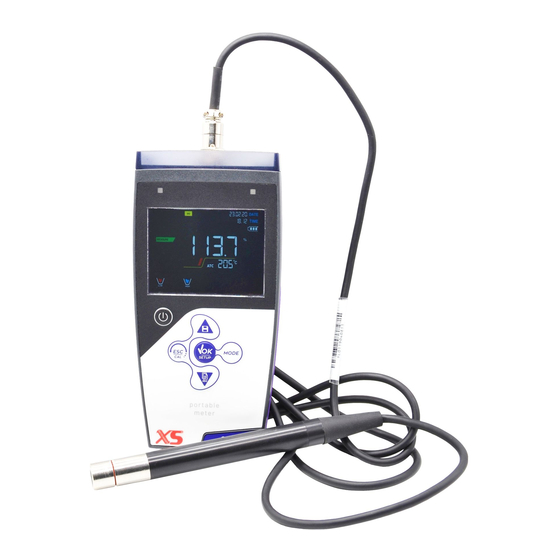
- Page 1 OXY 70 Vio – mg/l – mbar - Temp INSTRUCTIONS MANUAL Rev 1.0 26/02/2020...
- Page 2 Rev 1.0 26/02/2020...
-
Page 3: Table Of Contents
Index ................................. 1 Introduction ............................. 5 Safety information ........................... 6 • Definitions of warning words and symbols ..................6 • Reporting terms: ..........................6 • Additional documents for safety ......................7 • Use according to destination ....................... 7 Basic requirements for a safe use ....................... 7 •... - Page 4 Composition of the setup menu for Setting menu ................25 DataLink+ Software (per Windows 7/8/XP/10) .................27 • Functions ............................27 Warranty ............................28 Warranty period and limitations .......................28 • Disposal of electrical devices ......................28 XS Instruments Via della Meccanica n.25 41012 Carpi (MO) ITALY Tel.+39059.653274 Fax +39059653282 www.xsinstruments.com...
-
Page 5: Introduction
Introduction XS Instruments, globally recognized as a leading brand in the field of electrochemical measurements, has developed this new line of portable instruments completely produced in Italy, finding the perfect balance between performance, attractive design and ease of use. The robustness and integrity of the case, the integrated brightness sensor and the practical carrying case make this instrument ideal for measurements directly in the field. -
Page 6: Safety Information
Safety information • Definitions of warning words and symbols This manual contains extremely important safety information, in order to avoid personal injury, damage to the instrument, malfunctions or incorrect results due to failure to comply with them. Read entirely and carefully this manual and be sure to familiarize with the tool before starting to work with it. -
Page 7: Additional Documents For Safety
• Additional documents for safety The following documents can provide the operator with additional information to work with the measuring system safely: • operating manual for electrochemical sensors; • safety data sheets for buffer solutions and other maintenance solutions (e.g. storage); •... -
Page 8: Responsibility Of The Owner Of The Instrument
If liquids get into the housing, they could damage the instrument. Do not open the instrument housing: it does not contain parts that can be maintained, repaired or replaced by the user. In case of problems with the instrument, contact your local distributor. It is recommended to use original spare parts only. -
Page 9: Instrument Description
Accuracy ± 0,5% Automatic temperature compensation ATC Temperature Measuring range -10,0…110,0 °C Resolution ± 0,1°C Accuracy ± 0,5°C Temperature compensation ATC and Yes, automatic only Salinity Measuring range 0…50 ppt Salinity compensation Si, manuale System GLP with calibration Timer Internal memory 1000 Data Display High definition colour LCD... -
Page 10: Keyboard
• Keyboard On-Off button to switch the device on Up directional key for scrolling and off through menus and parameters and managing data saving Meas / Cal key to return to measure mode and to start calibration MODE key to scroll through the various measurement parameters Enter / Menu key to confirm the chosen values and enter the setup from the measure mode... -
Page 11: Start-Up
• Start-up • The device leaves the factory ready to be used by the user. Batteries are included. • • Connection of the power supply • in addition to batteries, the instrument can be powered through electricity grid; check that the electrical standards of the line on which the instrumentation is to be installed •... -
Page 12: Replacement Of Batteries
• Replacement of batteries The instrument works with 3 AA 1.5V batteries. To proceed with the replacement: 1. Turn off the device. 2. Turn the instrument over with the display facing down and place it on a stable surface. It is advisable to put a cloth to avoid any scratching on display. 3. -
Page 13: Inputs / Outputs Connections
In measure mode, keep one of the two keys pressed to change the temperature in MTC mode (manual compensation, without probe). When the value starts to flash, the user can change the temperature value by entering the correct one and Long-press (3s) confirming with... -
Page 14: Operation Of The Device
FIXED: Calibration deadline set for that Press the directional keys to change parameter the parameter or value on the INTERMITTENT: Calibration deadline display active for that parameter Measurement stability indicator Battery charge indication The bars scroll if the measurement is not stable Operation of the device After the switching on, the instrument enters measure mode in the last screen before turning off. -
Page 15: Setup Menu
String Meaning The instrument is in measure mode. The instrument is in calibration (automatic or manual in relation to the user's choice). The user is in the setup mode. The configuration menus can concern the characteristics of the parameters or the general setting of the instrument. The instrument is in the Recall Memory mode. -
Page 16: Setup Menu Structure
• Press the key to return to the previous menu. • Setup Menu Structure P5.0 DO SETTINGS P5.1 Cal 0 P5.2 Salt Compensation P5.6 Cal Data P5.7 Set Due Cal P5.8 Reset Settings P5.9 Temp Cal P8.0 LOG SETTINGS P8.1 Data Logger Type P8.2 Clear Data... -
Page 17: O 2 Parameter
Parameter Connect the optical sensor to the 6-pole multipin connector. It is not necessary connect an external temperature probe, because it is already integrated. Connettere il sensore ottico al connettore di tipo Multipin 6 poli. Once switched on, the device does not require any polarization time. There, it is ready for use (calibration and/or measurement). - Page 18 Access this menu to get information on the last performed calibration. The following screens will automatically scroll on the display: • First screen: Beakers indicating the points (0% - 100% O ) on which the calibration was performed. • Second screen: OFFSET value of the sensor expressed in %. •...
-
Page 19: Information About Ldo70 Probe
• Information about LDO70 probe The LDO70 probe uses a luminescence optical technology for dissolved oxygen measurements in water. This type of probe has many advantages compared to classical polarographic type sensor, some of these are: • Zero polarization time, the instrument is always ready •... -
Page 20: Calibration With Zero Oxygen Standard
• Place the probe in air with the membrane facing downwards and wait for 2 minutes. Then, connect the sensor to the device. • In measure mode, press the key to enter in calibration mode. On the display, it appears the string “POINT oxy 100.0”; the device will look for the value %O = 100 %. -
Page 21: Calibration Range
ATTENTION: Before proceeding with the calibration operations, carefully consult the safety data sheets of the substances involved: • Zero oxygen Standard calibration solution Note: The Zero Oxygen Standard Solution is SINGLE DOSE! After its use, contact your local distributor for the purchase. -
Page 22: Performing The Measurement
Dissolved O Saturation expressed in % • Dissolved Concentration expressed mg/l, corresponding • mg/l = ppm Barometric pressure • • During the measurement press the button , in order to change the unit of measurement. • Performing the measurement Remove the protective cap of electrode, rinse it with distilled water; dab it with paper towel and dip in the solution to analyse. -
Page 23: Data Logger Function
After the maintenance make a new Calibration of the oxygen sensor. Data Logger Function This series of devices has the possibility of recording values in GLP format on the instrument's internal memory. • The instrument can save up to 1000 data in total. Once the memory is finished, the values are NOT overwritten. -
Page 24: Example Of Automatic Data Logger Mode
indicated by the icon , change the value of the acquisition time. Confirm the setting with the key • Use of automatic Data Logger • In measure mode press to start and end automatic recording. • When the automatic data saving is running, the icon flashes on the display. -
Page 25: Recall Memory
• Recall Memory • In measure mode in the parameter of interest, press key to enter the RECALL MEMORY mode. The last saved data is shown on the display. • As indicated by the string , use the directional keys to scroll through the different stored values. The number next to the M+ icon indicates the save slot. - Page 26 °C -default- • • °F P9.2 Date and time setting Access this setup menu to update the device date and time. Use the directional keys to change the year, confirm with and repeat the same operation for month, day, hours and minutes. P9.3 Backlight Mode Access this setup menu to select the contrast mode to use for the display backlight: INDOOR (In) –...
-
Page 27: Datalink+ Software (Per Windows 7/8/Xp/10)
NOTE: Auto-switch-off of the instrument is disabled, if data is being recorded with the automatic Data Logger mode IMPORTANT: The correct and systematic use of parameters P9.3 / P9.4 / P9.5 / P9.9 allows to significantly lengthen battery life. DataLink+ Software (per Windows 7/8/XP/10) It is possible to connect the instruments of the 70 Vio series to the PC and then use the DataLink + 1.6 software (and later versions) to perform data download, Data Logger directly on PC and exports in .xls (Excel) -
Page 28: Warranty
Warranty • Warranty period and limitations • The manufacturer of this device and its accessories offers the final consumer of the new device the five-year warranty from the date of purchase, in the event of state-of-the-art maintenance and use. • During the warranty period, the manufacturer will repair or replace defective components.