MIR 250 User Manual
Hide thumbs
Also See for MIR 250:
- User manual (219 pages) ,
- Technical manual (79 pages) ,
- Quick start manual (56 pages)
Table of Contents
Advertisement
Quick Links
Advertisement
Table of Contents

Related Manuals for MIR MIR 250


Summary of Contents for MIR MIR 250
- Page 1 User Guide (en) Date: 07/2020 Revision: v.1.1...
- Page 2 All rights reserved. No parts of this manual may be reproduced in any form without the express written permission of Mobile Industrial Robots A/S (MiR). MiR makes no warranties, expressed or implied, in respect of this document or its contents. In addition, the contents of the document are subject to change without prior notice.
-
Page 3: Table Of Contents
2.4 How MiR250 Shelf Carrier works 3. Accessing the internal parts 3.1 Front compartment 3.2 Rear compartment 3.3 Side compartments 3.4 MiR Shelf Carrier 250 4. Safety 4.1 Safety message types 4.2 General safety precautions 4.3 Intended use 4.4 Users 4.5 Foreseeable misuse... - Page 4 5.2 Unpacking MiR250 Shelf Carrier 5.3 Connecting the battery and powering up 5.4 Connecting to the robot interface 5.5 Driving the robot in Manual mode 5.6 Moving the robot by hand 5.7 Checking the hardware status 5.8 Mounting the nameplate 5.9 Enable MiR250 Shelf Carrier feature 5.10 Testing the top application 5.11 Shutting down the robot...
- Page 5 7.11 System overview 7.12 Collision avoidance 7.13 Overspeed avoidance 7.14 Stability 7.15 Emergency stop buttons 7.16 MiR Shelf Carrier 250 safety functions 7.17 Light indicators and speakers 8. Commissioning 8.1 Analysis of the work environment 8.2 Risk assessment 8.3 Shelf specifications 8.4 Creating and configuring a map...
- Page 6 8.14 Creating backups 8.15 System settings 9. Usage 9.1 Creating the Prompt user mission 9.2 Creating the Try/Catch mission 9.3 Creating the Variable footprint mission 9.4 Creating the 80 cm doorway mission 9.5 Creating the Pick up and place shelf mission 9.6 Creating the Place shelf at VL-marker mission 9.7 Testing a mission 10.
- Page 7 16. Error handling 16.1 Software errors 16.2 Hardware errors MiR250 Shelf Carrier User Guide (en) 07/2020 - v.1.1 ©Copyright 2020: Mobile Industrial Robots A/S.
-
Page 8: About This Document
• The MiR network and WiFi guide specifies the performance requirements of your network and how you must configure it for MiR robots and MiR Fleet to operate successfully. MiR250 Shelf Carrier User Guide (en) 07/2020 - v.1.1 ©Copyright 2020: Mobile Industrial Robots A/S. -
Page 9: Version History
1. About this document 1.2 Version history This table shows current and previous versions of this document. Revision Release date Description 2020-06-26 First edition 2020-07-01 Minor corrections throughout manual. MiR250 Shelf Carrier User Guide (en) 07/2020 - v.1.1 ©Copyright 2020: Mobile Industrial Robots A/S. -
Page 10: Product Presentation
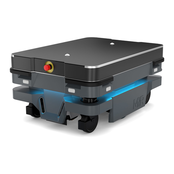
2. Product presentation 2. Product presentation MiR250 Shelf Carrier is an autonomous mobile robot with a top module mounted to it. It is designed to transport wheeled shelves indoors within production facilities, warehouses, and other industrial locations where access to the public is restricted. Users operate MiR250 Shelf Carrier via a web-based user interface, which is accessed via a browser on a PC, smartphone, or tablet. -
Page 11: Main Features Of Mir250 Shelf Carrier
The payload includes both the weight of the shelf itself and the load on the shelf. Specifications for MiR250 Shelf Carrier are available on the MiR website. 2.1 Main features of MiR250 Shelf Carrier The main features of the MiR250 Shelf Carrier are: •... - Page 12 2. Product presentation • Automatic deceleration for objects The built-in sensors ensure that the robot is slowed down when obstacles are detected in front of it. • Internal map The robot can either use a floor plan from a CAD drawing, or a map can be created by manually driving the robot around the entire site in which the robot is going to operate.
-
Page 13: External Parts
2. Product presentation 2.2 External parts This section presents the parts of MiR250 Shelf Carrier that are visible on the outside. Pos. Description Pos. Description Corner bumper: four pcs, one Front cover: opens to front on each corner compartment—see Internal parts on page 19 Swivel wheel with foot guard: 3D depth camera: two pcs,... - Page 14 The identification label of MiR250 is located on the rear cover next to the battery, and the identification label of MiR Shelf Carrier 250 is located on the frame beneath its cover. Figure 2.1. Example of a MiR250 Shelf Carrier identification label.
- Page 15 2. Product presentation Nameplate Every MiR application is delivered with a nameplate that must be mounted to the robot. The nameplate of MiR250 Shelf Carrier identifies the application model and serial number and includes the CE mark, the technical specifications, and the address of Mobile Industrial Robots.
- Page 16 2. Product presentation • Middle position: Locked Locks the robot. The robot blocks the wheels; you cannot start a mission or drive the robot manually. • Right position: Manual mode Puts the robot in Manual mode. For more information on operating modes—see Operating modes on page 19.
- Page 17 2. Product presentation The control panel buttons The following table identifies the three buttons on the control panel. Pos. Description Pos. Description Manual stop Resume Power Manual stop Pressing this button stops the robot. After pressing this button, you must press the Resume button to let the robot continue operating.
- Page 18 2. Product presentation Color indication: • Blinking blue: The robot is waiting for a user action (clear the Emergency stop state, acknowledge the change of operating mode). Power Pressing this button for three seconds turns the robot on or shuts it off. Color indication: •...
-
Page 19: Internal Parts
2. Product presentation When driving in Autonomous mode, the robot engages and releases the mechanical brakes automatically. The robot cannot operate while the mechanical brakes are released. Operating modes MiR250 Shelf Carrier has two operating modes: Manual mode and Autonomous mode. Manual mode In this mode, you can drive the robot manually using the joystick in the robot interface. - Page 20 2. Product presentation CAUTION Removing covers from the robot exposes parts connected to the power supply, risking damage to the robot from a short circuit and electrical shock to personnel. • Disconnect the battery by turning the Battery disconnect switch. Front compartment The front compartment holds several electronic components, such as the robot computer and the carrier board.
- Page 21 2. Product presentation Pos. Description Pos. Description side drivetrain Carrier board with motor Robot computer controller controlling the right- side drivetrain Charging pads under robot and broom for keeping dirt away from the charging pads Rear compartment The rear compartment holds the robot’s battery, battery disconnect switch, power board, and safety PLC.
- Page 22 2. Product presentation Pos. Description Pos. Description Battery disconnect lever Battery connector Battery Cable charging interface Power board for motor Safety PLC controller, robot computer, and safety PLC MiR250 Shelf Carrier User Guide (en) 07/2020 - v.1.1 ©Copyright 2020: Mobile Industrial Robots A/S.
- Page 23 Charging connection Battery with connector, main interface, for external power to the robot charger Connection interface for MiR Controller Side compartments The side compartments contain the bogies, drive wheels, and safety contactors. To open a side cover, see Accessing the internal parts on page 30...
- Page 24 2. Product presentation Side compartment components The left side compartment contains the following components: Pos. Description Pos. Description Safe Stop 1 contactor Safe Torque Off (STO) contactor Bogie and drivetrain consisting of Safe Torque Off (STO) contactor motor, gearbox, encoder, brake, drive wheel, and assembly parts The right side compartment contains the following components: MiR250 Shelf Carrier User Guide (en) 07/2020 - v.1.1 ©Copyright 2020: Mobile Industrial Robots A/S.
- Page 25 Top compartments The two top compartments contain electrical interfaces that can be connected to top modules. The top compartments are only accessible after the MiR Shelf Carrier 250 top module has been removed—see Unmounting the top module on page 197.
- Page 26 2. Product presentation Top compartment components The top compartments contain the following electrical interfaces for top modules. For detailed information, see Interface specifications on page 212. MiR250 Shelf Carrier User Guide (en) 07/2020 - v.1.1 ©Copyright 2020: Mobile Industrial Robots A/S.
- Page 27 Within the shelf carrier top module there is an actuator and a lifting device to raise and lower the pins, sensor switches, and safety contactors. To access the internal parts of MiR Shelf Carrier 250, see Accessing the internal parts on page 30.
-
Page 28: How Mir250 Shelf Carrier Works
2. Product presentation Pos. Description Pos. Description Front Emergency stop button Carrier pins Position switches GPIO connectors Auxiliary safety IO connectors Fuse box Safety contactors K1 and K2 Rear Emergency stop button Lifting mechanism and actuator Emergency stop connector 2.4 How MiR250 Shelf Carrier works When MiR250 Shelf Carrier docks to a shelf, the carrier pins can be raised to pick up a shelf and lowered to place a shelf at a shelf position. - Page 29 MiR250 Shelf Carrier uses I/O modules in the safety PLC to control the carrier pins. The robot uses two inputs and two outputs to communicate with MiR Shelf Carrier 250. The outputs are used to control the position of the MiR250 Shelf Carrier, and the inputs are used to signal the current position of the MiR250 Shelf Carrier—see...
-
Page 30: Accessing The Internal Parts
3. Accessing the internal parts 3. Accessing the internal parts Most internal parts of MiR250 Shelf Carrier are accessed through covers that open to different compartments: • Front compartment • Rear compartment • Side compartments • Top compartments CAUTION Removing covers from the robot exposes parts connected to the power supply, risking damage to the robot from a short circuit and electrical shock to personnel. -
Page 31: Rear Compartment
3. Accessing the internal parts Pull the front cover off of the robot. 3.2 Rear compartment Follow these steps to open the rear compartment: Push the two white buttons at the same time. MiR250 Shelf Carrier User Guide (en) 07/2020 - v.1.1 ©Copyright 2020: Mobile Industrial Robots A/S. - Page 32 3. Accessing the internal parts Loosen the cover by wiggling both sides. Pull off the cover. MiR250 Shelf Carrier User Guide (en) 07/2020 - v.1.1 ©Copyright 2020: Mobile Industrial Robots A/S.
-
Page 33: Side Compartments
3.4 MiR Shelf Carrier 250 To access the internal parts of MiR Shelf Carrier 250, remove the top plate of the shelf carrier by unscrewing all 14 screws from the top plate. MiR250 Shelf Carrier User Guide (en) 07/2020 - v.1.1 ©Copyright 2020: Mobile Industrial Robots A/S. - Page 34 3. Accessing the internal parts MiR250 Shelf Carrier User Guide (en) 07/2020 - v.1.1 ©Copyright 2020: Mobile Industrial Robots A/S.
-
Page 35: Safety
4. Safety 4. Safety Read the information in this section before powering up and operating MiR250 Shelf Carrier. Pay particular attention to the safety instructions and warnings. NOTICE Mobile Industrial Robots disclaims any and all liability if MiR250 Shelf Carrier or its accessories are damaged, changed, or modified in any way. -
Page 36: General Safety Precautions
4. Safety 4.2 General safety precautions This section contains general safety precautions. WARNING If MiR250 Shelf Carrier is not running the correct software and is therefore not functioning properly, the robot may collide with personnel or equipment causing injury or damage. •... - Page 37 4. Safety WARNING Contact with live electrical parts can cause electric shock. • Do not touch any internal components of MiR250 Shelf Carrier while it is powered. WARNING Personnel standing in the blind spot of MiR250 Shelf Carrier when it is pivoting with a shelf risk being struck and injured.
- Page 38 4. Safety WARNING Personnel that are within an operating hazard zone intended for placing and picking up shelves risk colliding with the robot and thereby injury if the robot is operating within the zone. • Ensure that all nearby personnel are instructed to stay clear of operating hazard zones when MiR250 Shelf Carrier is in the zone.
- Page 39 4. Safety WARNING If the robot does not attach to the shelf correctly due to pins being offset from their correct positions, the shelf can detach at any time. Uncertain control of the shelf may result in the shelf or its load colliding with personnel or equipment resulting in injury or damage.
- Page 40 4. Safety WARNING Lithium battery packs may get hot, explode, or ignite and cause serious injury if they are misused electrically or mechanically. Observe the following precautions when handling and using lithium-ion batteries: • Do not short-circuit, recharge, or connect with false polarity. •...
-
Page 41: Intended Use
MiR250 Shelf Carrier is a a completed MiR application that consists of a MiR250 with a mounted MiR Shelf Carrier 250. The application is CE marked as long as it is not modified or altered. However, a CE marked application does not guarantee a CE marked setup. It is the responsibility of the commissioner to commission MiR250 Shelf Carrier safely. -
Page 42: Users
4. Safety NOTICE A safe machine does not guarantee a safe system. Follow the guidelines in Commissioning on page 106 to ensure a safe system. 4.4 Users MiR250 Shelf Carrier is only intended to be used by personnel that have received training in their required tasks. -
Page 43: Foreseeable Misuse
4. Safety Direct users Direct users are familiar with the safety precautions in this user guide and have the following main tasks: • Assigning missions to MiR250 Shelf Carrier. • Fastening loads to MiR250 Shelf Carrier securely. • Loading and unloading from a paused robot. All other persons in the vicinity of MiR250 Shelf Carrier are considered indirect users and must know how to act when they are close to the robot. -
Page 44: Residual Risks
4. Safety 4.7 Residual risks Mobile Industrial Robots has identified the following potential hazards that commissioners must inform personnel about and take all precautions to avoid: • You risk being run over, drawn in, trapped, or struck if you stand in the path of MiR250 Shelf Carrier or walk towards MiR250 Shelf Carrier or its intended path while it is in motion. -
Page 45: Getting Started
5. Getting started 5. Getting started This section describes how to get started with MiR250 Shelf Carrier. 5.1 In the box This section describes the contents of the MiR250 Shelf Carrier box. The box contains: • The MiR250 Shelf Carrier robot •... -
Page 46: Unpacking Mir250 Shelf Carrier
The USB flash drive in the document folder has the following content: • This user guide • MiR250 Shelf Carrier Quick Start • MiR Network and WiFi guide • MiR Robot Reference guide • MiR Robot REST API Reference •... - Page 47 5. Getting started Remove the lid from the box. Take the folder with the printed documents and the USB flash drive out of the box. MiR250 Shelf Carrier User Guide (en) 07/2020 - v.1.1 ©Copyright 2020: Mobile Industrial Robots A/S.
- Page 48 5. Getting started Remove the walls of the box and the protective foam blocks. Place the lid of the box so that you can use it as a ramp. Align the lid so that it is flush with the base of the box. MiR250 Shelf Carrier User Guide (en) 07/2020 - v.1.1 ©Copyright 2020: Mobile Industrial Robots A/S.
-
Page 49: Connecting The Battery And Powering Up
5. Getting started 5.3 Connecting the battery and powering up You must connect the battery before powering up the robot. Connecting the battery To connect the battery to the robot, you need to open the rear compartment—see Accessing the internal parts on page 30. - Page 50 5. Getting started Reattach the rear cover by inserting it into the two attachment sockets. When attaching the cover to the robot, press the two white buttons, and don't tilt the cover. Click the cover in place. Powering up Follow these steps to power up the robot: MiR250 Shelf Carrier User Guide (en) 07/2020 - v.1.1 ©Copyright 2020: Mobile Industrial Robots A/S.
- Page 51 5. Getting started Press the Power button for three seconds to turn on the robot. The status lights waver yellow, and the robot starts the software initialization process. When the initialization process ends, the robot goes into Protective stop. MiR250 Shelf Carrier User Guide (en) 07/2020 - v.1.1 ©Copyright 2020: Mobile Industrial Robots A/S.
-
Page 52: Connecting To The Robot Interface
NOTICE The username and password for the robot’s WiFi access point and for accessing the web interface are in the MiR username and passwords document. The document is in the box with the robot. Follow these steps to connect to the robot interface: Using your pc, tablet, or phone, connect to the WiFi access point of the robot. - Page 53 5. Getting started In a browser, go to the address mir.com and sign in. Switch to Manual mode, and drive the robot down the ramp—see Driving the robot in Manual mode on the next page. MiR250 Shelf Carrier User Guide (en) 07/2020 - v.1.1 ©Copyright 2020: Mobile Industrial Robots A/S.
-
Page 54: Driving The Robot In Manual Mode
5. Getting started 5.5 Driving the robot in Manual mode CAUTION When driving the robot in manual mode, it is possible to mute the personnel detection means and drive the robot into Forbidden zones and Unpreferred zones in the map. This means that the robot will only stop when very close to an obstacle and will not respond to zones on the map. - Page 55 5. Getting started In the robot interface, select the joystick icon. The joystick control appears. On the robot, press the Resume button. The status lights turn blue, indicating that the robot is in Manual mode. MiR250 Shelf Carrier User Guide (en) 07/2020 - v.1.1 ©Copyright 2020: Mobile Industrial Robots A/S.
-
Page 56: Moving The Robot By Hand
5. Getting started Drive the robot off the ramp using the joystick. 5.6 Moving the robot by hand You should generally avoid moving the robot by hand, but if for example the robot gets stuck near an obstacle and cannot be moved by manual control, it is possible to do so. Before moving the robot by hand, make sure the mechanical brakes are released. - Page 57 To move the robot by hand either push or pull it. When pushing or pulling the robot, grip the MiR Shelf Carrier 250 top module. You can also pull the robot using the designated pull handles beneath the front and rear covers.
-
Page 58: Checking The Hardware Status
5. Getting started NOTICE When handling the robot, do not push or pull the robot sideways, and do not use the covers for pushing or pulling. Only use the designated pull handles or the top module. 5.7 Checking the hardware status To check that all hardware components work as intended, follow these steps: Sign in to the robot interface—see Connecting to the robot interface on... -
Page 59: Mounting The Nameplate
Check that all elements on the page have the OK status and that they have green dots on the left. For more information, see Hardware health in MiR Robot Interface 2.0 Reference Guide on the MiR website. 5.8 Mounting the nameplate Before using MiR250 Shelf Carrier, you must mount its unique nameplate to it. The nameplate contains information specific to your MiR application—see... -
Page 60: Enable Mir250 Shelf Carrier Feature
5. Getting started Locate the rear cover—see External parts on page 13. Clean the area marked in the image below with a degreasing agent. Mount the nameplate on the cleaned area. 5.9 Enable MiR250 Shelf Carrier feature To access the MiR250 Shelf Carrier settings and mission menus, the MiR250 Shelf Carrier features must be enabled. Follow these steps to check that they are enabled: MiR250 Shelf Carrier User Guide (en) 07/2020 - v.1.1 ©Copyright 2020: Mobile Industrial Robots A/S. - Page 61 5. Getting started Sign in to the robot interface, and go to System > Settings > Features. Under Shelf, select True. MiR250 Shelf Carrier User Guide (en) 07/2020 - v.1.1 ©Copyright 2020: Mobile Industrial Robots A/S.
-
Page 62: Testing The Top Application
5. Getting started Under modules, select True. The MiR Shelf Carrier 250 top module communicates with the robot through I/O modules, so they must be activated for the shelf carrier to work. 5.10 Testing the top application To test that the top application of MiR250 Shelf Carrier is configured and connected... - Page 63 5. Getting started Under MiR internal I/Os, complete the following sequence, and verify that the robot executes the expected action: Under Outputs, select 3. Verify that the carrier pins rise up. Once the pins are raised, verify that under Inputs is green.
-
Page 64: Shutting Down The Robot
If the pins were raised and lowered as expected and the correct input feedback was received, the MiR Shelf Carrier 250 is correctly installed. If the shelf carrier did not operate correctly, verify that you have enabled the feature as... - Page 65 5. Getting started The robot starts the shutdown process. The status lights waver yellow, and the Power button blinks red. When the robot finishes the shutdown process, the status and the signal lights go off, and the Power button turns blue. When you shut down the robot for transportation, service, or repair, the battery must be disconnected—see Enabling fast swap and swapping out the lithium-ion battery on...
-
Page 66: Battery And Charging
6.1 Charging the robot This section describes how to charge MiR250 Shelf Carrier using a MiR cable charger. A MiR cable charger is not part of the MiR250 Shelf Carrier standard delivery. Contact your distributor for more information. -
Page 67: Enabling Fast Swap And Swapping Out The Lithium-Ion Battery
MiR250 Shelf Carrier is supplied with a fast swap removable lithium-ion battery. The battery can be charged both inside and outside of the robot with a MiR cable charger. The robot is delivered with one lithium-ion battery. Contact your distributor if you need more batteries. - Page 68 6. Battery and charging Unscrew this screw with a Tx20 screwdriver. Unscrew this screw with a 10 mm hex key. MiR250 Shelf Carrier User Guide (en) 07/2020 - v.1.1 ©Copyright 2020: Mobile Industrial Robots A/S.
- Page 69 6. Battery and charging Fasten the two levers to the lever controlling the connector. Swapping out the lithium-ion battery Follow these steps to swap out the battery: MiR250 Shelf Carrier User Guide (en) 07/2020 - v.1.1 ©Copyright 2020: Mobile Industrial Robots A/S.
- Page 70 6. Battery and charging Turn the battery lever lock clockwise to unlock the battery lever. Press down on the battery lever. MiR250 Shelf Carrier User Guide (en) 07/2020 - v.1.1 ©Copyright 2020: Mobile Industrial Robots A/S.
-
Page 71: Battery Storage And Disposal
Do the steps in reverse order when putting in the battery. 6.3 Battery storage and disposal Battery storage The battery should be stored in an area at room temperature—see specifications on the MiR website. Temperatures below or above room temperature will shorten the service life of the battery. - Page 72 6. Battery and charging Battery disposal Return unserviceable batteries to relevant facilities in accordance with local statutory regulations. A crossed-out wheeled bin indicates that the product needs to be disposed separately and not as municipal waste. You are legally obliged to return used batteries and rechargeable batteries. Disposing used batteries in the household waste is prohibited.
-
Page 73: Security
7.2 Software security patches To improve the security of MiR250 Shelf Carrier, MiR supplies security patches to the operating system in new MiR software update files. When you install a security patch, it takes approximately 10-15 minutes longer to update a MiR product. - Page 74 7. IT security Understanding MiR software versions MiR uses the Major.Minor.Patch.Hot fix format to version software. For example, 2.8.1.1 means that the software is based on the second major release, the eighth minor release of the major version, the first patch release of the minor version, and in this example a single hot fix is included too.
-
Page 75: Navigation And Control System
7. Navigation and control system 7. Navigation and control system The navigation and control system is responsible for driving the robot to a goal position while avoiding obstacles. This section describes the processes and components involved in the robot's navigation and control system. 7.3 System overview The purpose of the navigation and control system is to guide the robot from one position on a map to another position. - Page 76 7. Navigation and control system Figure 7.1. Flow chart of the navigation and robot system. The user provides the necessary input for the robot to generate a path to the goal position. The robot executes the steps in the navigation loop until it reaches the goal position and stops by engaging the brakes.
-
Page 77: User Input
7. Navigation and control system 7.4 User input To enable the robot to navigate autonomously, you must provide the following: • A map of the area, either from a .png file or created with the robot using the mapping function—see Creating and configuring a map on page 112. - Page 78 7. Navigation and control system Figure 7.3. The global path is shown with the blue dotted line that leads from the start to the goal position. The global path is created only at the start of a move action or if the robot has failed to reach the goal position and needs to create a new path.
-
Page 79: Local Planner
7. Navigation and control system 7.6 Local planner The local planner is used continuously while the robot is driving to guide it around obstacles while still following the global path. Figure 7.5. The global path is indicated with the dotted blue line. The local path is indicated with the blue arrow, showing the robot driving around a dynamic obstacle. -
Page 80: Obstacle Detection
7. Navigation and control system Figure 7.6. The local planner usually follows the global planner, but as soon as an obstacle gets in the way, the local planner determines which immediate path will get the robot around the obstacle. In this case, it will likely choose the path indicated with a green arrow. - Page 81 7. Navigation and control system What the laser scanners What a human sees What the 3D cameras see A chair placed in the In the robot interface, the The 3D cameras detect corner of a room is red lines on a map are more details of the chair detectable by the robot.
- Page 82 7. Navigation and control system Figure 7.7. The two safety laser scanners together provide a full 360° view around the robot. The laser scanners have the following limitations: • They can detect only objects that intersect a plane at 200 mm height from the floor. •...
- Page 83 7. Navigation and control system The camera readouts are used as 3D point cloud data. They are not recording recognizable objects or people. The following illustration shows the field of view of the cameras. Figure 7.8. The two 3D cameras can see objects up to 1800 mm above floor height at a distance of 1200 mm in front of the robot and have a horizontal field of view of 114°.
- Page 84 7. Navigation and control system • They can only detect objects in front of the robot, unlike the full 360° view of the laser scanners. • They do not detect transparent or reflective obstacles well. • They do not detect holes or decending stairways. •...
-
Page 85: Localization
7. Navigation and control system 7.8 Localization The goal of the localization process is for the robot to determine where it is currently located on its map. The robot has three inputs for determining where it is: • The initial position of the robot. This is used as a reference point for the methods used to determine the robot position. - Page 86 7. Navigation and control system Failed localization Successful localization Figure 7.10. In a failed localization, the robot cannot determine a position where the red lines (laser scanner data) align with the black lines on the map. When the robot can localize itself, it determines a cluster of likely positions, indicated in the images above as blue dots.
- Page 87 7. Navigation and control system No distinguishable landmarks Many distinguishing landmarks • The robot must be able to detect the static landmarks that are marked on the map to be able to approximate its current position. Cannot detect any landmarks Can detect enough landmakrs MiR250 Shelf Carrier User Guide (en) 07/2020 - v.1.1 ©Copyright 2020: Mobile Industrial Robots A/S.
-
Page 88: Motor Controller And Motors
7. Navigation and control system • The robot does not compare the laser scanner data with the entire map, but only around the area that it expects to be close to based on the IMU and encoder data and its initial position. - Page 89 7. Navigation and control system Once the robot has stopped, the mechanical brakes are enabled. These brakes are used to keep the robot in place once it has stopped. You can compare it with the parking brake or hand brake in a car. The mechanical brakes are only used to stop the robot when in motion in emergency situations triggered by the safety system.
-
Page 90: Safety System
7. Safety system 7. Safety system The robot's safety system is responsible for stopping or slowing down the robot and its top module in situations where personnel are at risk of injury. MiR250 Shelf Carrier is equipped with a range of built-in safety-related functions. Each safety function is designed according to the standard ISO 13849-1. - Page 91 7. Safety system Protective stop The robot enters Protective stop automatically to ensure the safety of nearby personnel. When the robot enters Protective stop, internal safety contactors are switched so the robot's top application and all moving parts of the robot do not receive power. You can hear the safety contactors emit audible clicks when they are switched.
- Page 92 7. Safety system MiR250 Shelf Carrier has two Emergency stop buttons located at the rear and front of the robot. NOTICE Only press the Emergency stop buttons in emergency situations. They are not designed for frequent use. Manual stop The robot enters Manual stop when the red Manual stop button in the control panel is pressed.
- Page 93 If the limit is exceeded, the robot enters Protective stop. • Emergency stop buttons The MiR Shelf Carrier 250 has two Emergency stop buttons. When one of the buttons is pressed, the robot goes into Emergency stop. • MiR Shelf Carrier 250 safety functions...
-
Page 94: Collision Avoidance
7. Safety system Figure 7.12. Overview of components involved in each safety function and interface. When a safety function is triggered, the safety PLC switches the STO and brake contactors so the brakes, motors, and safe power supply to the top module no longer receive power. 7.12 Collision avoidance The collision avoidance function prevents the robot from colliding with personnel or obstacles by stopping it before it collides with any detected obstacles. - Page 95 7. Safety system Drives when the area is clear Stops when an obstacle is detected Figure 7.13. Collision avoidance ensures that the robot drives when its path is clear and stops if an obstacle is detected within its protective field. The safety laser scanners are programmed with two sets of protective fields. One field is used when the robot is driving forward and another when it is driving backward.
- Page 96 7. Safety system WARNING The protective field sets are configured to comply with the safety standards of MiR250 Shelf Carrier. Modifications may prevent the robot from stopping in time to avoid collision with personnel and equipment. Any modifications of the configuration file in the safety software will void the CE mark and compliance to all safety standards listed in the specification of the application and in other way declared.
- Page 97 7. Safety system Field sets when driving forward The following table shows speeds and field sets when driving forward. The table describes the length of the field set in front of the robot in different cases. Each case is defined by a speed interval that the robot may operate at.
- Page 98 7. Safety system Field sets when driving backward The field sets for driving backward are the same as the field sets for driving forward. However, the robot is limited to a top speed of 1.0 m/s when driving backward. Case Speed Protective field range Comments...
-
Page 99: Overspeed Avoidance
7. Safety system Muted personnel detection means When performing tasks that require the robot to move very close to surrounding objects, the robot mutes the personnel detection means. CAUTION When the robot has muted personnel detection means, it may not stop in time to avoid collisions with obstacles or personnel in its path. -
Page 100: Stability
7. Safety system 7.14 Stability The stability function prevents the robot from driving if the motor encoders measure that the expected difference between how fast each wheel turns is outside the predefined safety limits. This indicates that the robot is not driving as intended, for example, if one of the wheels loses traction. -
Page 101: Mir Shelf Carrier 250 Safety Functions
The interfaces are used to communicate the position of the carrier pins and the state of the safety contactors in MiR Shelf Carrier 250. This information is used for integrated safety functions that are specific to MiR Shelf Carrier 250. -
Page 102: Light Indicators And Speakers
7. Safety system Motion monitoring when picking up or placing shelves When the safety PLC registers that the carrier pins are about to be raised or lowered, it is assumed that the robot is either picking up or placing a shelf. It changes into a state where the safety PLC only allows very slow driving. - Page 103 7. Safety system Pos. Description Pos. Description Status lights Signal lights MiR250 Shelf Carrier User Guide (en) 07/2020 - v.1.1 ©Copyright 2020: Mobile Industrial Robots A/S.
- Page 104 7. Safety system Status lights The LED light band running all the way around the robot indicates the robot’s current operational state. Colors may also be used as part of missions, but as standard, the robot is delivered with the following setup. NOTICE When the robot's battery reaches a critically low level of power (0-1%), the ends of the status lights flash red.
- Page 105 7. Safety system When the robot drives with muted personnel detection means, for example when docking to a marker, all signal lights blink yellow. Speakers When the robot drives with muted personnel detection means it emits a warning sound. In System >...
-
Page 106: Commissioning
8. Commissioning 8. Commissioning This section describes how to commission MiR250 Shelf Carrier. Commissioning should be done without payload, except when doing brake tests where the robot should have a payload equaling the heaviest load it will be driving with. Only persons assigned with the commissioning task should be present during commissioning. - Page 107 Temperature and humidity Temperatures outside of the approved temperature range can affect the performance and durability of the robot—see specifications on the MiR website. This is especially relevant for the robot's battery—see Battery storage and disposal on page 71.
-
Page 108: Risk Assessment
8.2 Risk assessment To achieve a safe installation, it is necessary to make a risk assessment of MiR Shelf Carrier 250 in the environment it will be used in. This is the responsibility of the commissioner. The risk assessment must cover not only MiR250 Shelf Carrier itself, but also take into account potential load transfer stations, work cells, and the work environment. -
Page 109: Shelf Specifications
A list of residual risks. • Training required for personnel. MiR has taken worst case scenarios into account in the design of MiR Shelf Carrier 250. 8.3 Shelf specifications MiR does not provide any standard shelves for MiR250 Shelf Carrier. You must create and design your own shelf type or purchase suitable shelves that meet the design requirements. - Page 110 8. Commissioning Figure 8.1. Side view (left) and front view (right) of shelf dimensions. The red hatched area is the scanner zone. Only the legs of the shelf may be located in this area. Pos. Description Pos. Description Shelf length: maximum 790 mm Distance between centers of pins: 450 mm (±...
- Page 111 Leg dimensions and positions MiR supports only shelves made with four asymmetrical legs. Each leg must be 20 mm in diameter (+1/-0) and positioned as shown in Figure 8.2. If the legs are placed outside the described positions, the safety system will trigger a Protective stop each time it tries to drive with the shelf.
-
Page 112: Creating And Configuring A Map
8. Commissioning Pos. Description Pos. Description Distance between legs on side: 550 Displacement from robot's center: 350 mm Displacement from robot's center: Distance between legs on opposite 200 mm sides: 765 mm Leg diameter: 20 mm (+1/-0) The robot uses the legs as markers to dock to the shelf correctly. It is therefore important that the legs are correctly placed and that the legs are made of a material that the safety laser scanners can detect reliably. - Page 113 You can also import a .png image of the map, for example extracted from a CAD drawing of the site. For more information on creating a map, see MiR Robot Reference Guide and the Creating your first map-course in MiR Academy.
- Page 114 8. Commissioning Name the map, and choose a site for the map in the drop down menu. A site is a collection of information. It stores maps and all related information in a package that can be shared between robots. Ensure that maps for the same facility are in the same site.
- Page 115 8. Commissioning Select the three dots in the top left corner and start mapping by selecting Record and overwrite. In the In the upper right corner, select the joystick icon. Select Manual control. MiR250 Shelf Carrier User Guide (en) 07/2020 - v.1.1 ©Copyright 2020: Mobile Industrial Robots A/S.
- Page 116 8. Commissioning A blinking recording icon indicates that the mapping has started. Drive the robot around manually with the joystick—see Driving the robot in Manual mode on page 54. The mapping window will update with new objects continuously. Focus on mapping in a circular pattern around the perimeter of the working environment.
- Page 117 8. Commissioning When the map is aligned, select in the upper left corner of the mapping window. Clean the map by drawing walls and floors and by erasing dynamic obstacles. In the drop down menu, go to the walls layer by selecting Walls. MiR250 Shelf Carrier User Guide (en) 07/2020 - v.1.1 ©Copyright 2020: Mobile Industrial Robots A/S.
- Page 118 8. Commissioning Select Draw a new line , and mark on the map where there are walls or other static landmarks. It is a good idea to draw walls on top of all the walls and static objects the robot has recorded with its laser scanners. This will help the robot's localization and make the map more clean.
- Page 119 8. Commissioning In the drop down menu, go to the floors layer by selecting Floors. The gray areas on the map is where the floor is missing, but often the easiest thing to do is to add a whole new floor on top of the mapped floor.
- Page 120 8. Commissioning Once you've cleaned the map, it should look neat and only contain static landmarks. Select Save current map to save the map. Adding zones to the map Adding zones to the map helps organize robot traffic. There are several different zones that can optimize the preferred paths and driving behavior of the robot.
- Page 121 8. Commissioning NOTICE All zones are ignored when you drive the robot in manual mode and if you use a relative move action. • Directional zones Lets you organize the motion of robots by specifying the directions in which the robots can move in specific zones.
- Page 122 • Limit-robots zones Only applies when robots are controlled by MiR Fleet. The zone is used to keep an area clear of robots by setting a limit for the number of robots allowed in the zone at the same time. Additional robots will wait outside the zone for fleet permission to enter.
- Page 123 8. Commissioning Examples of when and how to use zones: Descending staircases Issue: The 3D cameras cannot detect descending staircases. Marking a staircase as a wall on the map will only confuse the robot as it will try to navigate from a wall that is not there. Solution: Mark staircases and areas surrounding staircases or holes in the floor as Forbidden zones on the map.
- Page 124 8. Commissioning Solution: Mark highly dynamic areas on the map with for example Unpreferred zones or Forbidden zones, depending on the environment. Directional zones can also be used here to guide the robot in a specific direction. Figure 8.3. Unpreferred zones (marked with purple) can be used in highly dynamic areas to solve issues with re-planning of paths.
- Page 125 8. Commissioning Solution: Add a Critical zone to the narrow doorway to force the global planner to make a path through the corridor. Place the zone right at the edges of the doorway, but don't place it on top of a wall, as this indicates to the robot that the wall isn't there. Add Sound and light zones in narrow doorways to attract attention.
-
Page 126: Creating Markers And Positions
8. Commissioning Solution: Add a Forbidden zone (marked red in the image) around the shelves. Figure 8.5. The shelves are marked as a Forbidden zone in the map. Glass Some types of glass cannot be detected by the safety laser scanners. Issue: MiR250 Shelf Carrier will not stop before driving into a glass window, door, or other glass objects. - Page 127 The entry position is automatically created approximately one meter in front of the marker and can be moved in the map editor. There are three standard marker types that all MiR robots can use: V, L, and VL-markers. V-marker is a small, V-shaped marker.
- Page 128 The final orientation of the robot is indicated by the arrow on the position image. There are different types of positions depending on whether the robot is part of a fleet or drives with top modules, but the standard position that is available in all MiR applications is Robot position.
- Page 129 8. Commissioning MiR250 Shelf Carrier uses Shelf positions to mark points where it can pick up and place shelves. MiR250 Shelf Carrier can place shelves on other positions also, but then it cannot pick up the shelf again autonomously. Shelf positions act both as markers and positions. When there is a shelf on the position, the robot uses the shelf as a marker to dock to.
- Page 130 8. Commissioning Figure 8.6. The red lines represent the obstacles the laser scanners detect. The robot is localized correctly when the red lines align with the black lines that represent walls. Once the robot is localized, you can insert a marker on the map. In this example, we are using a VL-marker .
- Page 131 8. Commissioning Go to Setup > Maps and select Edit for the active map. Within the editor, select Markers in the Object-type drop down menu, and then select Draw new marker in the editor tools. MiR250 Shelf Carrier User Guide (en) 07/2020 - v.1.1 ©Copyright 2020: Mobile Industrial Robots A/S.
- Page 132 8. Commissioning In the Create marker dialog box, name the marker. Under Type, select you marker type. In this case, a VL-marker is used. Then select Detect marker. The X, Y, and orientation values will automatically be filled out with the current position of the robot.
- Page 133 8. Commissioning The marker can be docked to by selecting it on the map and selecting to. It can also be used in missions. To change the final position of the robot, you can select Edit to adjust the x or y offsets. These are valued in meters and are based on the centerpoint of the robot towards the marker.
- Page 134 8. Commissioning In the robot interface, enter the map editor of the map where you want to create a position. This is done by navigating to Setup > Maps and selecting Edit next to the map you would like to work on. In the Object-type drop-down menu, select Positions, and then select Draw a new position...
-
Page 135: Creating A Mission
You can always edit a position or send a robot to the position by clicking on it in the map. 8.6 Creating a mission MiR robots function through missions that you create. A mission is made up of actions, such as: move actions, logic actions, docking actions, and sounds, which can be put together to form a mission with as many actions as needed. - Page 136 8. Commissioning Most actions have adjustable parameters, for example which position to go to. Most actions can also use variables, enabling the user to choose the value of a parameter each time the mission is added to the mission queue. This can be practical in cases where the robot performs the same series of actions in different areas of the site that require different parameter settings in the mission actions.
- Page 137 8. Commissioning When you create a mission, you must fill in the following information: • Name The name must be unique and is used to identify the mission. For example, Go to charging station, Deliver spare parts or Warehouse to production line 1. •...
- Page 138 8. Commissioning Mission groups Each mission group has a number of predefined actions that can be selected when you build the mission. One mission can contain actions from several groups. When you save the new mission, it will be placed in the selected group and can be used as a separate mission or as an embedded mission in other missions.
-
Page 139: Creating A Footprint
8.7 Creating a footprint When a MiR robot carries a shelf, the footprint of the robot increases to the dimensions of the shelf. For the robot to be able to plan its route so the shelf does not collide with obstacles, it is important to define a new footprint that includes the dimensions of the shelf that exceed the dimensions of the robot. - Page 140 8. Commissioning Setup > Footprints, select Create footprint, and name the footprint. Drag the points to change the footprint. • You can choose to drag the points in simple mode for a rectangular footprint, or in advanced mode for a footprint defined with four or more points. To toggle between modes, select Toggle mode •...
- Page 141 8. Commissioning Select Edit height/Edit footprint if you need to change the height of the footprint. You can either drag the column to the right of the robot, or insert a value in meters in the text box in the bottom-left corner. When you are done, select Save to save the footprint.
- Page 142 8. Commissioning If you want to change the footprint in a mission, for example if the robot picks up a shelf, use the Set footprint action or a shelf template mission where the Set footprint action is already implemented. If you want to edit the default footprint of the robot, for example if the top application is larger than the robot, go to System > Settings > Planner, and select a new footprint under...
-
Page 143: Operating Hazard Zones
8. Commissioning 8.8 Operating hazard zones Operating hazard zones are areas that must be visibly marked to comply with safety standards in EN 1525 and ISO 3691-4. Personnel must be instructed to stay clear of operating hazard zones when a robot is approaching. Areas where the robot drives with muted personnel detection means and areas with inadequate clearance must be marked as operating hazard zones with signal tape or similar marking material. - Page 144 8. Commissioning Figure 8.7. The striped black and yellow line identifies the hazard zone around a shelf. The dashed black line indicates the amount of required free space for the robot to dock smoothly. You must mark the floor area one meter around the docking marker and the robot when it is at the entry position.
- Page 145 VL-markers, the distance can be reduced to 150 mm. You can also use other markers to reduce the distance between shelves, but MiR only guarantees that it is possible to reduce the distance to 150 mm when using VL-markers.
- Page 146 8. Commissioning When you use markers, the distances between shelves can be reduced enough that you must make sure that there is enough space for escape routes in case of an emergency situation. The following sections describe two setups with VL-markers that include the necessary escape routes.
-
Page 147: Brake Test
8. Commissioning Markers for shelves close together When setting up markers for shelves so they are placed as closely together as possible, there must be an escape route behind the shelves. To fulfill the safety requirements, there must be at least 500 mm of free space behind the shelves and 500 mm of free space on the side of one of the shelves leading out of the operating hazard zone. -
Page 148: Creating User Groups And Users
The decline of the surface the robot drives on Because of this, it is not possible to predetermine the exact braking distance of MiR robots. The distance has to be determined in the environment and under the driving conditions the robot will be operating in. - Page 149 8. Commissioning For more details on interface and dashboards, see MiR Robot Reference Guide. Create user groups Setup > User groups you can create specific user groups with specific access to different parts of the robot interface. Figure 8.11. You can create specific user groups.
- Page 150 8. Commissioning Figure 8.12. You can select the specific parts of the robot interface that the user group has access to. Create users Setup > Users, you can create new users and select: • Which user group they belong in. •...
-
Page 151: Creating Dashboards
8. Commissioning The following table contains some of the recommended permission settings for different user groups: Feature User group Controling the robot manually Operator Creating maps and positions Commissioner Creating and editing missions Operator Adjusting warning sounds Commissioner Creating new user groups Commissioner Assigning missions Direct user... - Page 152 8. Commissioning For more details on interface and dashboards, see MiR Robot Reference Guide. A dashboard is made up of a number of widgets, each representing a feature in the system, for example a particular mission, the map the robot is operating on, or the current mission queue.
-
Page 153: Creating A Marker Type
Select Save to save the dashboard. The dashboard is now available under Dashboards. For details on the widgets and missions available in dashboards, see MiR Robot Reference Guide. 8.12 Creating a marker type Before creating missions with shelves, you need to define the different marker types that your robot will be docking to. - Page 154 8. Commissioning If you are using a shelf that has dimensions supported by MiR—see Shelf specifications on page 109—you can use the default marker type Asymmetric MiR250 shelf. Follow these steps to create a new marker type: To create a new marker type, go to Setup > Marker...
- Page 155 8. Commissioning Fill in the parameters with the dimensions of your shelf. Each parameter is described below. • Name: Identifies the shelf type when using it in mission actions. • Shelf type: Identifies the type of shelf that is going to be used. Bar shelf markers for MiR100 and MiR200 robots, and Leg shelf markers...
-
Page 156: Updating Mir250 Shelf Carrier Software
8.13 Updating MiR250 Shelf Carrier software MiR continuously updates the software the robots use, either to fix issues, to improve existing features, or to introduce new features. Each software release is issued with a release note explaining the content of the update and its target audience. -
Page 157: Creating Backups
8. Commissioning 8.14 Creating backups It can be useful to create a backup if you want to be able to revert to the exact state of the current software, including data such as settings, missions, and reports at a later stage. To make a backup of your system, go to System >... - Page 158 8. Commissioning Only the basic system settings are explained in this section,see MiR Robot Reference Guide for more information. System > Settings, users can access the settings of the robot. Access to the settings must be restricted by the commissioner—see Creating user groups and users on page 148.
- Page 159 8. Commissioning Robot height defines the height of the robot including top modules. Use this setting if your robot operates permanently with a top module that makes the combined robot application higher than the robot itself. This prevents the robot from colliding with obstacles from above.
- Page 160 8. Commissioning Optimizing the distance, time, timeout and deviation of paths, is useful in situations where you want to configure how strictly the robot should follow the path it has planned. Making the robot follow the exact path it has planned with little or no deviation is known as Line- following.
- Page 161 8. Commissioning Undock from markers, you can select if the robot should undock from a marker before it starts moving from a docked position. It is usually best to set this setting to True to prevent the robot going into protective stop when moving away from markers. Select Show advanced settings to see the advanced docking settings.
- Page 162 8. Commissioning Select Muted protective fields sound to change the warning sound that is played when the robot drives with muted protective fields. Select Muted protective fields volume to set the volume in decibel for the warning sound that is played when the robot drives with muted protective fields. CAUTION Driving with with muted protective fields without audible warning sound risks damage to personnel and voids the CE marking of the application.
- Page 163 It can be set to True if MiR250 Shelf Carrier drives with an application from Universal Robots. Fleet makes the robot visible for a MiR Fleet. Select True if the robot is part of a fleet. Modbus enables modbus.
-
Page 164: Usage
9. Usage 9. Usage The main way to use MiR250 Shelf Carrier is through missions that you create. In the following sections, you will find practical examples of how missions can be tailored to different tasks. The examples include: • Creating a mission that uses a Prompt user action. - Page 165 9. Usage Go to Setup > Missions. Select Create Mission. Name the mission Prompt user. Select the group and site you want it to belong to. Select Create mission. MiR250 Shelf Carrier User Guide (en) 07/2020 - v.1.1 ©Copyright 2020: Mobile Industrial Robots A/S.
- Page 166 9. Usage Select the following actions: • In the Logic menu, select Prompt user. • In the Move menu, select Move. • In the Move menu, select Move. The following steps describe which parameters each action should be set to. To modify the parameters, select the gearwheel at the right end of the action line to open the action dialog box.
- Page 167 9. Usage In the Prompt user action, set the parameters as follows: • Question: Enter the question Go to position one?. • User group: Select Users. • Timeout: Set the timeout to 10 minutes. In the Prompt user action, drag a Move to action into the box and a...
- Page 168 9. Usage In the first Move to action, under Position, select p1. MiR250 Shelf Carrier User Guide (en) 07/2020 - v.1.1 ©Copyright 2020: Mobile Industrial Robots A/S.
-
Page 169: Creating The Try/Catch Mission
9. Usage In the second Move to action, under Position, select p2. The mission should look like this: Select Save to save the mission. 9.2 Creating the Try/Catch mission Try/Catch actions are used to handle mission errors. When you use a Try/Catch action, you can define what the robot should do if it at any point fails to execute its main mission. - Page 170 9. Usage providing an alternative course of action if the main mission fails. In the Try/Catch mission example, the robot runs the Prompt user mission created in Creating the Prompt user mission on page 164, and if the robot for some reason fails to complete the mission, the robot plays a sound.
- Page 171 9. Usage Select the following actions: • In the Error handling menu, select Try/Catch. • Select the Prompt user mission you have made. The mission group you have saved the mission under will figure as a menu in the mission editor. The menus contain both missions and actions.
- Page 172 9. Usage The following steps describe which parameters each action should be set to. To modify the parameters, select the gearwheel at the right end of the action line to open the action dialog box. When you have set the parameters, select Validate and close.
- Page 173 9. Usage Drag the Play sound action under the Catch box under Try/Catch. MiR250 Shelf Carrier User Guide (en) 07/2020 - v.1.1 ©Copyright 2020: Mobile Industrial Robots A/S.
- Page 174 9. Usage In the Play sound action, set the parameters as follows: • Sound: Select Beep. • Volume: Enter the value 80. This is approximately 64 dB. • Mode: Select Custom length so you can enter the duration of time the sound is played.
-
Page 175: Creating The Variable Footprint Mission
9. Usage Select Save to save the mission. 9.3 Creating the Variable footprint mission All mission actions that require the user to specify the value of a parameter when they choose to use the mission have the option of defining a variable. If you use a variable in a mission when you add the mission to the mission queue or nest it inside another mission, you must select a value for the parameter where the variable is used. - Page 176 9. Usage Select the following actions: • In the Move menu, select footprint. The following steps describe which parameters each action should be set to. To modify the parameters, select the gearwheel at the right end of the action line to open the action dialog box.
- Page 177 9. Usage In the Select footprint action, make the parameter Footprint a variable that can be set each time you use the mission. The following steps describe how to create a variable: Under Footprint, select Variables Select Create variable in the upper-right corner. Name the variable Use default footprint or narrow footprint?.
-
Page 178: Creating The 80 Cm Doorway Mission
9. Usage The mission should look like this: Select Save to save the mission. 9.4 Creating the 80 cm doorway mission This section describes how to create a mission that makes the robot drive through a doorway that is 80 cm wide in one direction. To do this the robot does the following actions: Moves to a position in front of the 80 cm wide doorway (the narrowest possible for MiR250). - Page 179 9. Usage For better localization, draw the walls where the doorway is, and make the doorway approximately one meter wide in the map by deleting some of the walls on each side of the doorway. You may need to delete more of the wall if the robot will not go through the doorway.
- Page 180 9. Usage • Enabled the muting of personnel detection means. Go to System > Settings > Features, and set Mute protective fields to True. • Enabled the use of dynamic footprints. Go to System > Settings > Planner > Show advanced settings, and set Use dynamic footprint...
- Page 181 9. Usage • Created a footprint named Narrow doorway that is 620 mm wide and 1300 mm long— Creating a footprint on page 139. The robot must be centered in the middle of the footprint. This mission only drives the robot through the doorway in one direction. If you want the robot to go both ways you need to make a new set of position facing the opposition direction and a new mission using these positions.
- Page 182 9. Usage Go to Setup > Missions. Select Create Mission. Name the mission 80 cm doorway. Select the group and site you want it to belong to. Select Create mission. MiR250 Shelf Carrier User Guide (en) 07/2020 - v.1.1 ©Copyright 2020: Mobile Industrial Robots A/S.
- Page 183 9. Usage Select the following actions: • In the Move menu, select Move • In the Move menu, select Adjust localization. • In the Move menu, select footprint. • In the Safety system menu, select Mute protective fields. • In the Move menu, select Move to...
- Page 184 9. Usage In the Set footprint action, select Narrow doorway. In the Mute protective fields action, set the parameters as follows: • Sound: Select Beep. • Volume: Enter the value 60. This is 48 dB approximately. • Front: Select Muted. •...
-
Page 185: Creating The Pick Up And Place Shelf Mission
9. Usage In the Move action, under Position, select In the Set footprint action, select the robot's default footprint. Select Save to save the mission. 9.5 Creating the Pick up and place shelf mission In the Pick up and place shelf mission, MiR250 Shelf Carrier drives to a shelf position to pick up a shelf and transports the shelf to another position and places it there. - Page 186 9. Usage • Created a marker type for the shelf named MiR250 Shelf—see Creating a marker type on page 153. • Created a footprint named MiR250 Shelf with the footprint dimensions when the robot is carrying the shelf —see Creating a footprint on page 139.
- Page 187 9. Usage Select the following actions: • In the Move menu, select Dock. • In the Shelf menu, select the MiR250 Pins Up template mission. • In the Move menu, select footprint. • In the Move menu, select Move. • In the Shelf menu, select the...
- Page 188 9. Usage For the Docking action, set the parameters as follows: • Position: Select Shelf pos • Marker type: Select MiR250 Shelf. • Retries and Maximum linear speed: Leave these at the default value. For the Set footprint action, select the MiR250 Shelf.
- Page 189 9. Usage For the Move action, select Shelf pos For the Set footprint action, select the robot's default footprint. MiR250 Shelf Carrier User Guide (en) 07/2020 - v.1.1 ©Copyright 2020: Mobile Industrial Robots A/S.
-
Page 190: Creating The Place Shelf At Vl-Marker Mission
9. Usage For the Relative move action, enter an value of -2. This makes the robot move two meters back to undock from the shelf. The mission is now ready. Select Save to save the mission. 9.6 Creating the Place shelf at VL-marker mission If you need to place shelves with greater precision or have shelves placed close to obstacles or other shelves, you can do so by creating shelf positions in front of markers. - Page 191 9. Usage • Created a marker titled Shelf VL-marker—see Creating markers and positions on page 126. • Defined a mission group titled Missions. The following steps describe how to create a mission that makes the robot dock to a marker and place a shelf: Go to the map editor of the active map.
- Page 192 9. Usage Select Edit if you want to adjust the entry position. Note the X and Y coordinates of the entry position. Select the VL-marker on the map. Then select Show entry position. Select the VL-marker's entry position, and insert the same X and Y coordinates of the shelf position's entry position.
- Page 193 9. Usage Go to Setup > Missions, and select + Create Mission. Name the mission Place shelf at VL marker, and select Missions under Mission group. MiR250 Shelf Carrier User Guide (en) 07/2020 - v.1.1 ©Copyright 2020: Mobile Industrial Robots A/S.
- Page 194 9. Usage Select the following actions: • In the Move menu, select Docking. • In the Shelf menu, select the MiR250 Pins Down template mission. The following steps describe which parameters each action should be set to. To modify the parameters, select the gearwheel at the right end of the action line to open the action dialog box.
- Page 195 9. Usage For the Dock to action, make the parameter Marker position a variable that can be set each time you use the mission. The following steps describe how to create a variable: Under Marker position, select Variables Select Create variable in the upper-right corner.
-
Page 196: Testing A Mission
9. Usage Leave the other parameters at their default values. The Marker type is not used as long as you select a V, VL, or L-marker when using the mission. The mission is now ready. Select Save to save your mission. When you are creating other missions in the mission editor, you can now select this mission from the Missions... -
Page 197: Unmounting The Top Module
10. Unmounting the top module 10. Unmounting the top module If you ever need to access the robot from the top, you will need to unmount the MiR Shelf Carrier 250. This can be required when troubleshooting issues or replacing robot components. - Page 198 10. Unmounting the top module Unscrew the six screws on the sides of the top module's top plate. Unscrew the two center screws next to the carrier pins. MiR250 Shelf Carrier User Guide (en) 07/2020 - v.1.1 ©Copyright 2020: Mobile Industrial Robots A/S.
- Page 199 10. Unmounting the top module Remove the top plate from MiR Shelf Carrier 250, and disconnect the cables connecting the top application interface of the robot. Unscrew the four screws mounting the top module to the robot. MiR250 Shelf Carrier User Guide (en) 07/2020 - v.1.1 ©Copyright 2020: Mobile Industrial Robots A/S.
- Page 200 10. Unmounting the top module Remove MiR Shelf Carrier 250 from the robot gently. The top module is now removed from the robot and you can access the area of the robot usually covered by its top plate. After you have finished completing the maintenance that has required you to remove MiR Shelf Carrier 250, you can mount again by following the above instructions in the reverse order.
-
Page 201: Maintenance
11. Maintenance 11. Maintenance The following maintenance schedules give an overview of regular cleaning and parts replacement procedures. It is the responsibility of the operator to perform all maintenance tasks on the robot. The stated intervals are meant as guidelines and depend on the operating environment and frequency of usage of the robot. -
Page 202: Regular Checks And Replacements
Signal lights Check if the signal lights on the four corners blink and show correctly. MiR Shelf Carrier Remove dust with a soft and clean brush, and remove dirt with a 250 top module damp cloth. - Page 203 11. Maintenance The following table contains the parts that you should check and how often you should do that: Part Maintenance Interval Robot top Check mounting. Ensure it sits Check monthly, and replace as cover evenly on top of the robot with needed.
- Page 204 11. Maintenance Part Maintenance Interval lights Caster wheels Check bearings and tighten, and Check weekly, and replace as (the four check the wheels for wear and needed. corner wheels) tear. Drive wheels Check wheel surfaces for wear. Check every six months, and (the two replace as needed.
- Page 205 11. Maintenance Part Maintenance Interval Charging Check if the charging pads are Check every six months, and pads/broom dirty or dusty and if the broom is replace as needed. intact. Clean the broom. 3D cameras Check for visual defects, for Check monthly, and replace as example cracks and scratches.
-
Page 206: Battery Maintenance
11. Maintenance CAUTION A robot that has been impacted may be structurally damaged, risking malfunction and damage to personnel. • If you suspect the robot has suffered any damage, you need to conduct a thorough inspection to ensure that the robot's strength and structure is not compromised. -
Page 207: Packing For Transportation
12. Packing for transportation 12. Packing for transportation This section describes how to pack the robot for transportation. 12.1 Original packaging Use the original packaging materials when transporting the robot. The packaging materials are: • The bottom of the box (the pallet) •... -
Page 208: Packing The Robot For Transportation
12. Packing for transportation 12.2 Packing the robot for transportation Before packing the robot for transportation, you need to access the rear compartment—see Accessing the internal parts on page 30—, and shut down the robot—see Shutting down the robot on page 64. Follow these steps to pack the robot for transportation: Turn the battery lock clockwise to release it. -
Page 209: Battery
12. Packing for transportation NOTICE Pack and transport the robot in an upright position. Packing and transporting the robot in any other position voids the warranty. 12.3 Battery The lithium-ion battery is subject to transport regulations. Make sure that you follow the safety precautions in this section and the instructions in Packing for transportation on page 207. -
Page 210: Disposal Of Robot
13. Disposal of robot 13. Disposal of robot MiR250 Shelf Carrier robots must be disposed of in accordance with the applicable national laws, regulations, and standards. Fee for disposal and handling of electronic waste of Mobile Industrial Robots A/S robots sold on the Danish market is prepaid to DPA-system by Mobile Industrial Robots A/S. -
Page 211: Payload Specifications
14. Payload specifications 14. Payload specifications The payload specifications for MiR250 Shelf Carrier are in progress. See the MiR250 User Guide for an approximation of where the center of mass of the payload must be positioned for safe operation. MiR250 Shelf Carrier User Guide (en) 07/2020 - v.1.1 ©Copyright 2020: Mobile Industrial Robots A/S. -
Page 212: Interface Specifications
15. Interface specifications 15. Interface specifications This section describes how MiR Shelf Carrier 250 interfaces with MiR250. MiR250 uses five electrical interfaces to communicate with MiR Shelf Carrier 250: • Robot's left side: • Emergency stop • Robot's right side: •... - Page 213 15. Interface specifications Emergency stop Table 15.1 describes the pins of the Emergency stop interface. Pin no. Signal name Type Description SAFE_ Ground Return for lamp signal RETURN Test output 1 Output Safety output 1. Connects to pin 5 through the Emergency stop buttons. Test output 2 Output Safety output 2.
-
Page 214: Right Side Interfaces
15. Interface specifications Table 15.1. Description of pins in the Emergency stop interface. 15.2 Right side interfaces This section describes the general purpose interfaces that are used to interface to the top module on the right side of the robot. Figure 15.1. - Page 215 15. Interface specifications Figure 15.2. Example of I2 registered as active by the robot and O2 set to active by the user. Figure 15.3. Pin numbers for the GPIO interfaces. Table 15.2 describes inputs and 24 V supply. Pin no. Signal name Type Description Input...
- Page 216 15. Interface specifications Pin no. Signal name Type Description Output 24 V output. Input Input 2. Unassigned. Output 24 V output. Input Input 3. Raises the carrier pins when active. Output 24 V output. Input Input 4. Unassigned. Output 24 V output. Table 15.2.
- Page 217 The Auxiliary safety functions interfaces are designed to support Emergency and Protective stops and other safety functions. Table 15.4 and Table 15.5 contain the description of the pins of the Auxiliary safety functions interfaces when MiR Shelf Carrier 250 is mounted on MiR250. Safety A: Pin no.
- Page 218 15. Interface specifications Pin no. Signal name Type Description monitors the speed of the robot. Pins down Output Indicates when the pins are down. Unassigned Table 15.4. Description of the pins in the Auxiliary safety function interface A. Safety B: Pin no.
- Page 219 16. Error handling 16. Error handling The robot enters an error state when it can't solve a problem on its own. Errors include: • Hardware faults • Failed localization • Failure to reach destination • Unexpected events in the system An error triggers a Protective stop.
- Page 220 To clear an error, select the red warning indicator in the interface and select Reset. For more details on setting up missions and error handling, see the MiR Robot Reference Guide on the MiR website. 16.2 Hardware errors If the error is a fault in the hardware, you will either not be able to clear it, or the error will return until the fault is fixed.
- Page 221 Mode in which the robot drives autonomously based on the missions you assign it. Cart A cart can be towed by a MiR robot with a MiR hook mounted to it. Commissioner Commissioners have thorough knowledge of all aspects of commissioning, safety,...
- Page 222 A MiR application is either a single MiR product or a combination of MiR products that is able to execute certain tasks. A MiR application is often a MiR base robot MiR250 Shelf Carrier User Guide (en) 07/2020 - v.1.1 ©Copyright 2020: Mobile Industrial Robots A/S.
- Page 223 MiR top module. Is a custom top module is used, the CE mark on the nameplate of the base robot does not extend to the top module. MiR robot interface The robot interface is the web-based interface that enables you to communicate to your MiR robot.
- Page 224 Shelf A shelf can be picked up by a MiR robot with a shelf lift application mounted to it. Static landmark Obstacles that cannot be moved, such as walls, columns, and fixed structures. These must be included on the map and are used by the robot to localize itself.
Need help?
Do you have a question about the MIR 250 and is the answer not in the manual?
Questions and answers