Table of Contents
Advertisement
Advertisement
Table of Contents

Related Manuals for Nice DPRO924


Summary of Contents for Nice DPRO924
- Page 1 Nice DPRO924 Control unit EN - Instructions and warnings for installation and use...
- Page 3 OXI/SMXI OXI New Generetion FUSE FUSE...
-
Page 4: Table Of Contents
ENGLISH original operating instructions in Italian Contents Pictures .......................I-II GENERAL WARNINGS: SAFETY - INSTALLATION - USE ......1 1 - PRODUCT DESCRIPTION AND INTENDED USE ........2 2 - INSTALLATION ..................2 2.1 - Pre-installation checks ................2 2.2 - Product application limits ...............2 2.3 - Typical system ..................2 2.4 - Control unit installation ................2 3 - ELECTRICAL CONNECTIONS ..............3... -
Page 5: General Warnings: Safety - Installation - Use
This product has been subjected to electromagnetic compatibility tests in the most critical situations of use and in the configurations specified in this instruction manual and in combination with the items in the Nice S.p.a. product catalogue. If the product is used in unspecified configurations or with other unspecified products, the electromagnetic compatibility may not be guar- anteed;... -
Page 6: Product Description And Intended Use
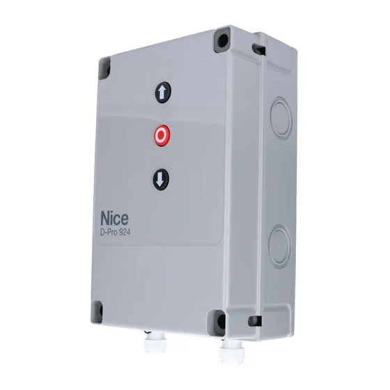
5.1.3; in this case, at least one pair of photocells must be installed as shown in Fig. 2. PRODUCT DESCRIPTION AND INTENDED USE DPRO924 is a control unit to be used to automate sectional balanced doors. It can control motors with an encoder or Hall effect position control system or using electromechanical limit switches. -
Page 7: Electrical Connections
Input for the connection of the Oview programmer, with the appropriate IBT4N adapter. CAUTION! - Disconnect the power before connecting/disconnecting the programmer. Input for the connection of the radio receiver aerial (note: in Nice flashers Mod. ELDC, the aerial is built-in) Aerial STOP Input for the connection of resistive-type sensitive edges (8k2) or optical ones (OSE), as described below (fig. -
Page 8: Control Unit Electrical Connections
For more information, please contact the Nice Customer Service. 3.2 - Collegamenti elettrici della centrale di comando (fig. 5) CAUTION! –... -
Page 9: Connecting A Radio Receiver
TABLE 2 Command No. 3 Open Command No. 4 Close SMXI, SMXIS Receiver in “Mode 1 or 2” Command No. 5 Stop output description Command No. 6 Step-by-Step Condominium Output No. 1 Step-by-Step Command No. 7 Step-by-Step High priority Output No. 2 Partial open;... -
Page 10: Programming
3 seconds) Important - Unlocking with Nice SUMO motor: when the SUMO mo- tor is unlocked, if the DPRO924 control unit is on, it stores the command. To synchronize the encoder position again, closing as far as the maximum closing position must be performed. -
Page 11: Operating Modes
‘hold-to-run’ mode, until synchronization of the encoder position is completed. 4.5 - Operating modes To perform this procedure, follow the following instructions: CAUTION! - If the functions of Table 3 are programmed with the Oview programming unit, it is necessary to set the dip switches to OFF. Select the type of motor, setting dip switches B-2 and B-3 to OFF TABLE 3: DIP SWITCH A... -
Page 12: Modifying The Speed Value
4.5.3 - Modifying the speed value Set dip switch 2-B to OFF = It is possible to modify the opening, opening slowdown, closing and closing the OK led flashes regularly with slowdown speed using the Oview accessory or the board keys. green light. -
Page 13: Further Details
FURTHER DETAILS 6.1 - Connecting photocells and accessories in standby mode The “Total stand by” function is used to reduce consumption and is useful when there is a buffer battery because it allows prolonging the battery charge, it can be activated using the Oview programmer. Once the “Stand by Time”... -
Page 14: Connecting A Buffer Battery
6.3 - Connecting a buffer battery The control unit is prepared for the installation of the buffer bat- tery mod. PS224 (optional accessory): 7.2 Ah with built-in battery charger. To connect the buffer battery, proceed as shown on the side. CAUTION! - The electrical connection of the buffer battery to the control unit must be done only after completing all the installation and programming phases, since the battery is an... -
Page 15: Product Disposal
7.2 - Diagnostics Some devices are supposed to issue warnings that allow identifying their status or any faults. Table 6 describes the various messages with their relative causes and solutions; the warnings are based on combinations of colours, OK led flashing and a possible, suitably programmed, flasher connected to the outputs of the control unit. -
Page 16: Ce Declaration Of Conformity
TECHNICAL SPECIFICATIONS OF THE PRODUCT WARNINGS: • All technical specifications stated herein refer to an ambient temperature of 20° C (± 5° C). • Nice S.p.A. reserves the right to apply modifications to products at any time when deemed necessary, maintaining the same intended use and functionality. - Page 17 “partly completed machinery” Note: the contents of this declaration correspond to that stated in the official document filed in the offices of Nice S.p.A. and, in particular, the latest version thereof available prior to the printing of this manual. The text herein has been re-edited for editorial purposes. A copy of the original declaration can be requested from Nice S.p.A.
- Page 18 Nice SpA Via Callalta, 1 31046 Oderzo (TV) Italy www.niceforyou.com info@niceforyou.com...
Need help?
Do you have a question about the DPRO924 and is the answer not in the manual?
Questions and answers