Advertisement
Quick Links
Advertisement

Related Manuals for ABL SBC Home


Summary of Contents for ABL SBC Home
- Page 1 SBC Home Installation manual...
- Page 2 20 pages English www.abl.de...
- Page 3 Charge controller address vs. current sensor input Installation examples TN network Installation examples IT network Installation in TT network Configuring home Failure handling Limited operation mode Status indicator Control input 1 and 2 Relay output Technical specification Contact information English www.abl.de...
- Page 4 "not in accordance with the intended purpose". is not liable for any damage or inadequate/incorrect outcomes resulting from improper configuration or use. 2. Terms 1. Charging station 3. Charging pole 5. Charge controller (EVCC) 2. Wallbox 4. Charge point English www.abl.de...
- Page 5 • 230V AC and 400V AC TN-S, star topology, with 120 degrees between each phase, hereafter called TN network • 230V AC IT delta topology, with 120 degrees between each phase (Norway only), hereafter called IT network home is only compatible with charge controllers from ABL SURSUM GmbH, Germany. English www.abl.de...
- Page 6 • Maximum 5 charge points for three-phase charging for IT network with local TN network via a 25kVA transformer • Compliant with charge controllers from ABL with firmware 2.7C/CD, 2.8C/CD or newer • Use Mode-3 cable only. Mode changing adaptors between charge point and vehicle are not allowed according to international standardization •...
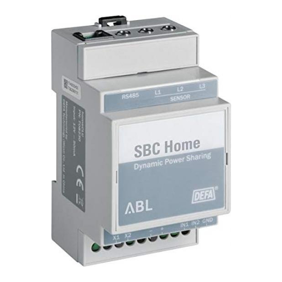
- Page 7 Input AC current sensor 1 Input AC current sensor 2 Communication port Input AC current sensor 3 Relay output Control input ground LED status indicator Control input 2 12V DC power (−) Control input 1 12V DC power (+) LED power indicator English www.abl.de...
- Page 8 This is important for single-phase charging, and for three-phase charging in cases where single-phase vehicles are connected. PE-wiring is intentionally not shown in any of the installation diagrams. English www.abl.de...
- Page 9 All phases may be distributed with a regular "L1-L2-L3-N" bus bar suitable for 4-pole DIN L1 L2 L3 N L1 L2 L3 N L1 L2 L3 N block devices. English www.abl.de...
- Page 10 The example below shows how a CAT5 cable with solid copper core wires may be connected. Make sure the mid pair of terminals are connected to a twisted pair. RJ12 RJ12 Pin 1 Pin 2 M (GND) Pin 3 A (Data) Pin 4 B (Data) Pin 5 M (GND) Pin 6 English www.abl.de...
- Page 11 Some electric vehicles have an onboard charging system that requires a TN network to function. Use a transformer in an IT network to create a local TN network to charge these vehicles. The type and the dimension of the transformer is not specified in this document. Only the principle is shown. English www.abl.de...
- Page 12 10. Configuring the wallbox for home • Open the wallbox and connect the "USB-RS485 interface" (adjustment kit) from ABL to the charge controller. • With the PC application, set the maximum charging current planned in section titled "6. Before installation".
- Page 13 › Warning! Be sure to clip the AC current sensor(s) on to the phase(s) that correspond(s) to the chosen connection pattern for the charging station(s). See the installation diagram for your installation in a separate document. Preferred Optional English www.abl.de...
- Page 14 Do not route the SBC home cables in parallel with the supply lines. Secure the cables with nylon cable ties to suitable fixing points. • Power up SBC home by connecting 230V AC to the power supply. › Warning! Check connections before...
- Page 15 12. Charge controller address vs. current sensor input SBC home Power line in/ Charge controller charging network address AC current sensor input Single-phase TN network/ single-phase charging Three-phase TN network/ single-phase charging S1 + S2 + S3 S1 + S2 + S3...
- Page 16 Single Single Three Single See "SBC home Single Single-phase Single installation diagrams for IT Three Single-phase Single network". Three Three-phase Single Three Three-phase Three 15. Installation in TT network For TT network, with or without neutral: contact ABL. English www.abl.de...
- Page 17 16. Configuring SBC home Instructions for downloading the software to configure SBC home are described on a separate sheet in the SBC home package. Note! Configure according to the "power line in" network. • Connect a Windows computer or an Android device to the 12VDC SBC home's communication port.
- Page 18 SBC home automatically detects current sensor failure and loss of communication with the charge point(s). In the case of current sensor failure, SBC home will go into limited operation mode. In the case of communication loss, SBC home will continue trying to establish communication for 30 seconds.
- Page 19 • Always off (default) Relay Load • On when charging › Shorting terminals X1 and X2 • Off when charging › Opening terminals X1 and X2 • On when error Load › Shorting terminals X1 and X2 (e.g. lamp) English www.abl.de...
- Page 20 Dimensions homeCLU (W x H x D): 54 x 91 x 58mm DIN rail modules, homeCLU: 3 modules DIN rail modules, power supply: 1.5 modules Weight, homeCLU: Weight, power supply: Protection class homeCLU and power supply Class II Recycling: www.abl.de English...
Need help?
Do you have a question about the SBC Home and is the answer not in the manual?
Questions and answers