Table of Contents
Advertisement
UM1956
User manual
STM32 Nucleo-32 boards
Introduction
The STM32 Nucleo-32 boards (NUCLEO-F031K6, NUCLEO-F042K6, NUCLEO-F303K8,
NUCLEO-L011K4, NUCLEO-L031K6, NUCLEO-L412KB, NUCLEO-L432KC) provide an
affordable and flexible way for users to try out new concepts and build prototypes with
STM32 microcontrollers, choosing from the various combinations of performance, power
™
consumption and features. The Arduino
Nano connectivity support makes it easy to
expand the functionality of the Nucleo-32 open development platform with a wide choice of
specialized shields. The STM32 Nucleo-32 boards do not require any separate probe as
they integrate the ST-LINK/V2-1 debugger/programmer and come with the STM32
comprehensive software HAL library, together with various packaged software examples, as
®
™
well as direct access to the Arm
Mbed
online resources at http://mbed.org.
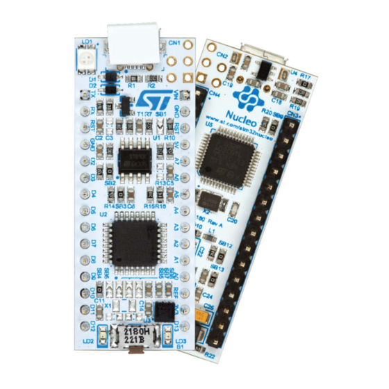
Figure 1. STM32 Nucleo-32 board
Picture not contractual.
August 2018
UM1956 Rev 4
1/35
www.st.com
1
Arrow.com.
Downloaded from
Advertisement
Table of Contents

Related Manuals for ST NUCLEO-F031K6


Summary of Contents for ST NUCLEO-F031K6
-
Page 1: Figure 1. Stm32 Nucleo-32 Board
Nucleo-32 open development platform with a wide choice of specialized shields. The STM32 Nucleo-32 boards do not require any separate probe as they integrate the ST-LINK/V2-1 debugger/programmer and come with the STM32 comprehensive software HAL library, together with various packaged software examples, as ®... -
Page 2: Table Of Contents
Embedded ST-LINK/V2-1 ........14... - Page 3 UM1956 Contents Appendix A Compliance statements........33 Federal Communications Commission (FCC) and Industry Canada (IC) Compliance Statements .
- Page 4 Table 9. Arduino Nano connectors on NUCLEO-F031K6 ....... . 21 Table 10.
- Page 5 USB composite device ........... . 14 Figure 7. NUCLEO-F031K6, NUCLEO-F042K6, NUCLEO-F303K8 pin assignment ... . 29 Figure 8.
-
Page 6: Features
• Flexible board power supply options: – ST-LINK USB V – External source • On-board ST-LINK/V2-1 debugger/programmer with USB re-enumeration capability: mass storage, Virtual COM port, debug port • Support of a wide choice of Integrated Development Environments (IDEs) including ™ ®... -
Page 7: Product Marking
• On the targeted STM32 that is soldered on the board (for illustration of STM32 marking, refer to the section Package information of the STM32 datasheet at www.st.com). • Next to the evaluation tool ordering part number, that is stuck or silk-screen printed on the board. -
Page 8: Conventions
Conventions UM1956 Table 2. Codification explanation (continued) NUCLEO-TXXXKY Description Example: NUCLEO-L412KB STM32 package pin count 32 pins STM32 Flash memory size: – 4 for 16 Kbytes – 6 for 32 Kbytes 128 Kbytes – 8 for 64 Kbytes – B for 128 Kbytes –... -
Page 9: Quick Start
• The demonstration software and several software examples on how to use the STM32 Nucleo-32 board features, are available at the www.st.com/stm32nucleo webpage. • Develop an application using the available examples. System requirements ®... -
Page 10: Hardware Layout And Configuration
The STM32 Nucleo-32 board is based on a 32-pin STM32 microcontroller in LQFP or UFQFPN package. Figure 2 illustrates the connections between the STM32 and its peripherals (ST-LINK/V2-1, push-button, LED, and Arduino Nano connectors). Figure 3: STM32 Nucleo-32 board top layout... -
Page 11: Stm32 Nucleo-32 Board Layout
STM32 Nucleo-32 board top layout ST-LINK Micro B USB connector (Red/Green LED) ST-LINK SWD connector (reserved) Connect VCP TX to ST-LINK Power configuration Connect VCP RX to ST-LINK Connect PF1/PC15 to D7 Connect PF1/PC15 to X1 Connect PF0/PC14 to X1 Connect PF0/PC14 to D8... -
Page 12: Figure 4. Stm32 Nucleo-32 Board Bottom Layout
Hardware layout and configuration UM1956 Figure 4. STM32 Nucleo-32 board bottom layout ST-LINK RESET Arduino Nano connector SB18 Connect D4 to A4 Arduino Nano connector SB16 Connect D5 to A5 SB12 SB11 Connect BOOT0 to GND Connect pin 16 to... -
Page 13: Stm32 Nucleo-32 Board Mechanical Drawing
UM1956 Hardware layout and configuration STM32 Nucleo-32 board mechanical drawing Figure 5. STM32 Nucleo-32 board mechanical drawing UM1956 Rev 4 13/35 Arrow.com. Arrow.com. Arrow.com. Arrow.com. Arrow.com. Arrow.com. Arrow.com. Arrow.com. Arrow.com. Arrow.com. Arrow.com. Arrow.com. Arrow.com. Downloaded from Downloaded from Downloaded from Downloaded from Downloaded from Downloaded from... -
Page 14: Embedded St-Link/V2-1
Activating the readout protection on the STM32 target, prevents the target application from running afterwards. The target readout protection must be kept disabled on ST- LINK/V2-1 boards. The embedded ST-LINK/V2-1 is directly connected to the SWD port of the target STM32. 6.3.1 Drivers ®... -
Page 15: St-Link/V2-1 Firmware Upgrade
The ST-LINK/V2-1 embeds a firmware upgrade mechanism for in-situ upgrade through the USB port. As the firmware may evolve during the lifetime of the ST-LINK/V2-1 product (for example new functionalities added, bug fixes, support for new microcontroller families), it is recommended to visit www.st.com... -
Page 16: Power Supply And Power Selection
EN-60950-1: 2006+A11/2009, and must be Safety Extra Low Voltage (SELV) with limited power capability. In case the power supply is +3V3, the ST-LINK is not powered and cannot be used. 6.4.1 Power supply input from USB connector The STM32 Nucleo-32 board and shield board can be powered from the ST-LINK USB connector CN1. -
Page 17: External Power Supply Inputs
SB9 must be off. VIN or +5 V power supply When powered from VIN or +5 V, it is still possible to use ST-LINK for communication for programming or debugging only, but it is mandatory to power the board first, using VIN or +5 V, then to connect the USB cable to the PC. -
Page 18: 3V3 Power Supply
Using the +3V3 (CN4 pin 14) directly as power input, can be interesting, for instance, in case the 3.3 V is provided by a shield board. In this case the ST-LINK is not powered, thus programming and debugging features are not available. When the board is powered by +3V3 (CN4 pin 14), the solder bridge SB14 and SB9 (NRST) must be off. -
Page 19: Jp1 (Idd)
1. In applications where VCP is used for communication at a speed higher than 9600 bauds, it may be needed to use this solder bridge configuration, to use 8 MHz clock (MCO from ST-LINK) and get a more precise frequency. -
Page 20: Usart Virtual Communication
USART virtual communication Thanks to SB2 and SB3, the USART interface of STM32 available on PA2 (TX) and PA15 (RX), can be connected to ST-LINK/V2-1. When USART is not used it is possible to use PA2 as Arduino Nano A7. Refer to Table Table 7. -
Page 21: Arduino Nano Connectors
STM32 on Arduino Nano connectors. Figure 7 Figure 8 show Arduino Nano connectors and pin assignments for NUCLEO-F031K6, NUCLEO-F042K6, NUCLEO-F303K8, NUCLEO-L011K4, NUCLEO- L031K6 and NUCLEO-L432KC. Table 9. Arduino Nano connectors on NUCLEO-F031K6 Connector Pin number Pin name STM32 pin Function... - Page 22 Hardware layout and configuration UM1956 Table 9. Arduino Nano connectors on NUCLEO-F031K6 (continued) Connector Pin number Pin name STM32 pin Function Right connector Power input Ground RESET NRST RESET 5 V input/output ADC_IN2 ADC_IN7 ADC_IN6 || I2C1_SCL ADC_IN5 || I2C1_SDA...
-
Page 23: Table 10. Arduino Nano Connectors On Nucleo-F042K6
UM1956 Hardware layout and configuration Table 10. Arduino Nano connectors on NUCLEO-F042K6 Connector Pin number Pin name STM32 pin Function Left connector USART1_TX PA10 USART1_RX RESET NRST RESET Ground PA12 TIM3_CH3 TIM16_CH1N TIM14_CH1 TIM1_CH1 PA11 SPI_CS || TIM1_CH4 SPI1_MOSI || TIM3_CH2 SPI1_MISO Right connector Power input... -
Page 24: Table 11. Arduino Nano Connectors On Nucleo-F303K8
Hardware layout and configuration UM1956 Table 11. Arduino Nano connectors on NUCLEO-F303K8 Connector Pin number Pin name STM32 pin Function Left connector USART1_TX PA10 USART1_RX RESET NRST RESET Ground PA12 TIM3_CH3 TIM16_CH1N TIM3_CH4 TIM1_CH1 PA11 SPI_CS || TIM1_CH4 SPI1_MOSI || TIM17_CH1 SPI1_MISO Right connector Power input... -
Page 25: Table 12. Arduino Nano Connectors On Nucleo-L011K4
UM1956 Hardware layout and configuration Table 12. Arduino Nano connectors on NUCLEO-L011K4 Connector Pin Name STM32 pin Function number Left connector USART2_TX PA10 USART2_RX RESET NRST RESET Ground PA12 TIM2_CH3 TIM2_CH3 TIM2_CH4 PC14 PC15 PA11 SPI_CS || TIM SPI1_MOSI || TIM SPI1_MISO Right connector Power input... -
Page 26: Table 13. Arduino Nano Connectors On Nucleo-L031K6
Hardware layout and configuration UM1956 Table 13. Arduino Nano connectors on NUCLEO-L031K6 Connector Pin number Pin name STM32 pin Function Left connector USART2_TX PA10 USART2_RX RESET NRST RESET Ground PA12 TIM2_CH3 TIM21_CH1 TIM2_CH4 PC14 PC15 TIM2_CH1 PA11 SPI_CS || TIM21_CH2 SPI1_MOSI || TIM22_CH2 SPI1_MISO Right connector... -
Page 27: Table 14. Arduino Nano Connectors On Nucleo-L412Kb
UM1956 Hardware layout and configuration Table 14. Arduino Nano connectors on NUCLEO-L412KB Connector Pin number Pin name STM32 pin Function Left connector USART1_TX PA10 USART1_RX RESET NRST RESET Ground PA12 TIM1_CH2N TIM16_CH1N TIM1_CH3N PC14 PC15 TIM1_CH1 PA11 SPI_CS || TIM1_CH4 SPI1_MOSI || TIM SPI1_MISO Right connector... -
Page 28: Table 15. Arduino Nano Connectors On Nucleo-L432Kc
Hardware layout and configuration UM1956 Table 15. Arduino Nano connectors on NUCLEO-L432KC Connector Pin number Pin name STM32 pin Function Left connector USART1_TX PA10 USART1_RX RESET NRST RESET Ground PA12 TIM1_CH2N TIM16_CH1N TIM1_CH3N PC14 PC15 TIM1_CH1 PA11 SPI_CS || TIM1_CH4 SPI1_MOSI || TIM SPI1_MISO Right connector... -
Page 29: Figure 7. Nucleo-F031K6, Nucleo-F042K6, Nucleo-F303K8 Pin Assignment
UM1956 Hardware layout and configuration Figure 7. NUCLEO-F031K6, NUCLEO-F042K6, NUCLEO-F303K8 pin assignment Figure 8. NUCLEO-L011K4, NUCLEO-L031K6, NUCLEO-L412KB and NUCLEO-L432KC pin assignment UM1956 Rev 4 29/35 Arrow.com. Arrow.com. Arrow.com. Arrow.com. Arrow.com. Arrow.com. Arrow.com. Arrow.com. Arrow.com. Arrow.com. Arrow.com. Arrow.com. Arrow.com. Arrow.com. Arrow.com. -
Page 30: Electrical Schematics
Electrical schematics UM1956 30/35 UM1956 Rev 4 Arrow.com. Arrow.com. Arrow.com. Arrow.com. Arrow.com. Arrow.com. Arrow.com. Arrow.com. Arrow.com. Arrow.com. Arrow.com. Arrow.com. Arrow.com. Arrow.com. Arrow.com. Arrow.com. Arrow.com. Arrow.com. Arrow.com. Arrow.com. Arrow.com. Arrow.com. Arrow.com. Arrow.com. Arrow.com. Arrow.com. Arrow.com. Arrow.com. Arrow.com. Arrow.com. Downloaded from Downloaded from Downloaded from Downloaded from Downloaded from... -
Page 31: Figure 10. Mcu
UM1956 Electrical schematics Arduino Connector UM1956 Rev 4 31/35 Arrow.com. Arrow.com. Arrow.com. Arrow.com. Arrow.com. Arrow.com. Arrow.com. Arrow.com. Arrow.com. Arrow.com. Arrow.com. Arrow.com. Arrow.com. Arrow.com. Arrow.com. Arrow.com. Arrow.com. Arrow.com. Arrow.com. Arrow.com. Arrow.com. Arrow.com. Arrow.com. Arrow.com. Arrow.com. Arrow.com. Arrow.com. Arrow.com. Arrow.com. Arrow.com. Arrow.com. Downloaded from Downloaded from Downloaded from... -
Page 32: Figure 11. St-Link/V2-1
Electrical schematics UM1956 32/35 UM1956 Rev 4 Arrow.com. Arrow.com. Arrow.com. Arrow.com. Arrow.com. Arrow.com. Arrow.com. Arrow.com. Arrow.com. Arrow.com. Arrow.com. Arrow.com. Arrow.com. Arrow.com. Arrow.com. Arrow.com. Arrow.com. Arrow.com. Arrow.com. Arrow.com. Arrow.com. Arrow.com. Arrow.com. Arrow.com. Arrow.com. Arrow.com. Arrow.com. Arrow.com. Arrow.com. Arrow.com. Arrow.com. Arrow.com. Downloaded from Downloaded from Downloaded from Downloaded from... - Page 33 UM1956 Compliance statements Appendix A Compliance statements Federal Communications Commission (FCC) and Industry Canada (IC) Compliance Statements A.1.1 FCC Compliance Statement Part 15.1934 This device complies with Part 15 of the FCC Rules. Operation is subject to the following two conditions: (1) this device may not cause harmful interference, and (2) this device must accept any interference received, including interference that may cause undesired operation.
-
Page 34: Table 16. Document Revision History
Revision history UM1956 Revision history Table 16. Document revision history Date Revision Revision Details 14-Oct-2015 Initial version. Update to introduce NUCLEO-L011K4. Updated Introduction, Chapter 1: Features, Chapter 3: Ordering information, 21-Mar-2016 Chapter 6: Hardware layout and configuration. Added Appendix A: Compliance statements. - Page 35 ST products and/or to this document at any time without notice. Purchasers should obtain the latest relevant information on ST products before placing orders. ST products are sold pursuant to ST’s terms and conditions of sale in place at the time of order acknowledgement.
Need help?
Do you have a question about the NUCLEO-F031K6 and is the answer not in the manual?
Questions and answers