
Related Manuals for Ultraflex ZTF Tiller System


Summary of Contents for Ultraflex ZTF Tiller System
- Page 1 Installation manual TILLER SYSTEM page 2 pag. 29 PARTNER (Dr./Dis./Des. n° 35010/a - 19/04/2019)
- Page 2 Dear Customer, The ZTF Tiller Systems are produced by ULTRAFLEX Company belonging to ULTRAFLEX GROUP. ULTRAFLEX GROUP is a leader in steering systems for pleasure and professional boats for more than 85 years. ULTRAFLEX production is since ever synonimous of reliability and safety. All ULTRAFLEX products are...
-
Page 3: Table Of Contents
ULTRAFLEX Installation manual TABLE OF CONTENTS DOCUMENT REVISIONS............................4 MANUAL USE AND SYMBOLS USED ..........................5 INTRODUCTION LETTER..............................6 WARRANTY ..................................6 SECTION 1 - PRODUCT DESCRIPTION 1.1 ZTF SYSTEM DESCRIPTION ............................ 7 1.2 OPERATING PRINCIPLE ............................8 SECTION 2 - TRANSPORT 2.1 GENERAL WARNINGS .............................. -
Page 4: Document Revisions
ULTRAFLEX Installation manual DOCUMENT REVISIONS Rev. Date Revision description 25/01/2019 First edition page 4 of 55 - ZTF SYSTEM... -
Page 5: Manual Use And Symbols Used
ULTRAFLEX Installation manual MANUAL USE AND SYMBOLS USED THE INSTALLATION AND MAINTENANCE MANUAL should be kept for regular reference by the owner of the boat and transfered to any new owner with the boat. It is necessary to read carefully the manual, before ANY ACTIVITY involving the product, handling and unloading included. -
Page 6: Introduction Letter
ULTRAFLEX declines all responsibility for possible mistakes in this manual due to printing errors. Although the main features of the type of product described are not subject to change, ULTRAFLEX Company reserves the right to modify any parts, details and accessories it deems necessary to improve the product or for manufacturing or commercial requirements, at any time and without being obliged to update this manual immediately. -
Page 7: Ztf System Description
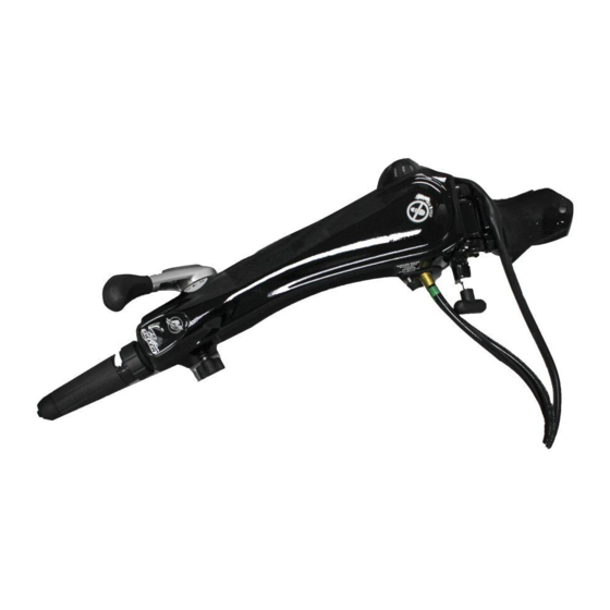
1.1 ZTF Tiller System description The ZTF Tiller System is a hydraulic device that neutralizes the propeller torque of outboard engines on the tiller handle while the operator is not actively making a steering course change. It enables the operator to maintain the right course without excessive physical effort. -
Page 8: Operating Principle
If the engine moves, tighten the By-Pass Knob in the clockwise direction and check again to see if the engine moves. If it continues to move, do not use the boat and contact your dealer of ULTRAFLEX for technical support. -
Page 9: General Warnings
In case of damage, do not use the ZTF Tiller System and notify the freight carrier and your dealer/distributor immediately. The ZTF Tiller System is provided with the following items: Main device ®... - Page 10 ULTRAFLEX Installation manual KIT QU1 KIT ND1 CAUTION The packaging must be disposed of according to the existing laws. page 10 of 55 - ZTF SYSTEM...
-
Page 11: Safety Warnings
- DO NOT PUT HANDS BETWEEN THE MOVING PARTS. - Do not disable in any way the safety devices. - Do not modify or add devices to the system, without ULTRAFLEX written authorization or technical intervention which will prove the modification. -
Page 12: Installation With 150-175-200 Hp Yamaha
ULTRAFLEX Installation manual 3.3 Installation with 150-175-200 HP Yamaha ® engines As reported on the previous pages, the ZTF installation K I T with 150-175-200 HP engines requires the use of KIT QU1 (see also par. 2.2). NECESSARY TOOLS Open end... - Page 13 ULTRAFLEX Installation manual Place the two ultrabolts (6) and (7) with washers (8) into the engine arm (9) up to half of their length. NOTICE The screws must protrude from the engine arm by around 15 mm. Assemble the device with bracket (1) on the engine arm (9).
- Page 14 ULTRAFLEX Installation manual Place the cylinder link arm (12) on the rear screw (7). NOTICE In order to complete the faste- ning process of the cylinder to the engine hose, refer to the instructions contained in the manual of the cylinder.
- Page 15 ULTRAFLEX Installation manual Bring the two ultrabolts into contact with the engine tiller arm and fasten them using a 9/16" wrench with a torque of 54 Nm (40 lb.- ft.). CAUTION This operation requires careful attention. Afterwards, while holding a screw with a 9/16"...
-
Page 16: Installation With 90-115-130 Hp Yamaha
ULTRAFLEX Installation manual 3.4 Installation with 90-115-130 HP Yamaha ® engines from 2015 to date As reported on the previous pages, the ZTF installation KIT ND1 with 90-115-130 HP engines from 2015 requires the use of KIT ND1 (see also par. 2.2). - Page 17 ULTRAFLEX Installation manual Fasten the device with the bracket on the engine arm using nuts (X) and interposing washers (Y), ® following the tightening torque and the instructions contained in the manual of Yamaha tiller handle Apply grease to the pivots before tightening the nuts.
-
Page 18: Tiller Handle Assembly
ULTRAFLEX Installation manual 3.5 Yamaha ® tiller handle assembly ® The Yamaha tiller handle is composed of the main body (1) and the original bracket (2) for connecting it to the engine arm. In order to install the tiller handle on the ZTF device, it is necessary to remove bracket (2) and assemble the main body (1) directly on the ZTF device. - Page 19 ULTRAFLEX Installation manual 3.5.2 ZTF device assembly on tiller handle The main body of the tiller handle must be fastened to the device in line with the fork. Fasten the tiller handle (1) to device (2), taking care of positioning...
-
Page 20: Tiller Handle Disassembly From Outboard Engine ("Refitting" Installation)
ULTRAFLEX Installation manual 3.6 Tiller handle disassembly from outboard engine ("refitting" installation) Remove the tiller handle from the engine arm, taking care of keeping the extracted nuts and washers. Check their conditions together with the ring preventing the nut lock. -
Page 21: Ordinary Maintenance
This kind of events entails oil leakage from the system and, consequently, refilling is required. Fault situations must be examined on case-by-case basis. The purging procedure of the ZTF system requires the use of Ultraflex Bubble Buster, which is not provided in this kit. NECESSARY TOOLS... - Page 22 Installation manual NOTICE In order to proceed with the system filling and purging, a hydraulic oil (Ultraflex OL150 or compatible ones) is recommended, as indicated in the use and maintenance manual of UC130 cylinder. Before connecting the Bubble Buster to the system, read its manual in order to identify its related parts.
- Page 23 ULTRAFLEX Installation manual 3. Connect the pair of transparent hoses to the Bubble Buster fitting. Such hoses are provided with a small and a big quick coupling at their end, Small 4. Connect the other pair of transparent hoses to the cylinder purge valves. Such hoses have the same...
- Page 24 ULTRAFLEX Installation manual 5. Loosen the release nuts (3) for enabling the oil to pass through. Do not unscrew more than one turn and a half. Use a 16 mm wrench. Connect the battery clamps: the red clip to the positive terminal and the black one to the negative terminal.
- Page 25 ULTRAFLEX Installation manual 5. Move the cylinder slowly towards the opposite side (port, see picture 2), by always acting on the tiller handle. 6. Once on the port side, leave the cylinder in this position and wait again for a few minutes.
- Page 26 ULTRAFLEX Installation manual 5 DISMANTLING 5.1 Dismantling When for any reason, the ZTF system is put out of service, it is necessary to follow some rules in order to respect the environment. Sheaths, pipelines, plastic or non-metallic components must be disassembled and disposed of separately.
- Page 27 ULTRAFLEX Installation manual NOTES page 27 of 55 ZTF SYSTEM...
- Page 28 ULTRAFLEX Installation manual NOTES page 28 of 55 - ZTF SYSTEM...
- Page 29 Manuale di installazione SISTEMA (ZERO TORQUE FEEDBACK) PARTNER...
- Page 30 Gentile Cliente, I sistemi ZTF sono prodotti da ULTRAFLEX società del GRUPPO ULTRAFLEX. Il GRUPPO ULTRAFLEX è da più di 85 anni un punto di riferimento nella costruzione di accessori per la nautica da diporto e professionale. Da sempre la nostra produzione é sinonimo di grande affidabilità e sicurezza. Tutta la produzione ULTRAFLEX é...
- Page 31 ULTRAFLEX Manuale di installazione INDICE GENERALE INDICE DELLE REVISIONI DEL DOCUMENTO.....................32 USO DEL MANUALE E SIMBOLOGIA IMPIEGATA.....................33 LETTERA INFORMATIVA..........................34 GARANZIA..............................34 SEZIONE 1 - DESCRIZIONE DEL PRODOTTO 1.1 DESCRIZIONE DEL SISTEMA ZTF......................35 1.2 PRINCIPIO DI FUNZIONAMENTO......................36 SEZIONE 2 - TRASPORTO 2.1 AVVERTENZE GENERALI.........................37 2.2 CONTENUTO DEGLI IMBALLI........................38...
- Page 32 ULTRAFLEX Manuale di installazione INDICE DELLE REVISIONI DEL DOCUMENTO Rev. Data Descrizione della revisione 25/01/2019 Prima realizzazione pag. 32 di 55 - SISTEMA ZTF...
- Page 33 ULTRAFLEX Manuale di installazione USO DEL MANUALE E SIMBOLOGIA IMPIEGATA Il MANUALE DI INSTALLAZIONE E MANUTENZIONE è il documento che accompagna il prodotto dal momento della sua vendita fino alla sua sostituzione e smaltimento. Risulta cioè essere parte integrante del prodotto.
- Page 34 TUTTI I DIRITTI SONO RISERVATI. I diritti di pubblicazione, i marchi, le sigle e le fotografie dei prodotti ULTRAFLEX presenti in questo manuale sono di proprietà della ULTRAFLEX che ne vieta qualsiasi riproduzione anche par- ziale.
- Page 35 Non utilizzare l'apparecchiatura per uno scopo diverso da quello per cui è stata destinata, specificato nel manuale di installazione. ATTENZIONE ® Per installazioni diverse dai modelli di motori Yamaha sopra citati, contattare il Servizio di Assistenza Tecnica Ultraflex. pag. 35 di 55 SISTEMA ZTF...
- Page 36 Se il motore invece si muove, ruotare la manopola del by-pass in senso orario e verificare l'eventuale persistere del movimento da parte del motore. Se ciò avvenisse, non usare la barca e contattare il vostro rivenditore Ultraflex per ricevere assistenza tecnica. pag. 36...
- Page 37 ULTRAFLEX Manuale di installazione 2 TRASPORTO 2.1 Avvertenze generali Il peso del prodotto compreso l'imballo è inferiore a 20 Kg (44 lbs.), pertanto la sua movimentazione può essere effettuata manualmente. AVVERTENZA Il personale addetto alla manipolazione del carico deve operare con guanti protettivi e scarpe anti infortunistiche.
- Page 38 ULTRAFLEX Manuale di installazione KIT QU1 KIT ND1 AVVERTENZA Gli imballi devono essere smaltiti secondo le direttive vigenti. pag. 38 di 55 - SISTEMA ZTF...
- Page 39 RISPETTATE TASSATIVAMENTE le precauzioni ed i criteri di sicurezza indicati nel manuale. La non osservanza potrebbe comportare la perdita di rotta con possibili danni, lesioni e morte. ULTRAFLEX declina ogni responsabilità in caso di errori in fase di installazione, uso scorretto, negligenza o mancanza di manutenzione ordinaria o controlli.
- Page 40 ULTRAFLEX Manuale di installazione 3.3 Installazione con motori Yamaha ® 150-175-200 CV Come indicato in precedenza, per l'installazione del K I T sistema ZTF con motore da 150-175-200 CV, è necessario utilizzare il KIT QU1 (vedi anche par. 2.2). UTENSILI NECESSARI...
- Page 41 ULTRAFLEX Manuale di installazione Posizionare i due bulloni ultrabolt (6) e (7) completi di rondelle (8) sul braccetto motore (9) per circa metà della loro lunghezza. NOTA Le viti devono sporgere dal braccetto motore di circa 15 mm. Montare dispositivo completo di staffa (1) sul braccetto motore (9).
- Page 42 ULTRAFLEX Manuale di installazione Posizionare il braccetto del cilindro (12) sulla vite posteriore (7). NOTA Per completare il fissaggio del cilindro al tubo motore, fare riferimento alle istruzioni contenute nel manuale cilindro. Avvitare l'ultrabolt (7) in modo che sporga dal braccetto cilindro...
- Page 43 ULTRAFLEX Manuale di installazione Portare i due ultrabolt in battuta sul braccetto motore e serrarli con una chiave da 9/16" con una coppia di 54 Nm (40 lb.-ft.). ATTENZIONE É obbligatorio eseguire questa operazione con estrema attenzione. uccessivamente, tenendo ferma una vite con una chiave da 9/16", serrare il dado...
- Page 44 ULTRAFLEX Manuale di installazione 3.4 Installazione con motori Yamaha ® 90-115-130 CV dal 2015 ad oggi Come indicato in precedenza, per l'installazione del KIT ND1 sistema ZTF con motore da 90-115-130 CV dopo 2015, è necessario utilizzare il KIT ND1 (vedi anche par. 2.2).
- Page 45 ULTRAFLEX Manuale di installazione Fissare il dispositivo completo di staffa al braccetto motore tramite i dadi (X) interponendo le rotelle ® (Y), rispettando la coppia di serraggio e le istruzioni riportate nel manuale del tiller handle Yamaha Applicare del grasso sui perni prima di avvitare i dadi.
- Page 46 ULTRAFLEX Manuale di installazione 3.5 Montaggio del tiller handle Yamaha ® ® Il tiller handle Yamaha è composto dal corpo principale (1) e dalla staffa originale (2) per connessione al braccetto motore. Per poter installare il tiller handle sul dispositivo ZTF, occorre rimuovere la staffa (2) e montare direttamente il corpo principale (1) sul dispositivo ZTF.
- Page 47 ULTRAFLEX Manuale di installazione 3.5.2 Montaggio dispositivo ZTF sul tiller handle Il corpo principale del tiller handle va fissato al dispositivo in corrispondenza della forcella. Fissare il tiller handle (1) al dispositivo (2) avendo cura di posizionare boccole, distanziali e...
- Page 48 ULTRAFLEX Manuale di installazione 3.6 Smontaggio tiller handle dal motore fuoribordo (installazione di tipo "refitting") Disinstallare il tiller handle dal braccetto motore, avendo cura di conservare i dadi e le rondelle rimosse. Verificarne l'integrità e controllare l'anello antibloccaggio dadi. Sostituire i pezzi anche se...
- Page 49 Le situazioni di guasto devono essere esaminate caso per caso. La procedura di spurgo del sistema ZTF prevede l'uso del Bubble Buster Ultraflex, non fornito in questo kit.
- Page 50 Manuale di installazione NOTA Per procedere al riempimento e spurgo del sistema è necessario utilizzare un olio idraulico (Ultraflex OL150 o compatibili) indicato nel manuale d’uso e manutenzione del cilindro UC130. Prima di collegare il Bubble Buster al sistema, leggere il suo manuale d’uso per identificare le parti che lo compongono.
- Page 51 ULTRAFLEX Manuale di installazione 3. Collegare al raccordo del Bubble Buster la coppia di tubi trasparenti dotata all’estremità di attacchi rapidi, uno piccolo e uno grande. Piccolo Grande 4. Collegare agli spurghi del cilindro l’altra coppia di tubi trasparenti (della stessa dimensione) dotata all’estremità...
- Page 52 ULTRAFLEX Manuale di installazione 5. Allentare i dadi (3) degli sfiati per consentire il passaggio dell’olio. Non svitare oltre un giro e mezzo. Utilizzare una chiave da 16 mm. Collegare le pinze a coccodrillo alla batteria, la pinza rossa al polo positivo, la pinza nera al polo negativo.
- Page 53 ULTRAFLEX Manuale di installazione 5. Muovere lentamente il cilindro fino a portarlo verso il lato opposto (port, vedi figura 2), sempre agendo sulla manopola del tiller handle. 6. Arrivati in fine corsa lato port, lasciare il cilindro in questa posizione e attendere ancora alcuni minuti.
- Page 54 ULTRAFLEX Manuale di installazione 5 SMANTELLAMENTO 5.1 Smantellamento Qualora si intenda, per qualsiasi motivo, mettere fuori servizio il sistema ZTF, è necessario osservare alcune regole fondamentali atte a salvaguardare l’ambiente. Guaine, condotti flessibili, componenti di materiale plastico o comunque non metallico, dovranno essere smontati e smaltiti separatamente.
- Page 55 ULTRAFLEX Manuale di installazione NOTE pag. 55 di 55 SISTEMA ZTF...
- Page 56 ULTRAFLEX S.p.A. 16015 Casella (Genova) Italia - Via Crose, 2...
Need help?
Do you have a question about the ZTF Tiller System and is the answer not in the manual?
Questions and answers