Grundfos DP 10.50 Original Installation And Operating Instructions
Hide thumbs
Also See for DP 10.50:
- Original installation and operating instructions (20 pages) ,
- Manual (11 pages) ,
- Installation and operating instructions manual (80 pages)
Table of Contents
Advertisement
Quick Links
Original installation and operating instructions.
CONTENTS
1.
2.
2.1
2.2
2.3
3.
3.1
3.2
4.
4.1
4.2
5.
5.1
5.2
6.
6.1
7.
7.1
7.2
8.
8.1
8.2
8.3
8.4
8.5
9.
9.1
9.2
9.3
10.
11.
12.
13.
Warning
Prior to installation, read these
installation and operating instructions.
Installation and operation must comply
with local regulations and accepted
codes of good practice.
8
Warning
The use of this product requires
experience with and knowledge of the
Page
product.
Persons with reduced physical,
8
sensory or mental capabilities must not
9
use this product, unless they are under
9
supervision or have been instructed in
9
the use of the product by a person
10
responsible for their safety.
10
Children must not use or play with this
10
product.
10
11
1. Symbols used in this document
11
12
Warning
13
If these safety instructions are not
13
observed, it may result in personal
13
injury!
14
14
Warning
15
If these instructions are not observed,
15
it may lead to electric shock with
16
consequent risk of serious personal
17
injury or death.
18
18
Warning
19
These instructions must be observed
19
for explosion-proof pumps. It is
20
advisable also to follow these
21
instructions for standard pumps.
21
21
If these safety instructions are not
22
observed, it may result in malfunction
Caution
22
or damage to the equipment!
23
23
Notes or instructions that make the job
Note
24
easier and ensure safe operation.
24
25
26
26
27
28
28
Advertisement
Table of Contents

Related Manuals for Grundfos DP 10.50


Summary of Contents for Grundfos DP 10.50
-
Page 1: Table Of Contents
Original installation and operating instructions. Warning The use of this product requires CONTENTS experience with and knowledge of the Page product. Persons with reduced physical, Symbols used in this document sensory or mental capabilities must not General description use this product, unless they are under Product drawings supervision or have been instructed in Applications... -
Page 2: General Description
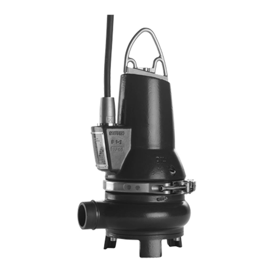
This booklet includes instructions for installation, operation and maintenance of Grundfos DP and EF submersible drainage and effluent pumps with motors of 0.6 to 2.6 kW. Grundfos DP and EF drainage and effluent pumps are portable and designed for pumping domestic and industrial drainage and effluent. -
Page 3: Operating Conditions
After a long period of storage, the pump should be See 9.2 Operating modes. inspected before it is put into operation. Make sure The Grundfos EF pumps are suitable for pumping that the impeller can rotate freely. Pay special effluent and other liquids with solids up to 30 mm. -
Page 4: Identification
4. Identification 4.1 Nameplate The nameplate states the operating data and Fix the additional nameplate supplied with the pump approvals applying to the pump. The nameplate is close to the tank. fixed with rivets to the side of the motor housing close to the cable entry. -
Page 5: Type Key
Please note that not all combination options are available. Code Example DP 10 .50 .15 .EX .2 .1 .5 02 Type range Grundfos drainage pump Grundfos effluent pump Pump passage Maximum solids size [mm] Pump discharge Nominal diameter of pump discharge port [mm]... -
Page 6: Approvals
5. Approvals 5.2 Explanation to the Ex approval The explosion protection classification of the pump is The standard version of DP and EF pumps has been CE 0344 II 2 G Ex d IIB T4 X. tested by VDE, and the explosion-proof version approved by KEMA according to the ATEX directive. -
Page 7: Safety
6. Safety 6.1 Potentially explosive environments Use explosion-proof pumps for applications in Warning potentially explosive environments. Pump installation in tanks must be carried out by specially trained Warning persons. DP and EF pumps must under no Work in or near tanks must be carried circumstance pump combustible out according to local regulations. -
Page 8: Installation
3. Assemble the discharge line in accordance with the generally accepted procedures and without exposing the line to distortion or tension. We recommend to always use Grundfos accessories to avoid malfuncions due 4. Place the guide rails on the auto-coupling base Caution to incorrect installation. -
Page 9: Free-Standing Submerged Installation
8. Slide the guide claw between the guide rails and 7.2 Free-standing submerged installation lower the pump into the tank by means of a chain Pumps for free-standing submerged installation can secured to the lifting bracket of the pump. stand freely on the bottom of the tank or the like. When the pump reaches the auto-coupling base See fig. -
Page 10: Electrical Connection
Grundfos CU 100 control box Do not install Grundfos control boxes, • a Grundfos LC, LCD 107, LC, LCD 108 or pump controllers, Ex barriers and the LC, LCD 110 pump controller. free end of the power cable in potentially explosive environments. -
Page 11: Wiring Diagrams
Float switches used in potentially explosive environments must be approved for this application. They must be connected to the Grundfos DC, DCD or LC, LCD 108 pump controller via an intrinsically safe ˚ ˚ barrier to ensure a safe circuit. -
Page 12: Pump Controllers
Float switches used in potentially explosive environments must be approved for this application. They must be connected to the Grundfos DC, DCD or LC, LCD 108 pump controller via an intrinsically safe barrier to ensure a safe circuit. -
Page 13: Frequency Converter Operation
8.5 Frequency converter operation 8.5.3 Consequences When operating the pump via a frequency converter, For frequency converter operation please observe please be aware of these possible consequences: the following information. • The locked-rotor torque will be lower. How much Requirements must be fulfilled. lower will depend on the frequency converter Recommendations ought to be fulfilled. -
Page 14: Start-Up
9. Start-up 9.2 Operating modes The pumps are designed for intermittent operation Warning (S3). When completely submerged, the pumps can Before starting work on the pump, also operate continuously (S1). make sure that the fuses have been removed or the mains switch has been switched off. -
Page 15: Direction Of Rotation
Except for service on the pump parts, all other service work must be carried Procedure 2: out by Grundfos or a service workshop 1. Let the pump hang from a lifting device, e.g. the authorized by Grundfos. hoist used for lowering the pump into the tank. -
Page 16: Inspection
Replace defective ball bearings. A general overhaul of the pump is usually required in case of defective ball bearings or poor motor function. This work must be carried out by Grundfos or a service workshop authorized by Grundfos. -
Page 17: Cleaning The Pump Housing
If the bush is worn and must be replaced, the 3. Lift the motor part out of the pump housing pump must be checked by Grundfos or a service (pos. 50). As the impeller is fastened to the shaft workshop authorized by Grundfos. -
Page 18: Oil Change
10.5 Oil change After 3000 operating hours or once a year, change the oil in the oil chamber as described below. If the shaft seal has been changed, the oil must be changed as well. See section 10.4 Replacing the shaft seal. -
Page 19: Service Kits
96076171 service for required quantity in oil chamber. 10.7 Contaminated pumps A possible replacement of the cable must be carried out by Grundfos or a Warning Note service workshop authorized by If a pump has been used for a liquid Grundfos. -
Page 20: Fault Finding
11. Fault finding Warning Before attempting to diagnose any fault, make sure that the fuses have been removed or the mains switch has been switched off. It must be ensured that the power supply cannot be accidentally switched on. All rotating parts must have stopped moving. Warning All regulations applying to pumps installed in potentially explosive environments must be observed. -
Page 21: Technical Data
Motor size Winding resistance * Grundfos company or service workshop. Single-phase Starting winding Main winding 0.6 kW 4.5 Ω...
Need help?
Do you have a question about the DP 10.50 and is the answer not in the manual?
Questions and answers