
Related Manuals for Johnson Controls FMS-2000M


Summary of Contents for Johnson Controls FMS-2000M
- Page 1 FMS-2000M Critical Environment Monitor LIT-12013555 Installation Guide July 2023...
- Page 2 Risk of Property Damage. Do not connect the 24 VAC power supply directly to the FMS-2000M display four-position terminal block. You must terminate the power at the remote sensor's nine-position terminal block on the +Vin and -Vin terminals. Failure to follow the wiring instructions may cause permanent damage to the FMS-2000M monitor and void your warranty.
- Page 3 FMS-2000M IMPORTANT: Do not install the FMS-2000M Critical Environment Monitor where the maximum temperature exceeds 125°F (52°C). Installing the device where maximum temperatures exceed 125°F (52°C) may cause damage to the FMS-2000M Critical Environment Monitor and may void the warranty.
- Page 4 Risque de dégâts matériels. Ne pas brancher le bloc d’alimentation de 24 V CA directement au bornier à quatre positions de l’écran du FMS-2000M. Vous devez raccorder l’alimentation aux bornes +Vin et -Vin du bornier à neuf positions du capteur à distance. Ne pas respecter les instructions de câblage peut causer des dommages permanents au moniteur FMS-2000M et annuler votre garantie.
- Page 5 Ne dépassez pas les spécifications électriques du FMS-2000M Critical Environment Monitor. IMPORTANT : N’installez pas le contrôleur d’environnement critique FMS-2000M où la température maximum dépasse 52 °C (125 °F). Installer l’appareil dans un environnement où la température maximum dépasse 52 °C (125 °F) peut endommager FMS-2000M Critical Environment Monitor et peut annuler la garantie.
-
Page 6: Table Of Contents
Location considerations ................................8 Ferrite installation instructions for FMS-2000M series ......................8 Installing the FMS-2000M Thin Mount display for a retrofit application ................9 Installing the FMS-2000M Thin Mount display for a new application ................... 12 Mounting the remote pressure sensor ............................ 14 Wiring the system and BACnet MS/TP communications ...................... -
Page 7: Introduction
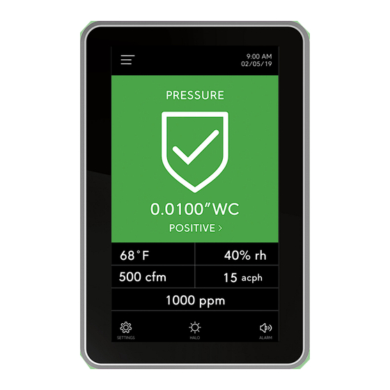
The FMS-2000M provides maximum room status awareness with the color coded visual alarms that display on screen, and the 360° Safety Halo illuminated edge which you can use to easily monitor spaces down long corridors. You can put the audible alarm into snooze mode with one tap to the screen. -
Page 8: Location Considerations
Location considerations Install the FMS-2000M monitor directly outside the monitored space, at the nurses’ station, in the engineering office, or at any other location that you need. Place the sensors away from any moving air source such as ceiling air registers, because this can cause unstable sensor behavior. -
Page 9: Installing The Fms-2000M Thin Mount Display For A Retrofit Application
1/16 in. hex wrench to drive the screw into the monitor until it engages with the tab. After you mount the FMS-2000M monitor, apply power to the monitor. The initial splash screen displays the Johnson Controls logo and the Safety Halo bezel lights up green to represent the current system status. - Page 10 FMS-2000M Figure 3: Retrofit application dimensions Figure 4: Retrofit ring LIT-12013555...
- Page 11 FMS-2000M Figure 5: FMS-2000M Critical Environment Monitor components for a retrofit application Table 3: FMS-2000M Critical Environment Monitor components for a retrofit application Item Component FMS-2000M Critical Environment Monitor Monitor bracket Wall Retrofit ring Mounting screw Set screw LIT-12013555...
-
Page 12: Installing The Fms-2000M Thin Mount Display For A New Application
After you mount the FMS-2000M monitor, apply power to the monitor. The initial splash screen displays the Triatek logo and the Safety Halo bezel lights up green to represent the current system status. - Page 13 FMS-2000M Figure 8: FMS-2000M Critical Environment Monitor components for a new application Table 4: FMS-2000M Critical Environment Monitor components for a new application Item Component FMS-2000M Critical Environment Monitor Mounting bracket Wall Stud Rough-in box Mounting screw Set screw LIT-12013555...
-
Page 14: Mounting The Remote Pressure Sensor
Mounting the remote pressure sensor The FMS-2000M Critical Environment Monitor includes one to four remote pressure sensors to measure the differential pressure of the monitored spaces. Install the remote pressure sensor module in the wall facing the monitored space such as an isolation room. - Page 15 FMS-2000M Figure 9: Standard remote sensor 9-pin side view Reference space Monitored space Table 5: Remote pressure sensor installation components Number Description Gasket Stainless steel flow tube mounting plate Wall section in cut away view Flow tube Stainless steel mounting plate...
-
Page 16: Wiring The System And Bacnet Ms/Tp Communications
Wiring remote pressure sensors to the monitor Supervisory device FMS-2000M Critical Environment Monitor Note: The FMS-2000M does not have an internal end of line resistor. If it is the last device on a trunk segment, install an external resistor. For example, a MS-BACEOL-0. LIT-12013555... -
Page 17: Wiring Two Remote Pressure Sensors To The Monitor
Table 7: Wiring remote pressure sensors to the monitor Callout Component FMS-2000M monitor Supplied remote pressure sensors 1, 2, 3, and 4, in order from left to right Optional door switch Note: Configure the door switch setting on the monitor. It can be normally closed or normally open. - Page 18 FMS-2000M Figure 12: Remote pressure sensor DIP switch configuration for four-sensor models 1 2 3 4 5 6 7 8* 1 2 3 4 5 6 7 8* 1 2 3 4 5 6 7 8* 1 2 3 4 5 6 7 8*...
-
Page 19: Upgrading An Fms-1655M Monitor To An Fms-2000M Monitor
3-position terminal block as well. Connect the 4-position terminal block at the end of the interface cable to the 4-pin header at the back of the FMS-2000M display. If you use a BACnet network, connect the networking cable to the 3-pin header. See Figure 13. -
Page 20: Configuring The Display Module Settings
Configuring the display module settings Figure 14: Run mode and demo mode DIP switches 1 2 3 4 1 2 3 4 Table 10: Monitor DIP switch configurations for the operating modes FMS-2000M DIP switch position Demo mode Run mode Position 1 Position 2... - Page 21 FMS-2000M Objects Analog values Read/Write Availability of analog value objects FMS2M-Bx1x FMS2M-Bx2x FMS2M-Bx3x FMS2M- Bx4x AV-13 Network Variable temperature 3 Read or write AV-14 Differential Pressure low alarm setpoint 3 Read or write AV-15 Differential Pressure low warning setpoint 3...
-
Page 22: Technical Specifications
FMS-2000M Technical specifications Table 15: FMS-2000M Critical Environment Monitor technical specifications Intended use Indoor use Overvoltage category Altitude Up to 2000 m (6562 ft) Pressure range ± 0.2500 in. W.C. (± 62.27 Pa) Alarm range ± 0.2500 in. W.C. (± 62.27 Pa) Display range ±... -
Page 23: Product Code Matrix
FMS-2000M Product code matrix Table 16: FMS-2000M Critical Environment Monitor ordering guide Feature Code letter or number and description Product code number example: LB–FMS2M–BT40 Brand LB = Johnson Controls Unit FMS = Flow Monitor Station (FMS) Series 2 = 2000... -
Page 24: North American Emissions Compliance
Contact Johnson Controls: www.johnsoncontrols.com/contact-us Building Technologies & Solutions Headquarters: Milwaukee, Wisconsin, USA Branch Offices: Principal Cities World-wide © Copyright 2023 Johnson Controls. All specifications and other information shown were current as of document revision and are subject to change without notice. www.johnsoncontrols.com...
Need help?
Do you have a question about the FMS-2000M and is the answer not in the manual?
Questions and answers