Emerson Rosemount 585 Annubar Quick Start Manual
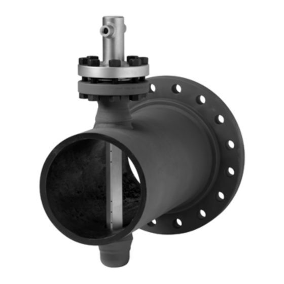
Flanged assembly
Hide thumbs
Also See for Rosemount 585 Annubar:
- Quick installation manual (17 pages) ,
- Quick installation manual (16 pages)

Related Manuals for Emerson Rosemount 585 Annubar


Summary of Contents for Emerson Rosemount 585 Annubar
- Page 1 Quick Start Guide 00825-0100-4585, Rev AB June 2016 ™ ™ Rosemount 585 Annubar Flanged Assembly...
-
Page 2: Table Of Contents
Quick Start Guide NOTICE This guide provides basic guidelines for Rosemount 585 Annubar Assembly. It does not provide instructions for configuration, diagnostics, maintenance, service, troubleshooting, Explosion-proof, Flame-Proof, or intrinsically safe (I.S.) installations. Refer to the Rosemount 585 Reference Manual (document number 00809-0100-4585) for more instruction. - Page 3 Quick Start Guide June 2016 Figure 1. Rosemount 585 Annubar Assembly Exploded View A. Nuts E. Opposite side support B. Remount mount instrument connection F. Sensor flange C. Gasket G. Rosemount 585 Annubar Sensor D. Studs H. Mounting flange assembly...
-
Page 4: Location And Orientation
June 2016 Quick Start Guide 1.0 Location and orientation Correct orientation and straight run requirements must be met for accurate and repeatable flow measurements. Refer to Table 1 for minimum pipe diameter distances from upstream disturbances. Table 1. Straight Run Requirements In plane____________Out of plane Upstream pipe diameters Without... - Page 5 Table 1 applies to gate, globe, plug, and other throttling valves that are partially opened, as well as control valves. 1.1 Misalignment Rosemount 585 Annubar installation allows for a maximum misalignment of 3°. Figure 2. Misalignment ±3° ±3° ±3°...
- Page 6 June 2016 Quick Start Guide 1.2 Horizontal Orientation For proper venting and draining, the sensor should be located in the upper half of the pipe for gas applications. For liquid and steam applications, the sensor should be located in the bottom half of the pipe. Figure 3.
-
Page 7: Drill Holes Into Pipe
Quick Start Guide June 2016 1.3 Vertical Orientation The sensor can be installed in any position around the circumference of the pipe, provided the vents are positioned properly for bleeding or venting. Optimal results for liquid or steam are obtained when flow is up. For steam applications, a 90°... -
Page 8: Assemble And Check Fit-Up
June 2016 Quick Start Guide 5. A second identically sized hole must be drilled opposite the first hole so that the sensor can pass completely through the pipe. To drill the second hole, follow these steps: a. Measure the pipe circumference with a pipe tape, soft wire, or string. (For the most accurate measurement the pipe tape needs to be perpendicular to the axis of flow.) b. -
Page 9: Weld Mounting Hardware
Quick Start Guide June 2016 Figure 5. Fit-up Check for Rosemount 585 with Opposite-Side Support A. Outer Diameter to Flange (ODF) B. Port A C. Port B D. The same within -in. (3 mm) E. Pipe outside diameter 4.0 Weld mounting hardware 1. - Page 10 June 2016 Quick Start Guide DN40 PN16 RF 3.21 (81) DN40 PN40 RF 3.21 (81) DN40 PN100 RF 3.88 (99) 2.0-in. 150# RF 4.13 (105) 2.0-in. 300# RF 4.38 (111) 2.0-in. 600# RF 4.76 (121) 2.0-in. 900# RF 5.88 (149) 2.0-in.
-
Page 11: Insert The Rosemount Annubar Sensor
Quick Start Guide June 2016 2. Place four -in. (6-mm) tack welds at 90° increments. Check alignment of the mounting both parallel and perpendicular to the axis of flow (see Figure 6). If alignment of the mounting is within tolerances, finish weld per local codes. If alignment is outside of specified tolerance, make adjustments prior to making the finish weld. -
Page 12: Mount The Transmitter
June 2016 Quick Start Guide 6.0 Mount the transmitter 6.1 Transmitter mounting, direct mount head with valves It is not necessary to retract the Annubar when direct mounting a transmitter with valves. 1. Place O-rings into grooves on the face of head. 2. - Page 13 Quick Start Guide June 2016 3. For applications above 250 °F (121 °C), impulse piping should have a minimum length of 1 ft. (0,3048 m) for every 100 °F (38 °C) temperature increase over 250 °F (121 °C). Impulse piping must be non-insulated to reduce fluid temperature.
- Page 14 June 2016 Quick Start Guide Name Description Purpose Drain/vent valve Drains (for gas service) or vents (for liquid or steam service) the DP transmitter chambers Drain/vent valve Manifold Isolates high side or low side pressure from the process Manifold Manifold equalizer Allows high and low pressure side access to the vent valve, or for isolating the process fluid Manifold equalizer...
- Page 15 Quick Start Guide June 2016 Steam and liquid service Mount the transmitter below the process piping. Route the impulse piping down to the transmitter and fill the system with cool water through the two tee fittings. Figure 10. Horizontal Steam and Liquid Figure 11.
- Page 16 June 2016 Quick Start Guide Steam on top service For remote mount installations the impulse piping should slope up slightly from the instrument connections on the Rosemount 585 to the cross fittings allowing condensate to drain back into the pipe. From the cross fittings, the impulse piping should be routed downward to the transmitter and the drain legs.
-
Page 17: Product Certifications
EmersonProcess.com/Rosemount. A hard copy may be obtained by contacting our local sales office. European Pressure Equipment Directive (PED) (97/23/EC) Rosemount 585 Annubar — Refer to EC declaration of conformity for conformity assessment Pressure Transmitter — See appropriate Pressure Transmitter QSG 7.3 Hazardous Locations Certifications... - Page 18 June 2016 Quick Start Guide Figure 13. Rosemount 585 Declaration of Conformity...
- Page 19 Quick Start Guide June 2016...
- Page 20 June 2016 Quick Start Guide...
- Page 21 Quick Start Guide June 2016 Rosemount 585 China RoHS 表 表 格 含有 管控物 超 的部件型号列表 Table 1B: List of Rosemount 585 Parts with China RoHS Concentration above MCVs 有害物 Hazardous Substances 部件名称 多 Part Name 六价 多 汞 Polybrominated Hexavalent Polybrominated Lead...
- Page 22 Standard Terms and Conditions of Sale can be found at Emerson FZE P.O. Box 17033, www.Emerson.com/en-us/pages/Terms-of-Use.aspx Jebel Ali Free Zone - South 2 The Emerson logo is a trademark and service mark of Emerson Dubai, United Arab Emirates Electric Co. Annubar, Rosemount, and Rosemount logotype are trademarks of +971 4 8118100 Emerson Process Management.
Need help?
Do you have a question about the Rosemount 585 Annubar and is the answer not in the manual?
Questions and answers