Table of Contents
Advertisement
Quick Links
Link Power LPS2400
Outdoor Industrial 4-Port PoE &
2-Port SFP Network Switch
USER MANUAL
Inscape Data Corporation
1620 Oakland Road, STE D101
San Jose, CA 95131
U.S.A.
© Copyright 2015, Inscape Data Corporation, All Rights Reserved. LinkPower, AirEther, AirGoogle,
and Inscape Data are trademarks of Inscape Data Corporation
Disclaimer: While every effort is made to ensure the information given is accurate, Inscape Data
Corporation does not accept liability for any errors or mistakes which may arise. All information and
specifications are subject to change without notice.
Page | 1
Advertisement
Table of Contents

Related Manuals for Inscape Data Link Power LPS2400


Summary of Contents for Inscape Data Link Power LPS2400
- Page 1 Inscape Data are trademarks of Inscape Data Corporation Disclaimer: While every effort is made to ensure the information given is accurate, Inscape Data Corporation does not accept liability for any errors or mistakes which may arise. All information and specifications are subject to change without notice.
- Page 2 Certification Inscape Data Corporation certifies that this product met its published specifications at time of shipment from the factory. FCC Statement This equipment has been tested and found to comply with the limits for a Class A digital device, pursuant to Part 15 of the FCC Rules. These limits are designed to provide reasonable protection against harmful interference when the equipment is operated in a commercial environment.
- Page 3 Failure to comply with these precautions or with specific warnings elsewhere in this manual violates safety standards of design, manufacture, and intended use of the instrument. Inscape Data Corporation assumes no liability for the customer’s failure to comply with these requirements.
- Page 4 Chassis Power Connection Before connecting or disconnecting ground or power wires to the chassis, ensure that power is removed from the device. To ensure that all power is OFF, locate the circuit breaker on the panel board that services the device, switch the circuit breaker to the OFF position, and tape the switch handle of the circuit breaker in the OFF position.
-
Page 5: Table Of Contents
LED Indicator Description Table: ....................... 9 Connector Layout Diagram: ........................10 Waterproof Ethernet, Fiber Optics, & Power Connector Assembly Diagram ......... 10 Grounding Protection: ..........................10 Grounding the Switch ..........................10 Contacting Inscape Data Sales and Support Offices ................13 Page | 5... -
Page 6: Packing List
AC Power Cable with one 3-PIN AC Power Connector & one Coupler (1) • DC Power Cable with one 4-PIN AC Power Connector & one Coupler (1) (Optional) • (Please contact Inscape Data via sales@inscapedata.com, if you would like to purchase this part) • User Manual (1) •... -
Page 7: Product Description
Product Description LPS2400 Outdoor Industrial PoE Switch features with four PoE Ethernet ports and comply to 10/100/1000BaseT(X), IEEE802.3af PoE and two Gigabit SFP fiber optics interfaces. The power supply of single PoE port can be up to 15.4W. The transfer data can be up to 120Km from SFP fiber port to a control center. -
Page 8: Power Redundancy & Ups Input
Power Redundancy & UPS Input The switch offers dual power redundancy, i.e., AC & DC input. There are two power inputs, as shown below diagram: When the AC input is connected, the AC is the main power input to the switch. To enable the power redundancy, you connect the DC power to the 4-Pin Terminal with a 48V DC and up to 57V DC power source. -
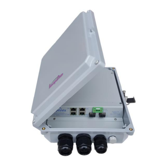
Page 9: Poe Switch Internal View
PoE Switch Internal View : LED Indicator Description Table: Description Indicator Status Green LED ON Power On, Normal PWR Indicator: POWER LED OFF Power OFF Green LED ON Connected PD Device, working properly Green LED Blink Short circuit or current overload PoE Indicator: PoE No Connected PD or Power OFF No Connected PD or Power OFF... -
Page 10: Connector Layout Diagram
Connector Layout Diagram: Please note, the switch supports cable Gland and conduit waterproof connectors. The hole diameter for PoE cables is 25 mm, and the hole diameter for power cable is 20 mm. Support Cable Gland and Conduit Connectors • The hole Size of SFP &... - Page 11 4. If the ground contact in the power outlet is not connected to the ground, report and resolve the problem and reconstruct the grounding system. NOTE: RODUCT DAMAGE CAUSED BY IMPROPER OR NO GROUNDING WILL NOT BE COVERED UNDER WARRANTY U.S.
- Page 12 Page | 12...
-
Page 13: Contacting Inscape Data Sales And Support Offices
Contacting Inscape Data Sales and Support Offices For more information about Inscape Data Corporation products, applications, support, and for a current sales office listing, visit our web site: http://www.inscapedata.com U.S. Headquarters Here’s how to reach us if you’d like to place an order or if you have questions, concerns, or need support...
Need help?
Do you have a question about the Link Power LPS2400 and is the answer not in the manual?
Questions and answers