
Subscribe to Our Youtube Channel
Related Manuals for OMC W150


Summary of Contents for OMC W150
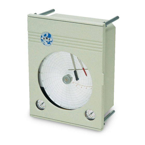
- Page 1 Controllers Recorders Registratori Regolatori ManW150&650ne 04/2014 Installazione, Uso e Manutenzione Registratori Regolatori Grafici a Traccia Continua Continuous Pen Controllers Recorders SERIE W150 W650EP Installation and Maintenance Instructions...
- Page 2 Agente locale o il nostro Servizio di Cernusco s/N - Italy Assistenza Tecnica. OMC s.r.l. - Via Galileo Galilei, 18 - 20060 Cassina de Pecchi (MI) - ITALY Tel.: (+39) 02.95.28.468 - Fax: (+39) 02.95.21.495 - info@omcsrl.com...
- Page 3 1. MONTAGGIO 1. INSTALLATION Gli strumenti sono provvisti di quattro colonnine standard per l'immediato montaggio a quadro o a parete. Su richiesta The instruments are equipped with four standard legs for viene fornita una staffa di montaggio per palina da 2" direct panel or wall mounting.
- Page 4 2. DATI TECNICI 2. TECHNICAL DATA Custodia In alluminio pressofuso, verniciatura antiacida Body and cover Die cast alumunium, corrosion resistant paint Grado di protezione IP54 Degree of protection Montaggio A parete o a quadro Mounting Wall or panel Limite di incertezza max. ...
- Page 5 4. CONNECTIONS 4. CONNESSIONI The pneumatic connections are located at the rear bottom of Tutte le connessioni si trovano sul retro dello strumento. I the instrument housing. The measuring element and the riscontri colorati in prossimità degli attacchi identificano corresponding writing pens are identified by coloured labels, l'elemento di misura e le rispettive penne scriventi.
- Page 6 PENNA CARTRIDGE PENNARELLO Fig. 6 7. WRITING 7. SCRITTURA Gli strumenti vengono forniti con i pennarelli già inseriti The recorders are provided with pre-installed cartridges. sulle rispettive penne. Per la messa in funzione, togliere i When starting the recorder, remove the plastic hoods from cappucci protettivi in plastica dalle punte scriventi.
- Page 7 9. COLLEGAMENTI SCHEDA 9. POTENZIOMETRIC CARD CONNECTIONS POTENZIOMETRICA PRIMA SELEZIONARE BEFORE SELECTING CAMBIARE MODO CHANGING OPERATION FUNZIONAMENTO ACCERTARSI CHE POTENZIOMETRO (ROSSO) MODE, MAKE SURE THAT THE LA SCHEDA NON SIA ALIMENTATA POTENTIOMETER (RED) CARD HAS NOT BEEN FEEDED CORSORE POTENZIOMETRO (GIALLO) MOTORE (ROSSO) POTENTIOMETER SLIDER (YELLOW) MOTOR (RED)
- Page 8 10. CONNECTIONS 10. COLLEGAMENTI PNEUMATICI 10.1. COMPRESSED AIR SUPPLY (Fig.10.1.1) 10.1. COLLEGAMENTO ALLA RETE ARIA The pneumatic connections (1/4"NPT) are located in the COMPRESSA (Fig. 10.1.1) back-housing and are identified by "SUPP" (air supply input) I collegamenti pneumatici (1/4"NPT), si trovano nel retro- "OUT"...
- Page 9 Elemento termometrico a capillare Per regolatori di temperatura W150 Thermometrical element with capillary...
-
Page 10: Messa In Funzione
10.4 REGOLATORE PANNELLO 10.4 AUTOMATIC/MANUAL SELECTION AUTO/MANUALE PANEL MOD.251 Il pannello di commutazione auto-manuale viene impiegato Use the automatic/manual selection panel to override the per escludere la regolazione automatica del processo ed automatic control system, to operate the system manually operare manualmente, oppure quando l'avviamento della or when the control conditions are difficult. - Page 11 3.2. REGOLATORE PROPORZIONALE (P) (Fig. 3.2. PROPORTIONAL CONTROLLER (P) (Fig. 11.2) 11.1) A - Alimentare l'apparecchio con aria a 20 psi (±1,5) e - Apply a 20 psi air supply (±1.5) and open the bleed aprire la vite di spurgo del filtro riduttore di pressione (vedi valve of the pressure reducer filter (see Fig.
- Page 12 E - Se la valvola di regolazione (3) è dotata di by-pass (5), F - Open the cutoff valve (4) situated upstream to the controllare che quest'ultima sia ben chiusa e che la valvola pneumatic valve slowly and completely (see Fig. 10.2.1). d' intercettazione a valle (4) sia completamente aperta (vedi G - If the control setting tends to fluctuate and the writign Fig.10.2.1).
-
Page 13: Manutenzione
12. MANUTENZIONE 12. MAINTENANCE l'ordinaria manutenzione del regolatore agire come Follow instructions indicated below routine segue: maintenance of the control unit: Spurgare giornalmente filtro sulla linea 1) Daily bleed the filter in the air supply line until any water, alimentazione, fino ad espellere completamente le impurità air or other impurities are completely expelled. - Page 14 SINTOMO CAUSA RIMEDIO SYMPTOM CAUSE ACTION TO TAKE Perdita di aria nella Localizzare la perdita ed Air leaks in the control Detect and eliminate the air linea del segnale eliminarla signal line leak regolante Eccessiva ampiezza Proportional band too Decrease. See paragraph della banda Diminuire.
- Page 15 14.2 PULIZIA UGELLO 14.2 FLAPPER-NOZZLE UNIT CLEANING Rimuovere la vite (8) Fig. 14.1.1 estrarre il quadrantino Unscrew the screw (8) (see Fig. 14.1.1). Remove the dial (54), il tubo (9) e pulire, come da Fig. 14.2.2,con l'apposito (54), the tube (9) and clean, as shown in Fig. 14.2.2, by pulitore posto sul coperchio all'interno dello strumento.
- Page 16 14.3 PULIZIA RELAY 14.3 RELAY CLEANING La presenza di olio e condensa nell'aria di alimentazione If there is any oil and condensate in the air supply, clean the potrebbe rendere necessaria la pulizia delle membrane (31) diaphragms (31) and (35) and the other inside elements of e (35) e degli altri organi interni del relay (vedi fig.14.3.2).
- Page 17 SOLO PERFORMED BY AUTHORIZED PERSONNEL ONLY PERSONALE ESPERTO DISPONE CONOSCENZE E MEZZI ADEGUATI. 16.1 SENSITIVE ELEMENT CALIBRATION (SERIE W150) 16.1 TARATURA ELEMENTO SENSIBILE The calibration of the instrument is possible by performing (SERIE W150) three combined standard calibration procedures. They are: Lo strumento viene tarato mediante tre tarature base usate - Zero adjustment;...
- Page 18 16.1.A POTENTIOMETRIC CARD 16.1.A TARATURA SCHEDA CALIBRATION (SERIES W650EP) POTENZIOMETRICA (SERIE W650EP) 1. Simulate a 0% input signal. 1. Simulare un segnale d'ingresso pari allo 0% della scala 2. Turn the sctew of the PT1 trimmer to adjust the black dello strumento.
Need help?
Do you have a question about the W150 and is the answer not in the manual?
Questions and answers