Table of Contents
Advertisement
Quick Links
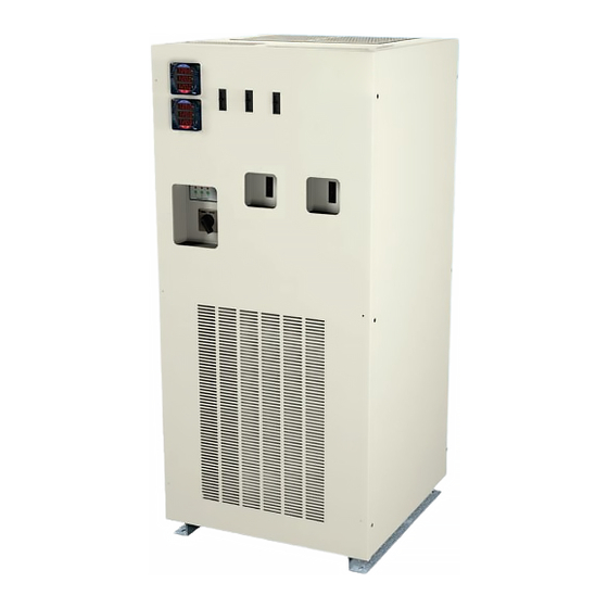
Series 700 AV/T-S Power Conditioner
160K(i) Power Conditioner with
Voltage Regulation (60 Hz)
Owners Manual
Important safety instructions - save these instructions and review prior to using equipment
Quad Output Power Conditioner for Novalis
TX with ExacTRAC and OBI Options
160K(i) 60 Hz Model Front Access Design
▪ 112084-BRL2 Rev 5
Advertisement
Table of Contents

Summary of Contents for Infinite Transtector 700 AV/T-S Series
- Page 1 Series 700 AV/T-S Power Conditioner 160K(i) Power Conditioner with Voltage Regulation (60 Hz) Owners Manual Important safety instructions - save these instructions and review prior to using equipment Quad Output Power Conditioner for Novalis TX with ExacTRAC and OBI Options 160K(i) 60 Hz Model Front Access Design ▪...
-
Page 2: Table Of Contents
160K(i) 60 Hz Power Conditioner | Owners Manual TABLE OF CONTENTS Receiving and Inspecting the Unit General Description Safety Precautions Preliminary Installation Weights, BTU and Dimensions Input Wire Size, Grounding and Output Wiring Installation 10-13 Bypass Switch Start - up and Operation Preventive Maintenance Performance Checklist General Troubleshooting... -
Page 3: Receiving And Inspecting The Unit
RECEIVING & INSPECTING THE UNIT INSPECTING THE POWER PROCESSOR Upon receipt of the unit, visually inspect for shipping damage. If any damage is found, the Purchaser must contact the Carrier immediately and file a shipping damage claim. NOTE: Be sure to remove the front and side panels, and inspect the inside of the unit for shipping damage. If any internal damage has occurred or any external damage that could affect the operation of the unit, please contact Transtector. -
Page 4: General Description
160K(i) 60 Hz Power Conditioner | Owners Manual GENERAL DESCRIPTION The Series 700AV/T-S Power Processor is designed to supply reliable, clean regulated power to critical loads. An efficient design with state of the art micro-processor controlled solid state devices provide immunity to all line disturbances. -
Page 5: Safety Precautions
SAFETY PRECAUTIONS **** WARNING **** THERE ARE DANGEROUSLY HIGH VOLTAGES PRESENT WITHIN THE ENCLOSURE OF THE POWER SUPPLY SYSTEM. CAUTION MUST BE TAKEN WHEN WORKING WITH THE SYSTEM. IT IS RECOMMENDED THAT ALL WORK BE PERFORMED BY QUALIFIED ELECTRICAL PERSONNEL ONLY. **** CAUTION **** RISK OF ELECTRICAL SHOCK AND HIGH SHORT CIRCUIT CURRENT. -
Page 6: Preliminary Installation
160K(i) 60 Hz Power Conditioner | Owners Manual PRELIMINARY INSTALLATION INSTALLATION CONSIDERATIONS Prior to installing the Series 700AV/T-S, be sure to take into consideration the site you have selected. Power Conditioners produce heat and therefore require ventilation as well as accessibility. Consider these factors. -
Page 7: Weights, Btu And Dimensions
PRELImINARY INSTALLATION (continued) INPUT AND OUTPUT BREAKER SIZE OUTPUT KVA INPUT OUTPUT BREAKER SIZE MAX OUTPUT CURRENT CONTINUOUS BREAKER SIZE 75 kVA 300A @ 208V 150A, 3P @ 208V Accelerator 208/120V 125A Accelerator 250A @ 240V 70A, 3P @ 480V BL Generator 480/277V 70A BL Generator 150A @ 480V 60A, 3P @ 480V OBI... -
Page 8: Input Wire Size, Grounding And Output Wiring
160K(i) 60 Hz Power Conditioner | Owners Manual INPUT wIRE SIZE, gROUNdINg ANd OUTPUT wIRINg NOTE: Refer to the latest edition of The National Electric Code Requirements for over-current protection and wire sizing. Refer to the latest edition of The National Electric Code Requirements for over-current protection and wire sizing. - Page 9 INPUT wIRE SIZE, gROUNdINg ANd OUTPUT wIRINg (continued) F. Continued Output wiring sizes: 208/120 VAC 150 Amp breaker #14 AWG to #3/0 AWG 480/277 VAC 70 Amp breaker #14 AWG to #3/0 AWG 480/277 VAC 60 Amp breaker #14 AWG to #3/0 AWG 120 VAC 30 Amp breaker #14 AWG to #2 AWG...
-
Page 10: Installation
160K(i) 60 Hz Power Conditioner | Owners Manual INSTALLATION CABINET OUTLINE - FRONT VIEW FRONT VIEW INPUT OUT OF RANGE ALERT OUTPUT CONDITIONED POWER 76.000 AIR INLET 3.000 BOTTOM VIEW 34.500 Ø.562 x 1.000... - Page 11 INSTALLATION (continued) CABINET OUTLINE - TOP AND BOTTOM VIEW TOP VIEW 23.000 5.690 3.716 REMOVABLE TOP PANEL PROVIDES ACCESS TO TRANSFORMER, 15.875 OUTPUT FILTER, OUTPUT TERMINATIONS AND CURRENT TRANSFORMERS. (4)Ø.875 KNOCK-OUTS TOP INPUT/OUTPUT 14.000 TERMINATION ACCESS AREA 6.895 FRONT 34.500 Ø.562 x 1.000 30.271 2.469...
- Page 12 160K(i) 60 Hz Power Conditioner | Owners Manual INSTALLATION (continued) CABINET OUTLINE - RIGHT SIDE VIEW AIR FLOW RIGHT SIDE VIEW OPTIONAL SIDE OUTPUT TERMINATION ACCESS AREA 8.250 4.850 2.810 4.500 35.500...
- Page 13 INSTALLATION (continued) INPUT AND OUTPUT CONNECTIONS 1. Input connections are made directly to the unit’s 3 pole main input circuit breaker and input lug provided. Note the bottom access wire run route illustrated below. 2. Output connections are made directly to the output breaker(s) and output neutral and ground lugs provided.
-
Page 14: Bypass Switch
160K(i) 60 Hz Power Conditioner | Owners Manual BYPASS SWITCH **** CAUTION **** Prior to switching from one position to another- turn off the AC input breaker. The manual bypass switch is a break before make switch located on the Series 700 AV/T-S. The manual bypass switch is used to bypass all power electronics in case of failure. -
Page 15: Start - Up And Operation
START UP **** WARNING **** THERE ARE DANGEROUSLY HIGH VOLTAGES PRESENT WITHIN THE ENCLOSURE OF THE POWER SUPPLY SYSTEM. CAUTION MUST BE TAKEN WHEN WORKING WITH THE ENCLOSURE. IT IS RECOMMENDED THAT ALL WORK BE PERFORMED BY QUALIFIED ELECTRICAL PERSONNEL ONLY. NOTE: INITIAL START-UP SHOULD BE PERFORMED WITH NO LOAD ON SYSTEM. -
Page 16: Preventive Maintenance
160K(i) 60 Hz Power Conditioner | Owners Manual PREVENTIVE MAINTENANCE **** WARNING **** dANgER OF ELECTRICAL ShOCK, TURN OFF ALL POwER SUPPLYINg ThIS EqUIPmENT PRIOR TO MAINTENANCE. To ensure longer component life and trouble-free operation, minor preventive maintenance procedures should be performed at regular intervals, for example once every year. More frequent inspection intervals would be needed for more severe operating conditions and larger number of hours of continuous operation. -
Page 17: Performance Checklist
PERFORMANCE CHECKLIST Company______________________________________________________________ Model #____________________________Serial #__________________ Customer Comments or Problems____________________________________ Power Processor Environment Clean and Dust Free Yes_______ No________ Phase Rotation Correct (ABC) Yes_______ No________ Electrically wired properly ie...Conductor Sizing, Breakers, Grounding Verify Input Voltage (See specification tag) Check Tightness of Electrical Connections: ______Input Connections______Output Connections______Heatsink Connections (SCR’s) ______Circuit Board Connections______By-Pass Switch______Fuse Connections ______Fan Connections______Transformer Connections... -
Page 18: General Troubleshooting
160K(i) 60 Hz Power Conditioner | Owners Manual GENERAL TROUBLESHOOTING **** WARNING **** THERE ARE DANGEROUSLY HIGH VOLTAGES PRESENT WITHIN THE ENCLOSURE OF THE POWER SUPPLY SYSTEM. CAUTION MUST BE TAKEN WHEN WORKING WITH THE ENCLOSURE. IT IS RECOMMENDED THAT ALL WORK BE PERFORMED BY QUALIFIED ELECTRICAL PERSONNEL ONLY. -
Page 19: Parts List
PARTS LIST 208 V INPUT 240 V INPUT 480 V INPUT 600 V INPUT DESCRIPTION PART # PART # PART # PART # 112640 112640 112640 112640 OUTPUT METER 204936 204936 204418 204420 MAIN TRANSFORMER 204518 204518 204518 204518 AUTO TRANSFORMER 11173 11173 11173... -
Page 20: Warranty
160K(i) 60 Hz Power Conditioner | Owners Manual WARRANTY WARRANTY VALIDATION WARRANTY VOID UNLESS THIS FORM IS COMPLETE AND RETURNED TO TRANSTECTOR SYSTEMS Transtector Systems, Inc. warrants that the Series 700 AV/T-S Power Conditioner and its components will remain free from defects in material and workmanship for the period of two (2) years from the date of shipment and agrees to replace F.O.B. - Page 21 APPENDIX A RELATIVE DRAWINGS & SCHEMATICS 1402-001...
-
Page 22: Cabinet Layout
160K(i) 60 Hz Power Conditioner | Owners Manual CABINET LAYOUT... - Page 23 CABINET LAYOUT 1402-001...
- Page 24 160K(i) 60 Hz Power Conditioner | Owners Manual CABINET LAYOUT NO CLEARANCE REQUIRED...
-
Page 25: Seismic Calculations
SEISMIC CALCULATIONS Coastal California, Zone 4 Z = 0.4 Equipment Anchorage I = 1.5 Uniform Building Code, Table 160 Cp = 0.75 Fp = Z x I x (Cp) x Wp = 0.45 x Wp Cabinet Weight 2194 lbs. Center of Gravity Height 33.00 in. -
Page 26: Symbol Library
160K(i) 60 Hz Power Conditioner | Owners Manual SYMBOL LIBRARY This symbol indicates that caution should be taken when performing the process required in this manual. Damage to the unit or personal harm could happen if proper precautions are not taken. Caution This symbol indicates that there is a risk of electrical shock if proper precau- tions are not followed. -
Page 27: Notes
NOTES 1402-001...
Need help?
Do you have a question about the Transtector 700 AV/T-S Series and is the answer not in the manual?
Questions and answers