Advertisement
Quick Links
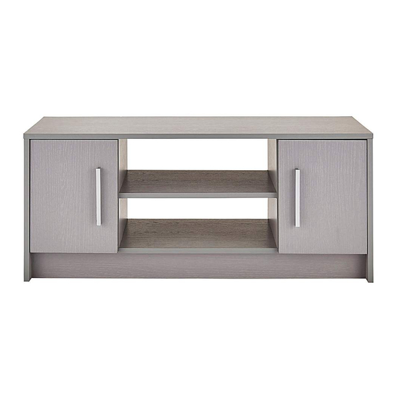
2 Door Entertainment Unit
Assembly Instructions
033 xx 5520
- Please keep for future reference
Dimensions
Width - 98.4cm
Depth - 38.8cm
Height - 41.5cm
MADE IN
GREAT BRITAIN
Important -
Please read these instructions fully before starting assembly
If you need help or have damaged or missing parts, call the Customer Helpline: 01709 534123
Please turn to back page for important information when contacting Customer Helpline.
Rev B - 20/03/17
Advertisement

Subscribe to Our Youtube Channel
Related Manuals for J D Williams Norton TV Unit TD465


Summary of Contents for J D Williams Norton TV Unit TD465
- Page 1 2 Door Entertainment Unit Assembly Instructions 033 xx 5520 - Please keep for future reference Dimensions Width - 98.4cm Depth - 38.8cm Height - 41.5cm MADE IN GREAT BRITAIN Important - Please read these instructions fully before starting assembly If you need help or have damaged or missing parts, call the Customer Helpline: 01709 534123 Please turn to back page for important information when contacting Customer Helpline.
- Page 2 Safety and Care Advice Important - Please read these instructions fully before starting assembly Do not stand or put weight on Check you have all the We do not the product, this could cause components and tools listed on recommend the damage.
- Page 3 If you have damaged or missing panels, call the Components - Panels Customer Helpline: 01709 534123 Please turn to back page for important information when contacting Customer Helpline. Please check you have all the panels listed below Important - Thick lines indicate finished edges 9678 0706...
- Page 4 If you have damaged or missing components, call the Components - Fittings Customer Helpline: 01709 534123 Please turn to back page for important information when contacting Customer Helpline. Please check you have all the fittings listed below Note: The quantities below are the correct amount to complete the assembly, In some case more fittings may be supplied than are required.
-
Page 5: Exploded View
Exploded View 9664 9657 9664 9663 9678 9659 9662 9660 0706 9656 9663 9658 0706 9148... - Page 6 Assembly Instructions Step 1 Fitting cams to the bottom panel. Insert 4 metal cams into the bottom panel 9656 Note: Ensure cam arrow points towards the edge 9656 with the hole. Step 2 Fitting cams to the plinth panel. Insert 4 metal cams to the plinth panel 9148 9148...
- Page 7 Assembly Instructions Step 4 Attach dowels, cams and hinges to both of the end panels. Insert 4 metal dowels 2 hinges and 2 cams into the left end 9657 panel Repeat on the right end panel 9658 9657 9658 Step 5 Attach dowels, cams and hinges to both of Holes not used at...
- Page 8 Assembly Instructions Correct Step 6 Attach hinges and handles to the doors Incorrect Insert hinges into holes, ensure the hinge is straight (90 degree angle). 0706 Bradawl Before securing the hinges , we recommend you pre - mark the doors 0706 using a bradawl.
- Page 9 Assembly Instructions Step 7 Fitting cams to the shelf panel. Insert 4 metal cams to the plinth panel 9662 9662 Step 8 Connect the divider Edged face panels to the large shelf panel. Connect the dowels in the 9659 9659 left divider 9660 right divider...
- Page 10 Assembly Instructions Step 10 Connect the bottom and the plinth panel to the left end panel. Connect the dowels in the 9148 left end panel 9657 the cams in the bottom 9656 panel and the 9148 plinth panel 9657 9656 Step 11 Connect the right end panel to the top,...
- Page 11 Assembly Instructions Step 12 Secure the bottom panel to the divider panels. Using 4 screws secure the bottom panel 9656 to the left divider 9659 and the right divider 9660 9656 9659 9660 Step 13 Squaring up the unit. DIAG 2 DIAG 1 DIAG 3 Important:...
- Page 12 Assembly Instructions Step 14 Attach the backpanel Use the panel pin guide when locating the panel pins. This will hold the panel pins vertical and ensure the correct distance from the edge. Step 15 Fitting the shelf supports. Insert 8 shelf supports Once inserted, seat the shelves on top of the shelf supports.
- Page 13 Assembly Instructions Step 16 Hanging doors With help, slot door hinges onto hinge plates. Ensure screw on hinge slides into the slot on hingeplate. See Diagrams 1, 2 and 3. 0706 Tighten screw shown to lock hinges in position. See ‘Hinge adjustment’ page if the doors need adjusting.
- Page 14 Assembly Instructions Step 17 Hinge adjustment To move doors up or down: loosen screws shown and move doors to suit. Re-tighten screws. To move doors in or out: loosen screw shown and move doors to suit. Re-tighten screws. To move doors left or right: loosen or tighten screw as shown.
- Page 15 Assembly Instructions Congratulations! Your unit is complete. Important Information If you need help or have damaged or missing parts, call the Customer Helpline: 01709 534123 8am - 4.30pm (Monday to Thursday) 8am - 2.30pm (Fridays) (by contacting the customer service line your statutory rights are not affected) Please have the following information to hand: >>...
Need help?
Do you have a question about the Norton TV Unit TD465 and is the answer not in the manual?
Questions and answers