Advertisement
Quick Links
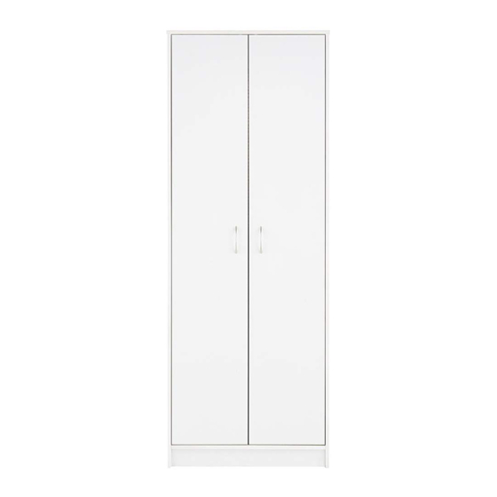
2 Door Robe
Assembly Instructions
001 xx 8583
- Please keep for future reference
Dimensions
Width - 66.8cm
Depth - 49.8cm
Height - 179.9cm
MADE IN
GREAT BRITAIN
Important -
Please read these instructions fully before starting assembly
If you need help or have damaged or missing parts, call the Customer Helpline: 01709 534 123
Please turn to back page for important information when contacting Customer Helpline.
Rev A - 06/03/2018
Advertisement

Subscribe to Our Youtube Channel
Related Manuals for J D Williams Darwen XK943


Summary of Contents for J D Williams Darwen XK943
- Page 1 2 Door Robe Assembly Instructions 001 xx 8583 - Please keep for future reference Dimensions Width - 66.8cm Depth - 49.8cm Height - 179.9cm MADE IN GREAT BRITAIN Important - Please read these instructions fully before starting assembly If you need help or have damaged or missing parts, call the Customer Helpline: 01709 534 123 Please turn to back page for important information when contacting Customer Helpline.
- Page 2 Safety and Care Advice Important - Please read these instructions fully before starting assembly Do not stand or put weight on Check you have all the We do not the product, this could cause components and tools listed on recommend the damage.
- Page 3 Components - Panels Please check you have all the panels listed below Important - Thick lines indicate finished edges 0280 (66.8x49.8cm) 0281 Bottom (63.4x49.5cm) 9821 0282 Door x 2 0283 (168.4x31.3cm) Left End Panel Right End Panel (178.4x49.6cm) (178.4x49.6cm) 4899 Back Rail (63.4x12.4cm) 740006000...
- Page 4 If you have damaged or missing components, call the Components - Fittings Customer Helpline: 01709 534 123 Please turn to back page for important information when contacting Customer Helpline. Please check you have all the fittings listed below Note: The quantities below are the correct amount to complete the assembly, In some case more fittings may be supplied than are required.
-
Page 5: Exploded View
Exploded View 0280 0282 4899 0133 9821 0283 9821 0281 8553... - Page 6 Assembly Instructions Step 1 Fitting dowels to top panel. Insert 4 metal dowels and 2 door stoppers into the top panel 0280 Note: Tighten the metal dowels up fully against 0280 the panel. Do not over-tighten. A hammer may be required to insert the door stopper.
- Page 7 Assembly Instructions Step 4 Fitting hanging rail support & hingeplates to left end. Insert 3 hinge plates into the left end panel 0282 Insert 2 screws through the holes in the hanging rail support Note: A bradawl may be 0282 required when attaching the hanging rail support to create the lower hole.
- Page 8 Assembly Instructions Step 6 Fitting cams & dowels to the left end panel. Insert 6 metal dowels and 2 cams into 0282 left end panel 0282 Step 7 Fitting cams & dowels to the right end panel. Insert 6 metal dowels and 2 cams into 0283...
- Page 9 Assembly Instructions Correct Step 9 Attach hinges and the handles to the doors Insert hinges into holes, ensure the hinge is straight (90 degree angle). 9821 Before securing the Bradawl hinges , we recommend you pre - mark the doors using a bradawl.
- Page 10 Assembly Instructions Step 10 Connect left end to the plinth, bottom and back rail. Connect the dowels in 0282 the left end to the 8553 cams in the plinth the bottom 0281 and the back rail 4899 0282 We recommend that 2 people for this step, to 4899 hold the back rail in...
- Page 11 Assembly Instructions Step 12 Connect right end and left end to the top panel. Connect the dowels in 0280 0280 the top panel to the 0283 cams in right end 0282 and the left end 0282 0283 Step 13 Squaring up the unit. IMPORTANT Ensure a tape measure is used...
- Page 12 Assembly Instructions Step 11 Step 14 Attach the back panel to the unit. Use the panel pin guide when locating the panel pins. This will hold the panel pins vertical and ensure the correct distance from the edge. 8566 0281 Plain chipboard surface.
- Page 13 Assembly Instructions Step 15 WARNING Fixing to wall IN ORDER TO PREVENT OVERTURNING We recommend that this THIS PRODUCT MUST BE USED WITH THE WALL ATTACHMENT DEVICE unit is fixed to a suitable PROVIDED wall to prevent possible Serious or fatal crushing injuries can occur from overbalancing.
- Page 14 Assembly Instructions Step 16 Hanging doors With help, slot door hinges onto hinge plates. Ensure screw on hinge slides into the slot on hingeplate. See Diagrams 1, 2 and 3. Tighten screw shown to lock hinges in position. See ‘Hinge adjustment’ page if the doors need adjusting.
- Page 15 Assembly Instructions Step 17 Hinge adjustment To move doors up or down: loosen screws shown and move doors to suit. Re-tighten screws. To move doors in or out: loosen screw shown and move doors to suit. Re-tighten screws. To move doors left or right: loosen or tighten screw as shown.
- Page 16 Assembly Instructions Congratulations! Your unit is complete. Important Information If you need help or have damaged or missing parts, call the Customer Helpline: 01709 534 123 8am - 4.30pm (Monday to Thursday) 8am - 2.30pm (Fridays) (by contacting the customer service line your statutory rights are not affected) Please have the following information to hand: >>...
Need help?
Do you have a question about the Darwen XK943 and is the answer not in the manual?
Questions and answers