Viconics VT8000 Series Installation Manual
Room controllers, line voltage fan coil unit (fcu)
Hide thumbs
Also See for VT8000 Series:
- User manual (85 pages) ,
- User interface manual (82 pages) ,
- Installation & quick start manual (19 pages)

Related Manuals for Viconics VT8000 Series


Summary of Contents for Viconics VT8000 Series
- Page 1 VT8000 Room Controllers VTR8350 Installation Guide Line Voltage Fan Coil Unit (FCU) Version 9...
-
Page 2: Table Of Contents
INSTALLATION ............................. 7 TERMINAL IDENTIFICATION AND FUNCTION ..................... 8 COMMUNICATION WIRING TO VC3000 RELAY PACK ................. 8 HOME SCREEN DISPLAY ..........................9 ENTER SET-UP SCREEN ........................... 10 SET-UP SCREEN DISPLAY ........................10 APPENDIX A. DEPLOYMENT ........................11 028-0414-09_II-VTR8350_A4_EN www.viconics.com May 2020... -
Page 3: Safety Information
Electrical equipment should be installed, operated, serviced, and maintained only by qualified personnel. No responsibility is assumed by Viconics Technologies for any consequences arising out of the use of this material. A qualified person is one who has skills and knowledge related to the construction, installation, and operation of electrical equipment and has received safety training to recognize and avoid the hazards involved. - Page 4 • Refer to the Room Controller User Interface Guide for information on how to configure the Room Controller. Failure to follow these instructions can result in equipment damage. 028-0414-09_II-VTR8350_A4_EN www.viconics.com May 2020...
- Page 5 • Do not drop or crush the Room Controller, or allow it to come into contact with liquids. • Do not use a damaged device (such as one with a cracked screen). Failure to comply with these recommendations will result in damage to the unit and void the manufacturer’s warranty. 028-0414-09_II-VTR8350_A4_EN www.viconics.com May 2020...
-
Page 6: Important Symbols
Amendment 1, or a later version of the same standard incorporating the same level of testing requirements. Alternating Current Direct Current Equipment protected throughout by DOUBLE INSULATION or REINFORCED INSULATION VTR8350 Room Controller VC3000 Relay Pack 028-0414-09_II-VTR8350_A4_EN www.viconics.com May 2020... -
Page 7: Installation
11. Gently push excess wiring back into hole. 12. Gently align cover to top of base and snap in place from bottom (Figure 3). 13. Install security screw. Figure 2 Install the base Figure 3 Reinstall cover 028-0414-09_II-VTR8350_A4_EN www.viconics.com May 2020... -
Page 8: Terminal Identification And Function
Network Wiring Topology Star Topology Daisy Chained Topology Mixed Daisy Chained & Star Topology NOTE: • Only one VC3404 or VC3504 Relay Pack with remote monitoring inputs can be used for a single VTR8350 Room Controller. 028-0414-09_II-VTR8350_A4_EN www.viconics.com May 2020... -
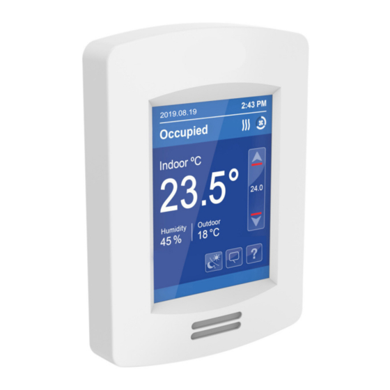
Page 9: Home Screen Display
NOTE: User HMI is configurable and allows display functions such as Date, Time, Humidity, Outdoor Temperature, Setpoint, and others to be enabled or disabled by setting various parameters. Outdoor temperature displayed only on controllers connected to relay packs. 028-0414-09_II-VTR8350_A4_EN www.viconics.com May 2020... -
Page 10: Enter Set-Up Screen
Enter setpoint settings D i sp l ay Enter display settings Ser vice view Enter status display (read only) Tes t Ou tpu ts Enter test outputs settings General Note: Adjustable parameter Return to home screen Non-adjustable parameter 028-0414-09_II-VTR8350_A4_EN www.viconics.com May 2020... -
Page 11: Appendix A. Deployment
Moreover, for each case aforementioned, occupant movement almost always moves lateral to the PIR, which ensures detection by the PIR, as well as respecting the PIR detection range of 20 feet (6 meters) at 140°, and 16 feet (5 meters) between 15° to 30° laterally. Recommended Installation 028-0414-09_II-VTR8350_A4_EN www.viconics.com May 2020... - Page 12 PIR would get blocked, and therefore, occupancy going undetected. For the Room Controller installed beside the reception area, occupant traffic could fall outside the detection zone, and the receptionist would often be below the 5 foot recommended installation height for the Room Controller. Non-Recommended Installation 028-0414-09_II-VTR8350_A4_EN www.viconics.com May 2020...
- Page 13 Good energy savings logic and better guest experience even when the experience (when guest is sleeping or not moving) guest is sleeping or not moving Install additional motion sensor in the bathroom. Install additional motion sensor for better motion detection in the entire room. 028-0414-09_II-VTR8350_A4_EN www.viconics.com May 2020...
- Page 14 PIR can maximize your energy saving from 10-30% by adjusting temperature set points in unoccupied zones during scheduled periods. Typical Savings of 10-30% PIR can maximize your energy saving from 10-30% by adjusting temperature set points in unoccupied zones during scheduled periods. Time of Day (EST) Typical Consumption PIR Thermostat Consumption Savings 028-0414-09_II-VTR8350_A4_EN www.viconics.com May 2020...
Need help?
Do you have a question about the VT8000 Series and is the answer not in the manual?
Questions and answers