Midco Blue Flame Series Installation And Service Instructions Manual

Midco Blue Flame Series Installation And Service Instructions Manual

Direct-fired gas burners

Advertisement

Installation and Service Instructions
MADE in the USA
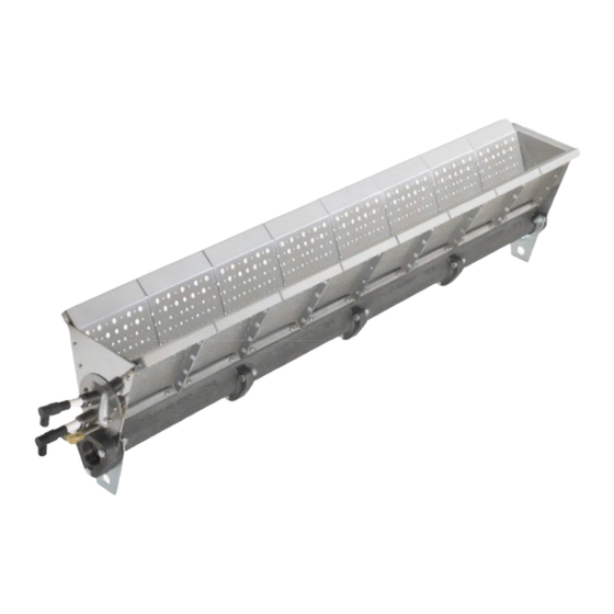
The Blue Flame Series
DIRECT FIRED MAKE-UP AIR BURNERS are used in
industrial and commercial applications to maintain the
desired environmental temperatures required by critical
processes i.e. health purposes, production systems,
quality control, comfort and loss prevention where it
is necessary or required to exhaust large amounts of
conditioned air.
Make-up Air Systems used as stand alone heating
systems or operating in combination with central heating
plants systems can be cost eff ective in three ways: 1)
reducing the initial expenditures, 2) tempering incoming
air which may extend the life of expensive central heating
plants and 3) reducing excessive equipment cycling or
premature component failures due to increased heating
demands.
Our innovative two stage combustion burner is not just a
modifi cation or improvement of the old, but a completely
new approach to direct-fi red combustion. The two-stage
combustion improves control of the fl ame process, meets
or exceeds the new ANSI Standards while outperforming
the competition. By incorporating two separate fl ames
within the burner combustion zone, the fl ame is more
stable, shorter and cleaner, permitting the reduction of
emissions levels and allowing for higher temperature rise
and higher tolerance to varying conditions when placed in
the profi le opening.
®
Midco
International Inc.
4140 West Victoria Street
Chicago, Illinois 60646
toll free 866.705.0514
tel
773.604.8700
fax
773.604.4070
web
www.midcointernational.com
e-mail sales@midcointernational.com
Direct-Fired Gas Burners
Reduced NO
levels that pass the ANSI Z83.4, Z83.18 and Z83.25 standards.
Higher Temperature Rise: The two stage combustion
process lowers NO
temperature rise.
Increased Capacity: Up to 750,000 BTU'S per foot. (Higher
BTU levels can be achieved if ANSI Z83 Standards for CO and
NO
emissions are not of a concern. Process heaters can fi re
2
up to 1,000,000 BTU'S a foot or more.)
Increased Diff erential Pressure Drop and Higher Velocities:
HMA 2 & 2A burners can operate as low as 0.05" to 1.4" W.C.
diff erential pressure range or in air velocity as low as 800 fpm to
4000 fpm.
Flame Stability: Two stage combustion provides better fl ame
stability and emission control, allowing for a shorter fl ame and
easier profi le confi guration.
Reduced Inventory Costs - HMA 2A: Single burner casting
can be fi red with natural, propane or butane gas
burner inventory.
Reduced Shipping Costs: A smaller, lighter casting than the
competition's, can lower your freight costs.
Turndown: 30-1 turndown can be achieved with proper
modulating controls and valves. (Higher turndown possible
depending on equipment design.)
Emission performance is application specifi c and may vary.
Consult Midco for applications using butane fuels.
1
Quality Designed for Proven Performance
HMA 2 &
HMA 2A
Features and Benefi ts
and CO Emissions: Lower emissions
2
emissions which is the limiting factor in
2
, reducing
1
1219
8471 34
Printed in USA

Advertisement

Table of Contents
loading
Need help?

Need help?

Do you have a question about the Blue Flame Series and is the answer not in the manual?

Questions and answers

Summary of Contents for Midco Blue Flame Series

  • Page 1 Turndown: 30-1 turndown can be achieved with proper modulating controls and valves. (Higher turndown possible depending on equipment design.) Emission performance is application specifi c and may vary. Consult Midco for applications using butane fuels. ® Midco International Inc. 4140 West Victoria Street Chicago, Illinois 60646 toll free 866.705.0514...
  • Page 2: Specifications

    Table 1 - Burner and Pilot Confi gurations Midco International Inc. reserves the right to change the construction or confi guration of its products at any time. All information is based on laboratory testing. Diff erent unit size and/or confi gurations may aff ect data.
  • Page 3 350,000 Btu/hr/ft at 0.35" W.C. pressure drop across the burner 350,000 Btu/hr/ft at 0.35" W.C. pressure drop across the burner .45 Delta P .64 Delta P .85 Delta P * For higher temperature rise contact Midco Engineering Department. NOTE: Emission performance is 100000 200000 300000 400000...
  • Page 4 Chart 3- BTU’s verses Gas Pressure ( ″W.C.) 4,500 4,000 3,500 3,000 2,500 2,000 1,500 1,000 0.20 0.40 0.55 0.60 0.80 1.00 1.20 Chart 4 - Pressure Across the Burner verses Profi le Velocity ___________________________________ 8471 34 Midco Inc. International...
  • Page 5: Installation

    Chart 5 - HMA 2 & 2A Flame Length HMA 2 & HMA 2A fl ame length as a function of pressure drop and fi ring rate applies to push and pull through systems using 100% fresh standard air. 8471 34 Midco International Inc.
  • Page 6 0.65 sq. ft. T Section 0.77 sq. ft. Ell Section 0.65 sq. ft. Total Burner Area = 1.0 (ft) x 0.65 = 0.650 ft Total Burner Area = 1.5 (ft) x 0.65 = 0.975 ft 8471 34 Midco Inc. International...
  • Page 7 Temperature diff erence -- Temperature Rise = T (out) (in) Energy equation - - BTU/hr = SCFM x Temperature Rise x 1.08 / 0.92 Where: 1.08 is a sensible heat equation constant 1.08 = 0.2397 x 60 x 0.075 ____ ___________________________________ 8471 34 Midco International Inc.
  • Page 8 12" Figure 1a - Burner Placement in the Profi le 4" 4" 1" to 4", typical 2" Air Flow Burner should be Centered to the Blower Figure 1b - Burner Placement in the Profi le 8471 34 Midco Inc. International...
  • Page 9 Factors such as airfl ow around the burner, positioning in the profi le, as well as, the profi le sizing Continued have infl uence on the fi nal emissions levels . Midco does not guarantee combustion results prior to performing actual combustion tests.
  • Page 10 Pilot Tube * A manifold pressure tap needs to be provided Pilot at the burner to check Regulator Manual Pilot Pilot manifold pressure Pilot Gas Pressure Tap Valve Valve Figure 5a - Gas Train Assemblies 8471 34 Midco Inc. International...
  • Page 11 With the burner off check the Flame Safety Air Proving System Check the operation of the air proving system for low and high airfl ow setting. Refer to the Specifi cations of the Flame Safety Control for setup instructions and air switch operational characteristics. 8471 34 Midco International Inc.
  • Page 12 If the end plates redness occurs during high and intermediate fi re inputs, the distance between the end plates and the profi le opening might not be suffi cient for the air to cool the end plates. Profi le readjustments might be necessary. ___________________________________ 8471 34 Midco Inc. International...
  • Page 13: Burner Trouble Shooting

    Burner Trouble Shooting The Midco Burner is only a component of the complete system. For trouble shooting of the equipment contact the OEM (Original Equipment Manufacturer) or the component manufacturer. If the pilot fails to light: install a manometer on the pilot pressure tap. Check for 3.5″ W.C. for natural gas or 2″...
  • Page 14: Burner Confi Guration

    8.63" 8.63" 11.38" 11.38" 10.47" 2" NPT 2" NPT Inlet Inlet 6.00" 6" Straight with 12" Straight with Elbow 2" NPT Back Inlet 2" NPT Back Inlet Section Figure 6 - Burner Sections - Assembly 8471 34 Midco Inc. International...
  • Page 15 Location of First Burner Port Plug - See Installation, Burner Setup Section or Trouble Shooting Section (Used on high fire start systems ONLY) 5.57" 2.96" 1/8" 3.72" Brute Pilot Pilot Detail - Spark Gap Measurement 1190850 Figure 7 - Pilot Confi guration 8471 34 Midco International Inc.
  • Page 16 Parts - Isometric View - HMA 2 & HMA 2A 2” Straight Ell Section 6” Straight Tee Section 12” Straight Figure 8 - Typical Burner Assembly Parts - Isometric View 8471 34 Midco Inc. International...
  • Page 17 * See above listing for proper selection 25 5/16-18x 1-3/4″ Hex Head Cap Screw Hardware Not Shown 5/16 Lock Washer Hardware 5/16-18 Hex Nut Hardware Burner Confi gurations: see page 14 for complete burner sections Table 5 - Burner Assembly Parts 8471 34 Midco International Inc.
  • Page 18 If Installing mounting brackets, they must be Installed on the exterior side of the Inlet or blank fl ange. UNDER NO CIRCUMSTANCES SHOULD THEY BE INSTALLED BETWEEN THE FLANGE AND THE BURNER CASTING. ___________________________________ Midco ® International Inc. - 4140 West Victoria Street - Chicago, Illinois 60646 - toll free: 866 705 0514 1219 9001 tel: 773.604.8700 - fax: 773.604.4070 - web: www.midcointernational.com - e-mail: sales@midcointernational.com...

This manual is also suitable for:

Hma 2Hma 2a

Table of Contents