Midco Economite 400B-02 Series Installation And Service Instructions Manual
Conversion burners
Hide thumbs
Also See for Economite 400B-02 Series:
- Installation and service instructions manual (13 pages)
Advertisement
Quick Links
Installation and Service Instructions
MADE
in the
USA
• In the United States, installation must conform with local codes or in
the absence of local codes, with the National Fuel Gas Code, ANSI
Z223.1-latest edition available from American National Standard
Institute. Installation of Domestic Gas Conversion Burners, ANSI
Z21.8a- latest edition and National Fuel Gas Code, ANSI Z223.1-
latest edition(s) available from American National Standard Institute.
Further reference should be made to the recommendation of your
fuel supplier.
• In Canada, installation must conform with local codes or in the
absence of local codes, with Installation Codes for Gas Burning
Appliances and Equipment, CGA Standard CAN/CGA 1-B-149.1
or 2. When the conversion burner is used on a Forced Air Central
Furnace, the two yellow and black warning labels in the literature
envelope shall be attached in accordance with Installation Code,
CGA Standard CAN/CGA 1-B149, Clause 5.4.4.4. Further reference
should be made to the recommendation of your fuel supplier.
•
WARNING: Additions, changes, conversions and service
must be performed by an authorized Midco representative,
service agency or the fuel supplier. Use only MIDCO specifi ed
and approved parts.
• INSTALLER: Inform and demonstrate to the user the correct
operation and maintenance of the gas utilization equipment. Inform
the user of the hazards of storing fl ammable liquids and vapors
in the vicinity of this gas utilization equipment and remove such
hazards. Affi x this manual and associated literature to the burner.
CODE COMPLIANCE IS THE SOLE RESPONSIBILITY OF THE
INSTALLER.
• USER: Retain this manual for future reference. If other than routine
service or maintenance as described in this manual and associated
literature is required, contact a qualifi ed service agency. DO NOT
ATTEMPT REPAIRS. An inadvertent service error could result in a
dangerous condition.
AVOID ERROR IN PARTS SELECTION. When ordering use complete MIDCO
Part Number and Description. Furnish Burner Model Number, Bill of Material
Number and Serial Number (if available) from the specifi cation plate found on the
product.
IMPORTANT: Availability of parts as well as specifi cations are subject to change
without notice. Please consult factory for item availability.
®
Midco
International Inc.
4140 West Victoria Street
Chicago, Illinois 60646
toll free 866.705.0514
tel
773.604.8700
fax
773.604.4070
web
www.midcointernational.com
e-mail sales@midcointernational.com
SAFETY INFORMATION TERMS: The following terms are used to identify hazards, safety precaution of special notations
and have standard meanings throughout this manual. They are printed in all capital letters using a bold type face as shown
below, and preceded by the exclamation mark symbol. When you see the safety alert symbol and one of the safety information
terms as shown below, be aware of the hazard potential.
DANGER:
Identifi es the most serious hazards which will result in severe personal injury or death.
WARNING:
Signifi es a hazard that could result in personal injury or death.
CAUTION:
Identifi es unsafe practices which would result in minor personal injury or product and property
damage.
ANSI
Z21.17 / CSA 2.7
Conversion Burners
Quality Designed for Proven Performance
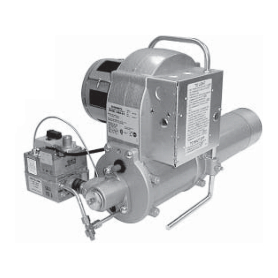
Economite 400B-02
Conversion Burners
The ECONOMITE Models 400B-02 and 400B-02P conversion burners
are adaptable to most common central gas utilization equipment,
including up-draft gravity and forced circulation furnaces and
boilers. Power burner design makes it perfectly suited for oil burner
replacement. For horizontal and downdraft gas utilization equipment,
ECONOMITE Model 400B-02 conversion burner with direct spark
ignition is recommended.
WARNING: If the information in these instructions
is not followed exactly, a fi re or explosion may result,
causing property damage, personal injury or death.
Do not store or use gasoline or other fl ammable vapors and
liquids in the vicinity of this or any other appliance.
WHAT TO DO IF YOU SMELL GAS:
•
Do not try to light any appliance.
•
Do not touch any electrical switch; do not use any
phone in your building.
•
Immediately phone your gas supplier from another
building. Follow the gas supplier's instructions. If
you cannot reach your gas supplier call the fi re
department.
Installation and service must be performed by a qualifi ed
installer, service agency or the gas supplier.
BURNER MODEL:
___________________________________
BILL OF MATERIAL
NUMBER:
___________________________________
SERIAL NUMBER #: ___________________________________
WIRING DIAGRAM: ___________________________________
FOR SERVICE CONTACT
Name:
____________________________________________
Address: ____________________________________________
____________________________________________
Phone:
____________________________________________
Date of Installation: ___________________________________
514
8470 75
Printed in USA
Advertisement

Related Manuals for Midco Economite 400B-02 Series


Summary of Contents for Midco Economite 400B-02 Series
- Page 1 • WARNING: Additions, changes, conversions and service must be performed by an authorized Midco representative, service agency or the fuel supplier. Use only MIDCO specifi ed BURNER MODEL: ___________________________________ and approved parts. BILL OF MATERIAL •...
- Page 2 Clean the gas utilization equipment, heat exchanger interior, combustion chamber, and fl ue II Preparation of the Gas connections. Remove all adhering tars, scale, dirt and soot. Inspect for actual leaks and/or potential Utilization Equipment leaks. 8470 75 Midco Inc. International...
-
Page 3: Installation
Non-standard arrangements may be available for some models; consult factory for details if required. Before permanently setting the burner in place, check venturi casting openings and pilot assembly to make sure they are free of foreign materials. See Figure 8. ____________________________________ 8470 75 Midco International Inc. - Page 4 Figure 4: Barometric Dampers and adjusted by a qualifi ed service technician in accordance with the manufacturer’s instructions. Figures 3 and 4: Copyright by the American Gas Association. Used by permission of the copyright holder. ______________________________ 8470 75 Midco Inc. International...
- Page 5 To obtain the maximum fi ring rate of 400 MBH, the NATURAL gas supply piping must be sized to provide minimum of 5.0″ W.C. pressure (11.0″ W.C. PROPANE) to the inlet of the Combination Valve when the burner and all other gas utilization equipment are on. 8470 75 Midco International Inc.
- Page 6 PROPANE) manifold gas pressure for low to minimum spud capacity input. Both models are shipped with the primary air controlling shutter set WIDE OPEN to provide a lean gas/air mixture during the initial start-up. Do not change the Combination Valve Gas Pressure Regulator setting at this time. 8470 75 Midco Inc. International...
- Page 7 If not, refer to Trouble Chart. To make a preliminary setting of the burner input, determine the manifold gas pressure required from Table 3 and adjust the Combination Valve Pressure Regulator accordingly. See Section XI. 8470 75 Midco International Inc.
- Page 8 If there is any Approximate Capacity 1000 BTU/hr serious corrosion or loss of metal at the tip replace the thermocouple. Table 4: Pilot Specifi cations Check that the pilot orifi ce diameter is correct (see Table 4). 8470 75 Midco Inc. International...
- Page 9 7 millivolts when the pilot fl ame is properly adjusted, it is defective. If the valve does not hold in with a 7 millivolts, the pilotstat is defective and entire valve must be replaced. Figure 8: Venturi Casting and Pilot Assembly 8470 75 Midco International Inc.
- Page 10 If plunger dimension is wrong, replace switch. If disk dimension is wrong, check that the actuator operates freely with a minimum movement of 1/4″ from the free position. If movement is OK, reposition blower wheel on motor shaft, if not replace wheel. ____________________________________ 8470 75 Midco Inc. International...
- Page 11 A dangerous condition has developed and must be corrected. CONTACT A QUALIFIED SERVICE TECHNICIAN FOR CLEANING READJUSTMENT AND/OR REPAIR. 8470 75 Midco International Inc.
- Page 12 Clogged pilot orifi ce(s) (See Section IX Venturi Casting and Pilot). Defective thermocouple (See Section IX Venturi Casting and Pilot). G. Defective pilotstat safety control (See Section IX Venturi Casting and Pilot). H. Clogged pilot fi lter in Combination Valve; entire valve must be replaced. 8470 75 Midco Inc. International...
-
Page 13: Trouble Chart
* Normal low voltage: Motor running-24V minimum Combination Valve energized-21V minimum. ** IMPORTANT: If changes are made in the main spud orifi ce size manifold gas pressure or primary air adjustment, change the installation data tag accordingly. 8470 75 Midco International Inc. - Page 14 Midco ® International Inc. - 4140 West Victoria Street - Chicago, Illinois 60646 - toll free: 866 705 0514 tel: 773.604.8700 - fax: 866.580.8700 - web: www.midcointernational.com - e-mail: sales@midcointernational.com 8470 75 Printed in USA...
Need help?
Do you have a question about the Economite 400B-02 Series and is the answer not in the manual?
Questions and answers