Table of Contents
Advertisement
Installation and Service Instructions
MADE
in the
USA
• In the United States, installation must conform with local codes or
in the absence of local codes, with the National Fuel Gas Code,
ANSI Z223.1-latest edition available from American National
Standard Institute. Further reference should be made to the
recommendation of your fuel supplier.
• In Canada, installation must conform with local codes or in the
absence of local codes, with Installation Codes for Gas Burning
Appliances and Equipment, CGA Standard CAN/CGA 1-B-149.1
or 2.
•
WARNING:
Additions,
and service must be performed by an authorized Midco
representative, service agency or the fuel supplier. Use only
MIDCO specifi ed and approved parts.
• INSTALLER: Inform and demonstrate to the user the correct
operation and maintenance of the gas utilization equipment.
Inform the user of the hazards of storing fl ammable liquids and
vapors in the vicinity of this gas utilization equipment and remove
such hazards. Affi x this manual and associated literature to the
burner.
CODE
COMPLIANCE
RESPONSIBILITY OF THE INSTALLER.
• USER: Retain this manual for future reference. If other than
routine service or maintenance as described in this manual
and associated literature is required, contact a qualifi ed service
agency. DO NOT ATTEMPT REPAIRS. An inadvertent service
error could result in a dangerous condition.
AVOID ERROR IN PARTS SELECTION. When ordering use complete MIDCO
Part Number and Description. Furnish Burner Model Number, Bill of Material
Number and Serial Number (if available) from the specifi cation plate found on the
product.
IMPORTANT: Availability of parts as well as specifi cations are subject to change
without notice. Please consult factory for item availability.
®
Midco
International Inc.
4140 West Victoria Street
Chicago, Illinois 60646
toll free 866.705.0514
tel
773.604.8700
fax
866.580.8700
web
www.midcointernational.com
e-mail
sales@midcointernational.com
changes,
conversions
IS
THE
SOLE
SAFETY INFORMATION TERMS: The following terms are used to identify hazards, safety precaution of special notations and
have standard meanings throughout this manual. They are printed in all capital letters using a bold type face as shown below, and
preceded by the exclamation mark symbol. When you see the safety alert symbol and one of the safety information terms as shown
below, be aware of the hazard potential.
DANGER:
Identifi es the most serious hazards which will result in severe personal injury or death.
WARNING:
Signifi es a hazard that could result in personal injury or death.
CAUTION:
Identifi es unsafe practices which would result in minor personal injury or product and property
damage.
As an ISO 9001:2008 certifi ed company, we proudly design, manufacture and assemble our products in Chicago, Illinois, USA.
Quality Designed for Proven Performance
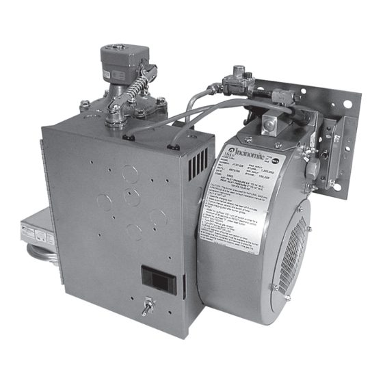
Incinomite
Model J121-DS
Gas Burner
The INCINOMITE Model J121-DS gas burner features direct main
fl ame spark ignition and solid state electronic fl ame verifi cation.
WARNING: If the information in these instructions
is not followed exactly, a fi re or explosion may result,
causing property damage, personal injury or death.
Do not store or use gasoline or other fl ammable vapors and
liquids in the vicinity of this or any other appliance.
WHAT TO DO IF YOU SMELL GAS:
•
Do not try to light any appliance.
•
Do not touch any electrical switch; do not use any
phone in your building.
•
Immediately phone your gas supplier from another
building. Follow the gas supplier's instructions. If
you cannot reach your gas supplier call the fi re
department.
Installation and service must be performed by a qualifi ed
installer, service agency or the gas supplier.
BURNER MODEL:
___________________________________
BILL OF MATERIAL
NUMBER:
___________________________________
SERIAL NUMBER #: ___________________________________
WIRING DIAGRAM: ___________________________________
FOR SERVICE CONTACT
Name:
____________________________________________
Address: ____________________________________________
____________________________________________
Phone:
____________________________________________
Date of Installation: ___________________________________
917
8471 15
Printed in USA
Advertisement
Table of Contents

Related Manuals for Midco J121-DS


Summary of Contents for Midco J121-DS
- Page 1 Gas Burner MADE in the The INCINOMITE Model J121-DS gas burner features direct main fl ame spark ignition and solid state electronic fl ame verifi cation. WARNING: If the information in these instructions is not followed exactly, a fi re or explosion may result, •...
-
Page 2: Specifications
WARNING: Under no condition should the access to outside air be so restricted that the maximum possible use of combustion air is inhibited. Pay particular attention to exhaust fans that could draw air from the area and create a negative pressure in the room __________________________________________ MADE in the 8471 15 Midco International Inc. -
Page 3: Part 1 Installation
Main Gas Port and Nozzle Support is clean and undamaged. - If the incinerator is located outdoors, the burner and all of its components, except the Main Manual Shut-Off Valve, must be protected from weather. The MIDCO Accessory Weatherhood will provide such protection. - Page 4 L1. Optional remote control devices should be connected in place of, or in addition to, the switch or timer as indicted in Figure 2A or 2B Wiring Diagram. __________________________________________ MADE in the 8471 15 Midco International Inc.
- Page 5 No.of Seconds for One Rev. Test Dial Then divide by 1,000 for MBH value. EXAMPLE: 3600 x 1 x 1000* = 180,000 BTU / Hr. = 180 MBH * Approximate BTU Value MADE in the 8471 15 Midco International Inc.
- Page 6 fl ue products from the draft control. 17. To shut off : Turn Burner Switch or Timer off and close Main Manual Shut -Off Valve MADE in the 8471 15 Midco International Inc.
- Page 7 Part 1 Installation VII Initial Start SCHEMATIC Up/Adjustment Continued LEGEND Figure 2B Wiring diagram (6455-58) Figure 3 Control Components MADE in the 8471 15 Midco International Inc.
- Page 8 SPARK TEST—Main Manual Shut-Off Valve must be off . Place the Ignitor Assembly on top of the burner with the electrode ends visible and good metal to metal contact between the Ignitor Mounting Plate and the burner chassis. MADE in the 8471 15 Midco International Inc.
-
Page 9: Blower Assembly
__________________________________________ XI Blower Assembly Model J121-DS is equipped with 1/6 HP split phase 3450 RPM motor. It may contain either a manual or auto-reset overload protector. It has no interlock, this function being performed by an Air Pressure Switch on the burner. The motor features permanently lubricated ball bearings that require no routine oiling maintenance. -
Page 10: Electronic Control System
WARNING: Explosion hazard. Do not use this device if it gets wet. It can malfunction and cause serious injury or death. Replace any device that has been wet. Figure 5 Ignitor and Flame Sensor Assembly __________________________________________ MADE in the 8471 15 Midco International Inc. -
Page 11: Trouble Chart
4″ or 5″ W.C. b. No fl ame, clean and test ignitor assembly per Section VIII IGNITOR AND REGULATOR ASSEMBLY MADE in the 8471 15 Midco International Inc. - Page 12 Incinomite - J121-DS - Installation Manual Trouble Shooting III FLAME ON ONLY DURING 6-SECOND TRIAL FOR IGNITION A. With motor running check burner line voltage terminals for 120V as follows: Continued 1. Between strip terminals L1 and L2 - 120V: voltage OK.
Need help?
Do you have a question about the J121-DS and is the answer not in the manual?
Questions and answers