Table of Contents
Advertisement
Quick Links
Instruction Manual
Form 5200
September 2004
Type 4660 High-Low Pressure Pilot
Contents
. . . . . . . . . . . . . . . . . . . . . . . . . . . . . . .
. . . . . . . . . . . . . . . . . . . . . . . . . .
. . . . . . . . . . . . . . . . . . . . . . . . . . . . . . .
. . . . . . . . . . . . . . . . . . . . . . . . . . . .
. . . . . . . . . . . . . . . . . . . . . . . . . . . . . . . .
. . . . . . . . . . . . . . . . . . . . . . . . . . . . . . . .
. . . . . . . . . . . . . . . . . . . . . . . . . .
. . . . . . . . . . . . . . . . . . . . . . . . .
. . . . . . . . . . . . . . . . . . . . . . . .
. . . . . . . . . . . . . . . . . . . . . . . . .
. . . . . . . . . . . . . . . . . . . . . . . . . . . . . . . . . . . .
. . . . . . . . . . . . . . . . . . . . . . .
. . . . . . . . . . . . . . . . . . . . . . . . . . . . . . . . .
. . . . . . . . . . . . . . . . . . . . . . . . . . . . .
. . . . . . . . . . . . . . . . . . . . . . . . . . . . .
. . . . . . . . . . . . . . . . . . . . . . . . .
. . . . . . . . . . . . . . . . . . . . . . . . .
. . . . . . . . . . . . . . . . . . . . . . . . . . . .
. . . . . . . . . . . . . . . . . . . . . . . . . . . . . . . .
. . . . . . . . . . . . . . . . . . . . . . . . . . . . . . . .
www.Fisher.com
. . . . . . . . . . . . . . . . . . . . . .
. . . . . . . . . . . . . . . . . . . . . . .
. . . . . . . . . . . . . . . . . . . . . .
. . . . . . . . . . . . . . . . . . . . .
. . . . . . . . . . . . . . . . . . . . . . .
. . .
. . . . . . . . . . . . . . . . . .
. . . . . . . . . . . . . . . . .
. . . . . . . . . . . . . . . . .
. . .
. . . . .
. . .
. . . . . . . . . . . . .
. . . . . . . . . . . . . . . . . . . . . .
. . . . . . . . .
. . . . . . . . . . . .
1
1
3
3
3
4
4
6
6
6
6
6
7
7
7
8
8
8
9
9
9
10
10
11
11
12
12
12
13
W4034/IL
13
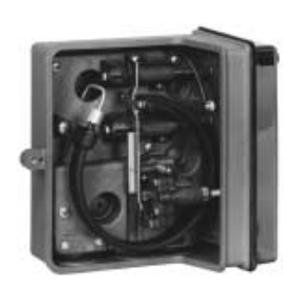
Figure 1. Type 4660 High-Low Pressure Pilot with Relay
13
Introduction
14
14
Scope of Manual
15
This instruction manual provides installation,
15
operating, maintenance, and parts ordering
16
information for the Type 4660 high-low pressure
pilot. Refer to separate instruction manuals for
information regarding the control valve actuator.
4660 Pressure Pilot
W4035/IL
FRONT VIEW
LEFT SIDE WITH
CASE COVER OFF
Advertisement
Table of Contents

Related Manuals for Emerson Fisher 4660 Pressure Pilot


Summary of Contents for Emerson Fisher 4660 Pressure Pilot
-
Page 1: Table Of Contents
Instruction Manual Form 5200 4660 Pressure Pilot September 2004 Type 4660 High-Low Pressure Pilot Contents Introduction ....... Scope of Manual . - Page 2 Instruction Manual Form 5200 4660 Pressure Pilot September 2004 Table 1. Specifications (1,4) Available Configurations Operating Conditions High-low, low-only, or high-only set point Normal Operating Nominal Condition capability Limits Reference Nitrile Elastomers: - 40 to 60_C Input Signal ( - 40 to 140_F) Type: Process pressure sensed with Bourdon Fluoroelastomer tube...
-
Page 3: Description
D carefully reading and understanding the contents of this manual. If you have any questions Emerson Process Management about these instructions, contact your Fisher sales Educational Services, Registration office. P.O. Box 190; 301 S. 1st Ave. -
Page 4: Installation
Instruction Manual Form 5200 4660 Pressure Pilot September 2004 Table 4. Maximum Allowable Process Pressure MAXIMUM ALLOWABLE EMERGENCY PROCESS PRESSURE BOURDON TUBE RATING BOURDON TUBE RATING Stainless Steel Bourdon Tubes N05500 (K-Monel) Bourdon Tubes (NACE) Psig Psig Psig 13.8 13.8 17.2 34.2 34.2... - Page 5 Instruction Manual Form 5200 4660 Pressure Pilot September 2004 PROCESS SUPPLY NO. 2 SUPPLY PROCESS NO. 1 PROCESS OUTPUT OUTPUT OUTPUT OUTPUT A. HIGH−ONLY AND LOW−ONLY PILOTS B. LOW−ONLY AND HIGH/LOW PILOTS SENSING A SINGLE PROCESS POINT WITH DUAL OUTPUTS AND DIFFERENT AND HAVING A SINGLE OUTPUT PROCESS PRESSURES 38A6084-B...
-
Page 6: Actuator Mounting
Instruction Manual Form 5200 4660 Pressure Pilot September 2004 Actuator Mounting Note For either mounting style, the process, Pilots specified for mounting on a control valve output, and supply pressure fittings actuator are normally mounted at the factory. If the may be attached to the pilot prior to pilot is ordered separately for installation on a control sliding the pilot into the cutout. -
Page 7: Process Pressure
Instruction Manual Form 5200 4660 Pressure Pilot September 2004 FRONT REMOVAL (INCH) REAR REMOVAL 18A3804-F A3299-1 / IL Figure 3. Cutout Dimensions for Panel Mounting Output Pressure Connect output pressure piping to the connection marked OUTPUT on the bottom of the pilot case as shown in figure 4. -
Page 8: Operating Information
Instruction Manual Form 5200 4660 Pressure Pilot September 2004 D Check with your process or safety to remove all flammable and hazardous gas. engineer for any additional measures that must be taken to protect against If a remote vent is required, use 19 mm (0.75 inch) process media. -
Page 9: Setting The High Set Point
Instruction Manual Form 5200 4660 Pressure Pilot September 2004 Setting the High Set Point To set the low set point pressure, perform the following three steps: Note 1. Adjust the external pressure source to the desired low set point pressure. To ensure that full output pressure will 2. -
Page 10: Pilots With Optional Set Point Indication
Instruction Manual Form 5200 4660 Pressure Pilot September 2004 Table 5. Alternate Set Point Adjustment PRESSURE PRESSURE BOURDON TUBE CHANGE CHANGE PER RATING PER DOT REVOLUTION Psig Psig Psig 17.2 34.5 69.0 1000 103.4 1500 12.4 172.4 2500 20.7 344.8 5000 41.4 517.2... -
Page 11: Prestartup Checks
Instruction Manual Form 5200 4660 Pressure Pilot September 2004 3. Push the small button in the center of the knob PERCENT OF BOURDON with a ball point pen or pencil and rotate the scale TUBE RATING CONSTRUCTION with the thumbwheel on the right hand edge of the Trip-to- Set Point Repeat-... -
Page 12: Startup
Instruction Manual Form 5200 4660 Pressure Pilot September 2004 3. Release the upper end of the flapper such that SETPOINT the flapper will snap back and contact the nozzle PIVOT PROCESS PRESSURE beam. HIGH SET POINT 4. Replace the case cover, and attach it with the PIVOT case cover screw. -
Page 13: Maintenance
Instruction Manual Form 5200 4660 Pressure Pilot September 2004 When the process pressure returns to a value Bourdon Tube/ Flapper Assembly between the low and high set points, the flapper no Replacement longer contacts one of the set point pivots, but contacts the nozzle beam, again capping off the Obtain the Bourdon tube/flapper assembly kit listed relay nozzle. -
Page 14: Low Or High Set Point Assembly Replacement
Instruction Manual Form 5200 4660 Pressure Pilot September 2004 7. Refer to the alignment of the nozzle beam 12. Loosen the set screws and remove the knob. procedure in the Operating Information section. 13. Repeat steps 1 through 12 if both set point 8. -
Page 15: Parts Ordering
Instruction Manual Form 5200 4660 Pressure Pilot September 2004 Parts Ordering Description Part Number Whenever corresponding with the Fisher sales office Bourdon Tube/Flapper Assembly about this equipment, always mention the pilot serial - - - Bourdon Tube/Flapper Assembly (Includes number located on the nameplate (key 76, figure 8) Bourdon tube/flapper and keys 18, 27, 73) on the rear of the pilot. -
Page 16: Parts List
Instruction Manual Form 5200 4660 Pressure Pilot September 2004 Description Part Number Description Part Number Low Set Point Bourdon Tube Rating O-Ring, nitrile (3 req’d) 18A1088X012 6.9 bar (100 psig) R4660XSP1J2 O-Ring, nitrile 1D2375X0022 17.2 bar (250 psig) R4660XSP1K2 Cap Screw, stainless steel (2 req’d) 34.5 bar (500 psig) R4660XSP1L2 0.25 inch NPT Female Process Connection... - Page 17 Instruction Manual Form 5200 4660 Pressure Pilot September 2004 APPLY SEALANT 48A3536-H/DOC Figure 8. Type 4660 Pilot Assembly...
- Page 18 Instruction Manual Form 5200 4660 Pressure Pilot September 2004 Key 73 Range Label Bourdon Tube Part Number Range (bar) 0-3.4 18A3534X512 0-6.9 18A3534X522 0-17.2 18A3534X532 0-34.5 18A3534X542 0-69.0 18A3534X552 0-103.4 18A3534X562 0-172.4 18A3534X572 0-344.8 18A3534X582 0-517.2 18A3534X592 0-689.5 18A3534X602 Bourdon Tube Part Number Range (Psig) 0-50...
- Page 19 Instruction Manual Form 5200 4660 Pressure Pilot September 2004...
- Page 20 Fisher is a mark owned by Fisher Controls International LLC, a member of the Emerson Process Management business division of Emerson Electric Co. The Emerson logo is a trademark and service mark of Emerson Electric Co. All other marks are the property of their respective owners.
Need help?
Do you have a question about the Fisher 4660 Pressure Pilot and is the answer not in the manual?
Questions and answers