Infineon XMC4000 Series Board User's Manual
Hide thumbs
Also See for XMC4000 Series:
- Application manual (54 pages) ,
- Device manual (38 pages) ,
- Board user's manual (35 pages)

Subscribe to Our Youtube Channel
Related Manuals for Infineon XMC4000 Series


Summary of Contents for Infineon XMC4000 Series
- Page 1 Eva lua t io n Bo ar d For XMC4000 Family X MC420 0 P lat fo r m2 G o Kit Version 1.1 Board Us er ‘s Ma nu al Revision 2019-08-30 M ic ro con tr o lle r...
- Page 2 Infineon Technologies components may be used in life-support devices or systems only with the express written approval of Infineon Technologies, if a failure of such components can reasonably be expected to cause the failure of that life-support device or system or to affect the safety or effectiveness of that device or system.
- Page 3 XMC4200 Platform2Go Series-V1 Revision History Page or Item Subjects (major changes since previous revision) Revision 2019-08- Initial Version Trademarks of Infineon Technologies AG AURIX™, C166™, CanPAK™, CIPOS™, CIPURSE™, EconoPACK™, CoolMOS™, CoolSET™, CORECONTROL™, CROSSAVE™, DAVE™, EasyPIM™, EconoBRIDGE™, EconoDUAL™, EconoPIM™, EiceDRIVER™, eupec™, FCOS™, HITFET™, HybridPACK™, I²RF™, ISOFACE™, IsoPACK™, MIPAQ™, ModSTACK™, my-d™, NovalithIC™, OptiMOS™, ORIGA™, PRIMARION™, PrimePACK™, PrimeSTACK™,...
-
Page 4: Table Of Contents
XMC4200 Platform2Go Series-V1 Table of Contents Table of Contents Introduction ..........................6 Key Features ............................7 Block Diagram ............................8 Hardware Description ....................... 8 Power Supply ............................. 11 Pin Header X1 and X2 ......................... 12 Pin Header for Microbus and Shield2Go Connector 1 and 2 ............. 13 Solderable 0 Ohm Pin Bridges ...................... - Page 5 XMC4200 Platform2Go Series-V1 Table of Contents Figure 13 ICs and Power Schematic: Can Transceiver, RTC Battery, Power ............22 Figure 14 Geometry ............................23 List of Tables Table 1 Kit Specification ........................... 6 Table 2 Kit Features of Assembly Versions ....................... 7 Table 3 Signal mapping of the 0 Ohm Pin Bridges ..................
-
Page 6: Introduction
ARM Cortex It can be used with a wide range of development tools including Infineon’s free of charge Eclipse based IDE DAVE. The XMC4200 Platform2Go Series-V1.1 are designed to evaluate the capabilities of the XMC4200 Microcontroller. Table 1 shows its specification. -
Page 7: Key Features
XMC4200 Platform2Go Series-V1 Introduction All boards are marked with “Platform2Go XMC4200-V1.1” and can be distinguished by the assembled devices (see pictures in chapter 2). These boards are neither cost nor size optimized and do not serve as a reference design. Key Features Table 2 summarizes the features of the different assembly versions of the XMC4200 Platform2Go Series-V1.1. -
Page 8: Block Diagram
Two 40-pin header X1 and X2 Connection Header for Arduino MikroBUS connector Two Infineon Shield2Go connectors (at the bottom of the board) Potentiometer (10kOhm) On-board power generation User Push-Button, User LED, Reset Push-Button ... -
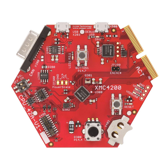
Page 9: Figure 2 Xmc4200 Platform2Go 3.3V
XMC4200 Platform2Go Series-V1 Hardware Description Figure 2 XMC4200 Platform2Go 3.3V Figure 3 XMC4200 Platform2Go 5V Board Users Manual Revision 2019-08-30... -
Page 10: Figure 4 Xmc4200 Platform2Go 3.3V Lite
XMC4200 Platform2Go Series-V1 Hardware Description Figure 4 XMC4200 Platform2Go 3.3V Lite Figure 5 XMC4200 Platform2Go 5V Lite Board Users Manual Revision 2019-08-30... -
Page 11: Power Supply
XMC4200 Platform2Go Series-V1 Hardware Description Power Supply The XMC4200 Platform2Go Series-V1.1 must be supplied by an external 5 Volt DC power supply connected to any of the micro USB plugs (X100, X101). The green Power LED (VDD3.3) indicates the presence of the generated 3.3 V supply voltage. -
Page 12: Pin Header X1 And X2
XMC4200 Platform2Go Series-V1 Hardware Description Pin Header X1 and X2 The pin headers X1 and X2 can be used to extend the evaluation board or to perform measurements on the XMC4200. Figure 7 shows the available GPIOs / signals at these pin headers. The pin table is also printed onto the bottom side of the PCB in bottom view. -
Page 13: Pin Header For Microbus And Shield2Go Connector 1 And 2
XMC4200 Platform2Go Series-V1 Hardware Description Pin Header for Microbus and Shield2Go Connector 1 and 2 The pin header for Microbus and Shield2Go Connector 1 and 2 can be used to extend the evaluation board or to perform measurements on the XMC4200. Figure 8 shows the available signals at these pin headers. The Shield2Go pin header is mounted on the bottom. -
Page 14: Solderable 0 Ohm Pin Bridges
XMC4200 Platform2Go Series-V1 Hardware Description Solderable 0 Ohm Pin Bridges The 0 Ohm (0805) pin bridges enable/disable the signal pins in Table 3 (enabled by default). To disable the signals, their resistor has to be removed. The XMC4200 pins are then usable for other usages. Table 3 Signal mapping of the 0 Ohm Pin Bridges Resistor... -
Page 15: Arduino Compatible Connector
XMC4200 Platform2Go Series-V1 Hardware Description Arduino Compatible Connector The mapping of GPIOs and XMC pin functions to Arduino compatible functions can be found in Figure 9. The Arduino compatible connector supports SPI interface (SPI_xxx) I2C interface (I2C_xxx) UART interface (UART_xxx) ... -
Page 16: User Push Buttons, Potentiometer And User Leds
XMC microcontroller families to simplify and shorten SW development. It can be downloaded at www.infineon.com/dave. The latest Segger J-Link Driver can be downloaded at http://www.segger.com/jlink-software.html. Table 6 shows the pin assignment of the XMC4200 used for debugging and UART communication. -
Page 17: Reset
The XMC4200 Platform2Go provides a CAN interface via X3, a D-Sub DE-9, and the X1 and X2 connector. Infineon’s high speed CAN transceiver (IFX1051LE) for industrial applications supports 3.3V I/O logic and is suitable for 12 V and 24 V bus systems with an excellent EMC performance. The CAN bus (signals CANH, CANL) are terminated by a 120 Ohm resistor and can provide 5V if R_opt is assembled with a 0 Ohm 0805 resistor (not assembled by default). -
Page 18: Boot Option
XMC4200 Platform2Go Series-V1 Production Data 2.12 Boot Option During power-on-reset the XMC4200 latches the signal level at the pins TMS and TCK. Based on the logic levels latched at these pins after reset the XMC4200 starts booting in different modes. TMS and TCK pins are used for debugging and by default program execution is always starting from on-chip flash (normal mode). -
Page 19: Figure 10 Connectors Schematic: Pin Header, Pin Bridges, Level Shifter, Microbus, Shield2Go
XMC4200 Platform2Go Series-V1 Production Data C301 100nF C303 100nF C302 100nF C300 100nF Figure 10 Connectors Schematic: Pin header, Pin Bridges, Level Shifter, Microbus, Shield2Go Connector, Arduino Level Jumper Board Users Manual Revision 2019-08-30... -
Page 20: Figure 11 Xmc_4200_Debug Schematic: Obd Probe
XMC4200 Platform2Go Series-V1 Production Data C130 100nF C129 100nF C128 100nF C127 10uF C126 10uF 4.7uF C125 C124 100nF C123 100nF 5 TH-Pads 2.54mm pitch Figure 11 XMC_4200_Debug Schematic: OBD Probe Board Users Manual Revision 2019-08-30... -
Page 21: Figure 12 Xmc4200 Schematic: Usb Connector, Microcontroller Pins And Power, Potentiometer Button And
XMC4200 Platform2Go Series-V1 Production Data Figure 12 XMC4200 Schematic: USB connector, Microcontroller pins and power, Potentiometer Button and LED Board Users Manual Revision 2019-08-30... - Page 22 XMC4200 Platform2Go Series-V1 Production Data C133 10uF C132 10uF Figure 13 ICs and Power Schematic: Can Transceiver, RTC Battery, Power Board Users Manual Revision 2019-08-30...
- Page 23 XMC4200 Platform2Go Series-V1 Production Data Figure 14 Geometry Board Users Manual Revision 2019-08-30...
-
Page 24: List Of Material
XMC4200 Platform2Go Series-V1 Production Data List of Material The list of material is valid for the Platform2Go XMC4200 3.3V/5V/Lite Table 10 List of Material Description Designator PackageReference Value Quantity Not fitted in* Micro Miniature BUTTON1 Pushbutton Switch P1.15, RESET FSM2JSMA Solid Tantalum Surface Mount CAPMP7343X310N-... - Page 25 XMC4200 Platform2Go Series-V1 Production Data Polymeric ESD Suppressor, 24V Medium Power AF Schottky Diode D101, D103 SOD323 BAS3010A-03W Performance of the ARM Cortex- M4 Core with Powerful On-Chip Peripheral Subsystems, Temp Range(-40°C to 125°C) IC101 PG-VQFN-48-53 XMC4200Q48K256 Voltage Regulator, 3.3 V Output IC102 PG-SOT223 IFX1117ME V33...
- Page 26 XMC4200 Platform2Go Series-V1 Production Data Surface Mount Single Turn Trimmer, Model R8 POTI 23A - J Hook P14.0 23AR10KLFTR / 10kOhm R100, R101, 0402 / 1005 Standard Thick R102, R103, Film Chip Resistor R104, R105 100R Standard Thick 0402 / 1005 Film Chip Resistor R106, R125 1MEG...
- Page 27 XMC4200 Platform2Go Series-V1 Production Data R/A - 0.318 - Male Economy D-SUB 182-009-113R561 Micro-USB 2.0 Standard, Type AB, Bottom Mount, Shell SMT X100, X101 ZX62-AB-5PA(31) THT Micro Header, 1.27mm pitch, 10 pin, vertical, double row, keying shroud , X102 FTSH-105-01-L-D-K Through hole .025'' SQ Post Header, 2.54mm...
- Page 28 . i n f i n e o n . c o m Published by Infineon Technologies AG...
Need help?
Do you have a question about the XMC4000 Series and is the answer not in the manual?
Questions and answers