Table of Contents
Advertisement
Quick Links
Advertisement
Table of Contents
Troubleshooting

Related Manuals for Rockwell Automation Allen-Bradley E3


Summary of Contents for Rockwell Automation Allen-Bradley E3
- Page 1 E3 and E3 Plus Overload Relays Bulletins 193 and 592 User Manual...
- Page 2 Reproduction of the contents of this copyrighted publication, in whole or part, without written permission of Rockwell Automation, is prohibited.
- Page 3 Throughout this manual we use notes to make you aware of safety considerations: Identifies information about practices or circumstances that can ATTENTION lead to personal injury or death, property damage or economic loss. Attention statements help you to: • identify a hazard •...
- Page 4 Low Voltage Directive This product is tested to meet Council Directive 73/23/EEC Low Voltage, by applying the following standards, in whole or in part, documented in a technical construction file: • EN 60947 Low Voltage Switchgear and Control Gear Standard...
-
Page 5: Preface
Preface Manual Objectives The purpose of this manual is to provide you with the necessary information to apply the E3 Overload Relay with DeviceNet communications. Described in this manual are methods for installing, configuring, and troubleshooting. Read this manual in its entirety before installing, IMPORTANT operating, servicing, or initializing the E3 Overload Relay. -
Page 6: Reference Manuals
If this manual is not available, please contact either the local Rockwell Automation Distributor or Sales Office and request a copy. Copies may also be ordered from the Automation Bookstore. The... -
Page 7: Table Of Contents
Table of Contents Preface Manual Objectives ........Who Should Use this Manual . - Page 8 Table of Contents Control Terminals ....... 2-14 DeviceNet Terminals......2-14 Short-Circuit Ratings .
- Page 9 Table of Contents Thermistor/PTC Protection (E3 Plus) ....3-18 PTC Trip ........3-20 PTC Warning .
- Page 10 Table of Contents Chapter 6 – Current Monitoring Parameters Introduction ........Phase Current Reporting .
- Page 11 Table of Contents Unrecoverable Error Mode ......Resetting a Trip ........Trip/Warn LED Troubleshooting Procedures .
- Page 12 Table of Contents Protection Requirements ......Overload Protection ......PTC Protection (E3 Plus) .
- Page 13 Table of Contents Figure 2.15 Full-Voltage Reversing Starter Wiring Diagram (CENELEC Nomenclature) ....2-21 Figure 2.16 Two-Speed Non-Reversing Starter Wiring Diagram (NEMA Nomenclature) ....2-22 Figure 2.17 Two-Speed Non-Reversing Starter Wiring Diagram...
- Page 14 Table of Contents Table 3.E Trip Summary ......3-26 Table 3.F Warning Summary ..... . 3-27 Table 4.A Instance 2 Data Format .
- Page 15 Table of Contents Table B.A Product Codes ......Table B.B DeviceNet Object Classes ....Table B.C Identity Object Class Attributes .
- Page 16 Table of Contents Table B.AK Parameter Group Object Instance 2 Attributes . . B-17 Table B.AL Parameter Group Object Instance 3 Attributes . . B-17 Table B.AM Parameter Group Object Instance 4 Attributes . . B-17 Table B.AN Parameter Group Object Instance 5 Attributes . . B-19 Table B.AO Parameter Group Object Instance 6 Attributes .
-
Page 17: Chapter 1 - Product Overview
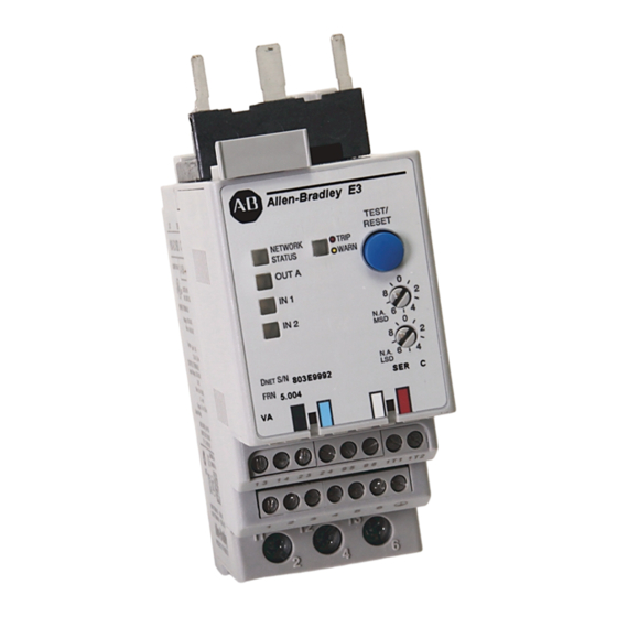
Chapter Product Overview Introduction This chapter provides a brief overview of the features and functionality of the E3 Overload Relay. Description The E3 Overload Relay is a multi-function solid-state microprocessor-based electronic overload relay for the protection of squirrel-cage induction motors rated from 1 to 2,250 Amps. -
Page 18: Catalog Number Explanation
Product Overview Catalog Number Explanation Figure 1.2 Catalog Number Explanation - EC1 Bulletin 100 Bulletin 500 Contactor Size Contactor Size Current Rating Bulletin Blank None Blank None (Amps) Number C09…C23 Size 00 C30…C43 Size 0…2 1…5 C60…C85 Size 3 3…15 5…25 Type D 9…45... -
Page 19: Current Monitoring Parameters
Product Overview Current Monitoring Parameters The E3 Overload Relay allows the user to monitor the following operational data over the DeviceNet network: • Individual phase currents (in amperes) • Individual phase currents (as a percentage of motor full-load current) • Average current (in amperes) •... -
Page 20: Inputs And Outputs
Product Overview Inputs and Outputs In addition to the trip relay, the E3 Overload Relay provides inputs and outputs according to the following table. Table 1.A E3 Overload Relay Inputs and Outputs Type Inputs Outputs E3 Plus The status of each can be monitored over the DeviceNet network through parameter 21, Device Status, or one of the input assemblies. -
Page 21: Status Indication
Product Overview Status Indication The E3 Overload Relay provides the following LED indicators: NETWORK TRIP / WARN STATUS OUT B OUT A IN 3 IN 1 IN 4 IN 2 NETWORK STATUS: This green/red LED indicates the status of the network connection. -
Page 22: Test/Reset Button
Product Overview Test/Reset Button The Test/Reset button located on the front of the E3 Overload Relay allows the user to perform the following: Test: The trip relay contact will open if the E3 Overload Relay is in an un-tripped condition and the Test/Reset button is pressed. Reset: The trip relay contact will close if the E3 Overload Relay is in a tripped condition, the cause of the trip is no longer present, and the Test/ Reset button is pressed. -
Page 23: Chapter 2 - Installation And Wiring
Chapter Installation and Wiring Introduction This chapter provides instructions for receiving, unpacking, inspecting, and storing the E3 Overload Relay. Installation and wiring instructions for common applications are also included. Receiving It is the responsibility of the user to thoroughly inspect the equipment before accepting the shipment from the freight company. -
Page 24: General Precautions
Installation and Wiring General Precautions In addition to the specific precautions listed throughout this manual, the following general statements must be observed. The E3 Overload Relay contains ESD (electrostatic ATTENTION discharge) -sensitive parts and assemblies. Static control precautions are required when installing, testing, servicing, or repairing this assembly. - Page 25 The National Electrical Code and any other governing regional or local code will overrule this information. Rockwell Automation cannot assume responsibility for the compliance or proper installation of the E3 Overload Relay or associated equipment. A hazard of personal injury and/or equipment damage exists if codes are ignored during installation.
-
Page 26: Starter Installation
Installation and Wiring Starter Installation The following figures and tables illustrate the starter assembly instructions, and Bulletin 109 and Bulletin 509 Starter approximate dimensions. Starter Assembly Instructions Figure 2.1 100-C09…C43 Starter Assembly Instructions (for use with Cat. Nos. 193-EC_B and 193-EC_D) 2.5 Nm 22 lb-in CLICK... -
Page 27: Figure 2.2 100-C60
Installation and Wiring Figure 2.2 100-C60…C85 Starter Assembly Instructions (for use with Cat. No. 193-EC_E) 4 Nm 35 lb-in Publication 193-UM001B-US-P - February 2000... -
Page 28: Starter Approximate Dimensions
Installation and Wiring Starter Approximate Dimensions Approximate dimensions are shown in milimeters (inches). Dimensions are not intended to be used for manufacturing purposes. Figure 2.3 Bulletin 109 Approximate Starter Dimensions ø Table 2.A Bulletin 109 Approximate Starter Dimensions Overload Contactor Width Height Depth... -
Page 29: Figure 2.4 Bulletin 509 Approximate Starter Dimensions
Installation and Wiring Figure 2.4 Bulletin 509 Approximate Starter Dimensions Size 00 ø Size 0...3 ø Publication 193-UM001B-US-P - February 2000... -
Page 30: Table 2.B Bulletin 509 Approximate Starter Dimensions
Installation and Wiring Table 2.B Bulletin 509 Approximate Starter Dimensions Overload NEMA Width Height Depth Cat. No. Contactor Ø Size 592-EC_T Size 00 188.3 11.4 97.9 (1-25/32) (7-13/32) (4-7/32) (1-3/8) (2-23/64) (11/64) (29/64) (3-27/32) 592-EC_C Size 0,1 90.4 248.3 112.1 69.9 243.4 5.15... -
Page 31: Panel Mount Adapter Installation
Installation and Wiring Panel Mount Adapter Installation The following figures and tables illustrate the E3 Overload Relay panel mount adapter assembly instructions and dimensions. Panel Mount Adapter Assembly Instructions Figure 2.5 193-ECPM1 and 193-ECPM2 Panel Mount Adapter Assembly Instructions (for use with Cat. Nos. 193-EC_B and 193-EC_D, respectively) CLICK Publication 193-UM001B-US-P - February 2000... -
Page 32: Figure 2.6 193-Ecpm3 Panel Mount Adapter Assembly Instructions
2-10 Installation and Wiring Figure 2.6 193-ECPM3 Panel Mount Adapter Assembly Instructions (for use with Cat. No. 193-EC_E) CLICK Publication 193-UM001B-US-P - February 2000... -
Page 33: Panel Mount Adapter Approximate Dimensions
Installation and Wiring 2-11 Panel Mount Adapter Approximate Dimensions Approximate dimensions are shown in milimeters (inches). Dimensions are not intended to be used for manufacturing purposes. Figure 2.7 193-ECPM1 Panel Mount Adapter Approximate Dimensions (for use with Cat. No. 193-EC_B) (1 - 25/32) (9/32) 159.3... -
Page 34: Figure 2.8 193-Ecpm2 Panel Mount Adapter Approximate Dimensions
2-12 Installation and Wiring Figure 2.8 193-ECPM2 Panel Mount Adapter Approximate Dimensions (for use with Cat. No. 193-EC_D) (1 - 25/32) (9/32) 154.2 (5 -5/16) (6 - 5/64) ø (11/64) 11.4 (29/64) (4-17/32) (1 - 3/16) Figure 2.9 193-ECPM3 Panel Mount Adapter Approximate Dimensions (for use with Cat. -
Page 35: Wire Size And Torque Specifications
Installation and Wiring 2-13 Wire Size and Torque Specifications Power Terminals Table 2.C Power Terminal Wire Size and Torque Specification Cat. No. 193-EC_B, 193-EC_D, 193-EC_E, 592-EC_D 592-EC_T, 592-EC_C Stranded/Solid Single Conductor 14...6 AWG 12...2 AWG Torque 22 lb-in 35 lb-in Multiple Conductor 10...6 AWG 10...2 AWG... -
Page 36: Terminal Designations
2-14 Installation and Wiring Terminal Designations Control Terminals The following table defines the E3 Overload Relay control terminal designations. Table 2.E Control Terminal Designation Terminal Reference Description Designation IN 1 General-purpose sinking input number 1 IN 2 General-purpose sinking input number 2 IN 3 General-purpose sinking input number 3 IN 4... -
Page 37: Short-Circuit Ratings
Installation and Wiring 2-15 Short-Circuit Ratings The E3 Overload Relay is suitable for use on circuits capable of delivering not more than the RMS symmetrical amperes listed in the following tables. Table 2.G UL Short-Circuit Ratings Cat. No. Maximum Available Fault Maximum Voltage Current [A] 193-EC_B, 592-EC_T... -
Page 38: Fuse Coordination
2-16 Installation and Wiring Fuse Coordination The following table illustrates the Type I and Type II fuse coordination when used in conjunction with Bulletin 100 IEC and Bulletin 500 NEMA contactors. Table 2.I Type I and Type II Fuse Coordination with 100-C Contactors Overload Contactor Low Fault... -
Page 39: Typical Motor Connections
Installation and Wiring 2-17 Typical Motor Connections Three-Phase Full-Voltage The following figure illustrates the E3 Overload Relay typical motor connections in a three-phase full-voltage application. Figure 2.10 Three-Phase Full-Voltage Wiring Diagram S.C.P.D. E3 / E3 Plus 2/T1 4/T2 6/T3 Publication 193-UM001B-US-P - February 2000... -
Page 40: Single-Phase Full-Voltage
2-18 Installation and Wiring Single-Phase Full-Voltage The following figure illustrates the E3 Overload Relay Typical motor connections in a single-phase full voltage application. Figure 2.11 Single-Phase Full-Voltage Wiring Diagram S.C.P.D. E3 / E3 Plus 2/T1 4/T2 6/T3 Parameter 27, Single/Three Ph, should be set to the IMPORTANT single-phase. -
Page 41: Typical Control Circuit Wiring Diagrams
Installation and Wiring 2-19 Typical Control Circuit Wiring Diagrams The ratings of the E3 Overload Relay’s output and ATTENTION trip relay must not be exceeded. If the coil current or voltage of the contactor exceeds the relays’ ratings, an interposing relay must be used. When the power is applied to the E3 Overload ATTENTION Relay (DeviceNet terminals V+ and V-), the N.O. -
Page 42: Full-Voltage Non-Reversing (With Network Control)
2-20 Installation and Wiring Full-Voltage Non-Reversing (with Network Control) Figure 2.12 Full-Voltage Non-Reversing Starter Wiring Diagram (NEMA Nomenclature) Out A Trip Relay (1) (1) Contact shown with supply voltage applied. Figure 2.13 Full-Voltage Non-Reversing Starter Wiring Diagram (CENELEC Nomenclature) Out A Trip Relay (1) (1) Contact shown with supply voltage applied. -
Page 43: Full Voltage Reversing (With Network Control)
Installation and Wiring 2-21 Full Voltage Reversing (with Network Control) Figure 2.14 Full-Voltage Reversing Starter Wiring Diagram (NEMA Nomenclature) E 3 P l u s E 3 P l u s O u t A Trip Relay (1) R E V F O R E 3 P l u s O u t B... -
Page 44: Two-Speed Non-Reversing (With Network Control)
2-22 Installation and Wiring Two-Speed Non-Reversing (with Network Control) Figure 2.16 Two-Speed Non-Reversing Starter Wiring Diagram (NEMA Nomenclature) E3 (low) E3 (low) E3 (high) Out A Trip Relay (1) Trip Relay (1) HIGH L O W E3 (high) Out A L O W HIGH (1) Contact shown with supply voltage applied. -
Page 45: Chapter 3 - Protective Trip And Warning Functions
Chapter Protective Trip and Warning Functions Introduction The purpose of this chapter is to provide detailed information regarding the protective trip and warning functions of the E3 Overload Relay. In this chapter, you will find considerable mention given to programming parameters as they relate to these functions. -
Page 46: Overload Protection
Protective Trip and Warning Functions Overload Protection The E3 Overload Relay provides overload protection through true RMS current measurement of the individual phase currents of the connected motor. Based on the maximum current measured and the programmed FLA Setting and Trip Class, a thermal model that simulates the actual heating of the motor is calculated. -
Page 47: Trip Class
Protective Trip and Warning Functions FLA Setting Instructions (USA and Canada): ≥ ≥ ≥ ≥ Motor Service Factor 1.15: For motors with a service factor rating of 1.15 or greater, program the FLA setting to the printed nameplate’s full-load current rating. <... -
Page 48: Time-Current Characteristics For Trip Classes
Protective Trip and Warning Functions Figure 3.1 Time-Current Characteristics for Trip Classes 5, 10, 20, and 30 E3 & E3 Plus Overload Relay E3 & E3 Plus Overload Relay Trip Class 5 Trip Class 10 1000 1000 Cold Trip Cold Trip Hot Trip Hot Trip 100%... -
Page 49: Table 3.A Time-Current Characteristic Scaling Factors
Protective Trip and Warning Functions For trip class adjustments other than 5, 10, 20, or 30, scale the Class 10 trip time according to the following chart: Table 3.A Time-Current Characteristic Scaling Factors Trip Class Trip Class Trip Trip Class Trip Class Trip Class Trip Class... -
Page 50: Auto/Manual Reset
Protective Trip and Warning Functions Auto/Manual Reset Parameter 30, OL/PTC ResetMode, allows the user to select the reset mode for the E3 Overload Relay after an overload or thermistor (PTC) trip. If an overload trip occurs and automatic reset mode is selected, the E3 Overload Relay will automatically reset when the value stored in Parameter 9,% Therm Utilized, falls below the value stored in Parameter 31, OL Reset Level. -
Page 51: Overload Reset Times
Protective Trip and Warning Functions Figure 3.2 Overload Reset Times Overload Reset Times Trip Class 5 Trip Class 10 Trip Class 20 Trip Class 30 1000 1500 2000 2500 3000 3500 4000 4500 5000 Tim e To Rese t (seconds) Overload Reset Times Trip Class 5 Trip Class 10... -
Page 52: Overload Warning
Protective Trip and Warning Functions In explosive environment applications, Parameter ATTENTION 31, OL Reset Level, should be set as low as possible or in accordance with the motor thermal time constant. Overload Warning The E3 Overload Relay will indicate an overload warning if: •... -
Page 53: Non-Volatile Thermal Memory
Protective Trip and Warning Functions Non-Volatile Thermal Memory The E3 Overload Relay includes a non-volatile circuit to provide thermal memory. The time constant of the circuit corresponds to a trip class 30 setting. During normal operation, the thermal memory circuit is continually monitored and updated to accurately reflect the thermal utilization of the connected motor. - Page 54 3-10 Protective Trip and Warning Functions Parameter 33, PL Inhibit Time, allows the installer to inhibit a phase loss trip from occurring during the motor starting sequence. It is adjustable from 0…250 seconds. Parameter 34, PL Trip Delay, allows the installer to define the time period for which a phase loss condition must be present before a trip occurs.
-
Page 55: Ground Fault Protection (E3 Plus)
Protective Trip and Warning Functions 3-11 Table 3.C Recommended Phase Loss Trip Delay Settings for Explosive Environment Applications Trip PL Trip Trip PL Trip Trip PL Trip Trip PL Trip Class Delay Class Delay Class Delay Class Delay 13.0 10.0 13.5 10.5 14.0... - Page 56 3-12 Protective Trip and Warning Functions If the E3 Plus Overload Relay trips on a ground fault, the following will occur: • The TRIP/WARN LED will flash a red 4-blink pattern • Bit 3 in Parameter 14, Trip Status, will go to “1” •...
-
Page 57: Ground Fault Warning
Protective Trip and Warning Functions 3-13 Ground Fault Warning The E3 Plus Overload Relay will indicate a Ground Fault warning if: • No warning currently exists • Ground fault warning is enabled • GF Inhibit Time has expired • GF Current is equal to or greater than the GF Warn Level When the Ground Fault warning conditions are satisfied, the following will occur: •... - Page 58 3-14 Protective Trip and Warning Functions If the E3 Overload Relay trips on a stall, the following will occur: • The TRIP/WARN LED will flash a red 5-blink pattern • Bit 4 in Parameter 14, Trip Status, will go to “1” •...
-
Page 59: Jam Protection
Protective Trip and Warning Functions 3-15 Jam Protection Motor current greater than the motor’s nameplate rating may indicate a high overload or stall condition, such as an overloaded conveyor or jammed gear. These conditions can result in overheating of the motor and equipment damage. Rapid jam fault detection helps to minimize damage and loss of production. -
Page 60: Jam Warning
3-16 Protective Trip and Warning Functions Parameter 43, Jam Trip Level, allows the installer to define the current at which the E3 Overload Relay will trip on a jam. It is user-adjustable from 50…600% of the FLA Setting (parameter 28). The jam inhibit timer starts after the maximum phase IMPORTANT of load current transitions from 0 A to 30% of the... -
Page 61: Underload Trip
Protective Trip and Warning Functions 3-17 Underload Trip The E3 Overload Relay will trip with an underload indication if: • No trip currently exists • Underload Protection is enabled • UL Inhibit Time has expired • Minimum phase current is less than the UL Trip Level for a time period greater than the UL Trip Delay If the E3 Overload Relay trips on an underload, the following will occur: •... -
Page 62: Underload Warning
3-18 Protective Trip and Warning Functions Underload Warning The E3 Overload Relay will immediately indicate an Underload warning if: • No warning currently exists • Underload Warning is enabled • UL Inhibit Time has expired • The minimum phase current is less than the UL Warn Level When the Underload Warning conditions are satisfied, the following will occur: •... -
Page 63: Table 3.D E3 Plus Ptc Input Ratings
Protective Trip and Warning Functions 3-19 The following table defines the E3 Plus Overload Relay’s PTC thermistor input and response ratings: Table 3.D E3 Plus PTC Input Ratings Ω ± Ω Response resistance 3400 Ω ± Ω Reset resistance 1600 Ω... -
Page 64: Ptc Trip
3-20 Protective Trip and Warning Functions PTC Trip The E3 Plus Overload Relay will trip with a PTC indication if: • No trip currently exists • PTC protection is enabled • The resistance across terminals 1T1 and 1T2 is either greater than the relay’s response resistance or less than the short-circuit trip resistance If the E3 Plus Overload Relay trips on a PTC, the following will occur: •... -
Page 65: Current Imbalance Protection
Protective Trip and Warning Functions 3-21 Current Imbalance Protection A current imbalance can be caused by an unbalance in the voltage supply, unequal motor winding impedance, or long and varying wire lengths. When a current imbalance exists, the motor can experience an additional temperature rise, resulting in degradation of the motor insulation and reduction of life expectancy. -
Page 66: Current Imbalance Warning
3-22 Protective Trip and Warning Functions Parameter 50, CI Trip Delay, allows the installer to define the time period for which a current imbalance condition must be present before a trip occurs. It is adjustable from 0.1…25.0 seconds. Parameter 51, CI Trip Level, allows the installer to define the percent current imbalance which will cause the relay to trip on a Current Imbalance. -
Page 67: Communication Fault Protection
Protective Trip and Warning Functions 3-23 Communication Fault Protection A disruption of the communication link between the E3 Overload Relay and a DeviceNet network can result in the loss of application control and/or critical process diagnostic data. Rapid communication fault detection helps minimize potential damage due to uncontrolled or unmonitored applications. -
Page 68: Comm Fault Warning
3-24 Protective Trip and Warning Functions Comm Fault Warning The E3 Overload Relay will indicate a Comm Fault warning if: • No warning currently exists • Comm Fault Warning is enabled • The relay experiences a loss of communication When the Comm Fault warning conditions are satisfied, the following will occur: •... -
Page 69: Comm Idle Warning
Protective Trip and Warning Functions 3-25 If the relay trips on a Comm Idle, the following will occur: • The TRIP/WARN LED will flash a red 11-blink pattern • Bit 10 in Parameter 14, Trip Status, will go to “1” •... -
Page 70: Protective Trip And Warning Summary
3-26 Protective Trip and Warning Functions Protective Trip and Warning Summary Table 3.E Trip Summary Trip Trip Trip Level Settings Trip Delay Settings Inhibit Time Function Enable Settings Factory Range Default Range Default Range Default Default Overload Enabled Trip Class Trip Class —... - Page 71 Protective Trip and Warning Functions 3-27 Table 3.F Warning Summary Warning Warning Warning Level Settings Inhibit Time Settings Function Enable Range Default Range Default Factory Default Overload Disabled 0…100% — — Phase Loss — — — — — Ground Fault Disabled 1.0…5.0 A 2.0 A...
-
Page 72: Chapter 4 - Devicenet Node Commissioning
Chapter DeviceNet Node Commissioning Introduction The purpose of this chapter is to provide an overview of the steps necessary to commission the E3 Overload Relay with a DeviceNet scanner. This chapter describes how to: • Setup the E3 Overload Relay on a DeviceNet network •... -
Page 73: Single Pass Browse
DeviceNet Node Commissioning Single Pass Browse After invoking RSNetWorx, perform a “Single Pass Browse.” A “Single Pass Browse” identifies all of the nodes that are on the network. Following are steps in performing this activity. 1. From the “Network” menu, choose “Single Pass Browse.” 2. -
Page 74: Building And Registering An Eds File
DeviceNet Node Commissioning up as an “Unregistered Device” in the RSNetWorx window, as shown in the next figure. For versions later than 2.11.51, the E3 Overload Relay EDS files and icon are included with the release. If the E3 Overload Relay does not show up as an “Unregistered Device”... - Page 75 DeviceNet Node Commissioning 1. RIGHT mouse click on the “Unrecognized Device” icon. A menu like the one shown below will appear. Choose “Register Device” from the menu. The following screen appears: Publication 193-UM001B-US-P - February 2000...
- Page 76 DeviceNet Node Commissioning 2. Click Next. The following screen appears: 3. Choose the “Upload EDS” radio button as shown above and then click Next>. The following screen appears: Once the Wizard has verified support for parameter uploading, the following screen appears: Publication 193-UM001B-US-P - February 2000...
- Page 77 DeviceNet Node Commissioning 4. Click Next >. The following screen appears: 5. The E3 Overload Relay supports Polled I/O and Change of State (COS)/ Cyclic I/O messaging, so check them as shown in the example above. Then click Next >. The following screen appears: 6.
- Page 78 DeviceNet Node Commissioning screen appears: 7. At this point, you may choose to change the icon associated with the device. (This is not required, but an E3 Overload Relay icon is available.) To change the icon, click Change icon..The following screen appears: Publication 193-UM001B-US-P - February 2000...
- Page 79 DeviceNet Node Commissioning 8. Click Browse... to locate the icon file for the E3 Overload Relay. The standard file open dialog will appear. 9. Choose the icon file and click Open. The following screen appears: Publication 193-UM001B-US-P - February 2000...
- Page 80 DeviceNet Node Commissioning 10. Click OK. The Wizard screen will appear as follows: 11. Click Next >. The following screen appears: Publication 193-UM001B-US-P - February 2000...
- Page 81 DeviceNet Node Commissioning 4-10 12. Click Finish. The RSNetWorx screen will be updated as follows: Publication 193-UM001B-US-P - February 2000...
-
Page 82: Changing The Node Address (Mac Id)
4-11 DeviceNet Node Commissioning Changing the Node Address (MAC ID) Every device on a DeviceNet network must have a unique MAC ID between 0 and 63. All E3 Overload Relays are shipped from the factory with the MAC ID set to 63. The following steps illustrate how to modify the MAC ID. - Page 83 DeviceNet Node Commissioning 4-12 2. Clicking on Browse... will prompt a screen similar to the one below to appear: 3. Click the E3 Overload Relay icon to select it, and then click OK. The Node Commissioning screen will have the “Current Device Settings” entries filled in as shown below.
- Page 84 4-13 DeviceNet Node Commissioning 4. Enter the desired Node Address in the “New Device Settings” section. In this example, the new node address 4 has been selected. Click Apply to apply the new node address. When the new Node Address has been successfully applied, the “Current Device Settings”...
-
Page 85: Device Parameter Programming - Input And Output Assemblies
DeviceNet Node Commissioning 4-14 Device Parameter Programming — Input and Output Assemblies The terms “input” and “output” are defined from the programmable controller/ DeviceNet scanner point-of-reference. Output assemblies are defined as the information that is “output” by the programmable controller/DeviceNet scanner and “consumed”... - Page 86 4-15 DeviceNet Node Commissioning Table 4.C Instance 103 Data Format (Similar to Basic Motor Starter Output Assembly in ODVA Motor Starter Profile) Byte Bit 7 Bit 6 Bit 5 Bit 4 Bit3 Bit 2 Bit 1 Bit 0 Fault Reset OutA Setting Parameter 59, Output Assembly, to the value “104”...
- Page 87 DeviceNet Node Commissioning 4-16 Setting Parameter 60, Input Assembly, to the value “51” chooses Input Assembly instance 51 which has the following data format. This Input Assembly may be used with E3 and E3 Plus devices. Table 4.G Instance 51 Data Format (Extended Overload Input Assembly from ODVA Overload Profile) Byte Bit 7...
- Page 88 4-17 DeviceNet Node Commissioning Table 4.J Instance 100 Attributes (Parameter Based Input Assembly) Byte Word Value Value of parameter pointed to by param #63 (Low Byte) Value of parameter pointed to by param #63 (High Byte) Value of parameter pointed to by param #64 (Low Byte) Value of parameter pointed to by param #64 (High Byte) Publication 193-UM001B-US-P - February 2000...
- Page 89 DeviceNet Node Commissioning 4-18 The following steps illustrate how to modify the assembly assignments while using RSNetWorx in the “on-line” mode. 1. To enter the “on-line” mode, choose “on-line” from the “Network” menu. The following dialog box appears: 2. Click OK to close the dialog box. 3.
- Page 90 4-19 DeviceNet Node Commissioning 5. Click Upload. This will upload all of the current parameter values from the E3 Overload Relay for display. The following screen appears: 6. Under the “Groups” heading, select the “DNet Setup” group of parameters as shown below: Publication 193-UM001B-US-P - February 2000...
- Page 91 DeviceNet Node Commissioning 4-20 7. The settings for Parameters 59 and 60 can be modified in the “Current Value” column. Editing is accomplished in spreadsheet-like fashion. It will be helpful when you set up the scanner’s IMPORTANT scanlist in the next section to record the size (in bytes) of the input and output assemblies selected.
-
Page 92: Mapping To The Scanner's Scanlist
4-21 DeviceNet Node Commissioning Mapping to the Scanner’s Scanlist 1. Double-clicking on the “1747-SDN Scanner Module” icon in the “RSNetWorx for DeviceNet” window, the following window appears: 2. Click on the “Module” tab. The following screen will appear. Verify that the “Interscan Delay”... - Page 93 DeviceNet Node Commissioning 4-22 3. Clicking on the “Scanlist” tab, the following window appears: Publication 193-UM001B-US-P - February 2000...
- Page 94 4-23 DeviceNet Node Commissioning 4. Click Upload. This will upload all of the scanner configuration data to RSNetWorx. When the upload is complete, the following screen appears: 5. Select the device to be mapped (in this case, select the “04, E3 Plus (1 - 5A) (3)”...
- Page 95 DeviceNet Node Commissioning 4-24 6. Edit the I/O data by either clicking on the E3 Overload Relay in the “Scanlist” box and then clicking Edit I/O Parameters..., or by double-clicking on the E3 Overload Relay in the “Scanlist” box. The following screen appears: To set up a polled I/O connection, enter the following fields: Table 4.K Polled I/O Parameter Descriptions...
- Page 96 4-25 DeviceNet Node Commissioning “Change of State” messages are produced by the E3 Overload Relay when a change in the state of conditions enabled in Parameters 58, COS Mask, occur. Function: X Trip Warning Output A Output B (E3 Plus) Input 1 Input 2 Input 3 (E3 Plus)
-
Page 97: Input/Output Mapping In The Scanlist
DeviceNet Node Commissioning 4-26 Input/Output Mapping in the Scanlist 1. Click on the “Input” tab in the 1747-SDN Scanner Module window. The simplest way to map the input data is to click AutoMap. RSNetWorx will map the inputs to the discrete area of the SLC 500. Once mapped, the screen appears as follows: 2. - Page 98 4-27 DeviceNet Node Commissioning screen will appear as follows: 3. The Scanlist definition and data mapping are now complete. Click Apply. The following window appears: 4. Click Yes to initiate the downloading of the Scanlist and data mapping to the scanner.
-
Page 99: Chapter 5 - Programmable Parameters
Chapter Programmable Parameters Introduction This chapter describes each programmable parameter and its function. Parameter Programming Refer to Chapter 4 — DeviceNet Node Commissioning for instructions in using RSNetworx for DeviceNet to modify parameter settings. The section, Device Parameter Programming — Input and Output Assemblies, shows an example of modifying Parameters 59 and 60. -
Page 100: Parameter Group Listing
Programmable Parameters Parameter Group Listing The E3 Overload Relay contains six parameter groups. The parameters shown in the Overload Setup, Advanced Setup, DeviceNet Setup, Output Setup, and Reset/ Lock groups will be discussed in this chapter. The parameters in the Monitor group will be discussed in Chapter 6 —... -
Page 101: Overload Setup Group
Programmable Parameters Overload Setup Group SINGLE/THREE PH Parameter Number Access Rule Get/Set This parameter allows the installer to configure Data Type BOOL the E3 for single-phase or three-phase mode. When set to single-phase mode, the E3 will Object Mapping -1-127 report L3 Current = 0A, report L3%FLA = 0%, and only use L1 Current and L2 Current to Group... - Page 102 Programmable Parameters Table 5.B FLA Setting Ranges and Default Values (with indicated setting precision) FLA Current Range (A) Default Value 1.00 5.00 1.00 3.00 15.00 3.00 5.00 25.00 5.00 45.0 18.0 90.0 18.0 28.0 140.0 28.0 42.0 210.0 42.0 60.0 302.0 60.0 1215...
- Page 103 Programmable Parameters OL/PTC RESET MODE Parameter Number Access Rule Get/Set This parameter defines whether an Overload or PTC Trip can be automatically or manually Data Type BOOL reset. Note: all other trips must be manually Object Mapping 0x29-1-130 reset. Group Basic Overload Setup Units Minimum Value...
-
Page 104: Advanced Setup Group
Programmable Parameters Advanced Setup Group TRIP ENABLE Parameter Number Access Rule Get/Set This parameter allows the installer to enable or disable trip functions separately. Overload, Data Type WORD Phase Loss, and Comm Fault are enabled from Object Mapping 0x29-1-124 the factory. Group Advanced Setup 1 = Enabled... - Page 105 Programmable Parameters WARNING ENABLE Parameter Number Access Rule Get/Set This parameter allows the installer to enable or disable warning functions separately. All Data Type WORD warning functions are disabled from the Object Mapping 0x29-1-125 factory. Group Advanced Setup 1 = Enabled Units 0 = Disabled Minimum Value...
- Page 106 Programmable Parameters PL INHIBIT TIME Parameter Number Access Rule Get/Set This parameter defines the amount of time that phase loss detection is inhibited during a motor Data Type USINT starting sequence. Object Mapping -1-133 Group Advanced Setup Units Seconds Minimum Value Maximum Value Default Value PL TRIP DELAY...
- Page 107 Programmable Parameters GF TRIP LEVEL (E3 PLUS) Parameter Number Access Rule Get/Set This parameter sets the ground fault trip level. Data Type USINT Object Mapping 0xB4-1-1 (E3) -1-137 (E3 Plus) Group Advanced Setup Units Amps Minimum Value Maximum Value Default Value GF WARN LEVEL (E3 PLUS) Parameter Number Access Rule...
- Page 108 5-10 Programmable Parameters JAM INHIBIT TIME Parameter Number Access Rule Get/Set This parameter defines the amount of time jam detection is inhibited during a motor starting Data Type USINT sequence. Object Mapping -1-141 Group Advanced Setup Units Seconds Minimum Value Maximum Value Default Value JAM TRIP DELAY...
- Page 109 Programmable Parameters 5-11 UL INHIBIT TIME Parameter Number Access Rule Get/Set This parameter defines the amount of time underload detection is inhibited during a motor Data Type USINT starting sequence. Object Mapping -1-145 Group Advanced Setup Units Seconds Minimum Value Maximum Value Default Value UL TRIP DELAY...
- Page 110 5-12 Programmable Parameters CI INHIBIT TIME Parameter Number Access Rule Get/Set This parameter defines the amount of time current imbalance detection is inhibited during Data Type USINT a motor starting sequence. Object Mapping -1-149 Group Advanced Setup Units Seconds Minimum Value Maximum Value Default Value CI TRIP DELAY...
-
Page 111: Reset/Lock Group
Programmable Parameters 5-13 Reset/Lock Group TRIP RESET Parameter Number Access Rule Get/Set This parameter provides the user with the capability of resetting a trip over the DeviceNet Data Type BOOL network. After a trip is reset, the parameter Object Mapping 0x29-1-126 automatically returns to a “Ready”... -
Page 112: Devicenet Setup Group
5-14 Programmable Parameters DeviceNet Setup Group AUTO BAUD ENABLE Parameter Number Access Rule Get/Set When this parameter is enabled, the device will attempt to determine the network baud Data Type BOOL rate and set its baud rate to the same, provided Object Mapping 0xB4-1-15 network traffic exists. - Page 113 Programmable Parameters 5-15 COS MASK Parameter Number Access Rule Get/Set This parameter allows the installer to define the change-of-state conditions that will result Data Type WORD in a change-of-state message being produced. Object Mapping 0xB4-1-13 1 = Enabled Group DeviceNet Setup 0 = Disabled Units Minimum Value...
- Page 114 5-16 Programmable Parameters ASSY WORD 0 PARAM Parameter Number Access Rule Get/Set This parameter assigns the parameter value to be placed in Word 0 of Input Assembly 100. Data Type USINT Object Mapping 0xB4-1-7 Group DeviceNet Setup Units Minimum Value Maximum Value Default Value ASSY WORD1 PARAM...
-
Page 115: Output Setup Group
Programmable Parameters 5-17 Output Setup Group The parameters in the Output Setup Group provide IMPORTANT great flexibility in terms of output relay(s) operation under the conditions of Protection Faults, Comm Fault, and Comm Idle. It is important, therefore, that the installer fully understands the use of these parameters, their interaction with Parameter 24, Trip Enable, and the order of priority. - Page 116 5-18 Programmable Parameters OUTA PR FLTSTATE Parameter Number Access Rule Get/Set This parameter in conjunction with Parameter 66 defines how Output A will respond when a Data Type BOOL trip occurs. When set to “1”, Output A will Object Mapping 0x09-1-113 continue to operate as commanded via the Group...
- Page 117 Programmable Parameters 5-19 OUTA DN IDLSTATE Parameter Number Access Rule Get/Set This parameter in conjunction with Parameter 70 defines how Output A will respond when the Data Type BOOL DeviceNet network is idle. When set to “1”, Object Mapping 0x09-1-7 Output A will hold the state prior to trip Group DeviceNet I/O...
- Page 118 5-20 Programmable Parameters OUTB DN FLTSTATE (E3 PLUS) Parameter Number Access Rule Get/Set This parameter in conjunction with Parameter 74 defines how Output B will respond when a Data Type BOOL DeviceNet network fault occurs. When set to Object Mapping 0xB4-1-1 (E3) “1”, Output B will hold the state prior to trip 0x09-2-5 (E3 Plus)
-
Page 119: Chapter 6 - Current Monitoring Parameters
Chapter Current Monitoring Parameters Introduction This chapter provides information for the current monitoring parameters of the E3 Overload Relay. Phase Current Reporting Current Range The E3 Overload Relay utilizes a true RMS algorithm to calculate the RMS value of the current passing through phase L1, L2, and L3. The relay is capable of sensing and reporting currents ranging from 0% to 720% of the maximum FLA Setting. -
Page 120: Frequency Range
Current Monitoring Parameters The chart below illustrates the reporting current precision, the minimum and maximum reporting current values, and the 720% maximum FLA value for each current range. Table 6.A Current Reporting Summary (with indicated precision) Current Range Min Reporting Max Reporting 720% Max FLA Current... -
Page 121: Reporting Accuracy
Current Monitoring Parameters Reporting Accuracy ± The current range accuracy of the E3 Overload Relay is 5% when the operating current is between 100% of the minimum and 720% of the maximum FLA value, ± 10% when operating between 50% and 100% of the minimum FLA value. The accuracy specified above is only applicable to IMPORTANT non-distorted sinusoidal currents. -
Page 122: Monitor Group
Current Monitoring Parameters Monitor Group L1 CURRENT Parameter Number Access Rule This parameter provides the L1 phase current measurement in amperes. Data Type Object Mapping -1-231 -1-8 -1-227 Group Monitor Units Amps Minimum Value See table Maximum Value See table Default Value None L2 CURRENT... - Page 123 Current Monitoring Parameters AVERAGE CURRENT Parameter Number Access Rule This parameter provides the average current measurement in amperes. Data Type Object Mapping -1-230 -1-5 -1-226 Group Monitor Units Amps Minimum Value See table Maximum Value See table Default Value None L1 %FLA Parameter Number Access Rule...
- Page 124 Current Monitoring Parameters AVERAGE %FLA Parameter Number Access Rule This parameter provides the average current measurement as a percentage of the motor’s Data Type UINT full load current rating (Parameter 28, FLA Object Mapping -1-108 Setting). Group Monitor Units % FLA Minimum Value Maximum Value 1000...
-
Page 125: Chapter 7 - Diagnostic Parameters
Chapter Diagnostic Parameters Introduction This chapter provides an overview of the diagnostic and status parameters reported by the E3 Overload Relay. Monitor Group TIME TO TRIP Parameter Number Access Rule This parameter provides an estimated time for an overload trip to occur when the measured Data Type UINT motor current exceeds the trip rating. - Page 126 Diagnostic Parameters TRIP STATUS Parameter Number Access Rule This parameter provides trip identification. Data Type WORD 1 = Trip Object Mapping 0x29-1-114 0 = No Trip Group Monitor Units Minimum Value Maximum Value Default Value None Function: 15 14 13 12 11 10 X Test Trip Overload Phase Loss...
- Page 127 Diagnostic Parameters WARNING STATUS Parameter Number Access Rule This parameter provides warning identification. Data Type WORD Object Mapping 0x29-1-115 Group Monitor Units Minimum Value Maximum Value Default Value None Function: 15 14 13 12 11 10 Overload Ground Fault (E3 Plus) Underload PTC (E3 Plus) Current Imbalance...
- Page 128 Diagnostic Parameters TRIP LOG 2 Parameter Number Access Rule This parameter records the trip previous to Trip Log 1. Data Type WORD Object Mapping 0x29-1-118 Group Monitor Units Minimum Value See Trip Status table Maximum Value See Trip Status table Default Value None TRIP LOG 3...
- Page 129 Diagnostic Parameters DEVICE STATUS Parameter Number Access Rule This parameter provides status information of the E3 Overload Relay as outlined in the table Data Type WORD below. Object Mapping 0x29-1-121 1 = On or Present Group Monitor 0 = Off or Not Present Units Minimum Value Maximum Value...
-
Page 130: Chapter 8 - Logic Controller Application Example With Explicit Messaging
Chapter Logic Controller Application Example with Explicit Messaging Introduction This example demonstrates discrete control of the E3 Overload Relay’s output relay in addition to use of the explicit messaging function for transferring parameter data to an SLC500 via the 1747-SDN DeviceNet scanner module. Many of the selections shown are example-specific. - Page 131 Logic Controller Application Example with Explicit Messaging Table 8.A Input Addresses Bit Description Address Trip (Device Status) I: 1.16 Table 8.B Output Addresses Bit Description Address OUT A O: 1.16 Fault Reset O: 1.18 Explicit Messaging The 1747-SDN scanner module uses the M0 and M1 file areas for data transfer. Words 224 through 256 MUST be used to execute the Explicit Message Request and Response functions.
- Page 132 Logic Controller Application Example with Explicit Messaging Table 8.D Explicit Message Response (Get_Atribute_Single) TXID STATUS word 0 PORT SIZE SERVICE MAC ID DATA word 3 Transmission ID (TXID): The scanner uses this value to track the transaction to completion, and returns the value with the response that matches the request downloaded by the SLC-500 processor.
-
Page 133: Examples
Logic Controller Application Example with Explicit Messaging Examples The following table lists the most common codes for each given transaction type. Table 8.E Common Code Examples Transaction Type Service Class Instance Attribute Get_Attribute_Single 0x0E 0x0F Par. # Set_Attribute_Single 0x10 0x0F Par. -
Page 134: Get_Attribute_Single Structure
Logic Controller Application Example with Explicit Messaging Figure 8.2 Get_Attribute_Single Structure TXID Command Port Size Service MAC ID Class Instance Attribute File N10:0 01 01 00 06 0E 04 000F 0010 0001 Publication 193-UM001B-US-P - February 2000... -
Page 135: Figure
Logic Controller Application Example with Explicit Messaging Figure 8.3 Example Ladder Logic Program Rung 0: The 1747-SDN scanner module will map output data from it's scanner output table (M0) and discrete outputs to each node only when it is in the "run mode". This is accomplished by setting bit 0 of the 1747-SDN's command word (word 0). S c a n n e r R U N B i t O : 1 1 7 4 7 - S D N... -
Page 136: Chapter 9 - Troubleshooting
Chapter Troubleshooting Introduction The purpose of this chapter is to assist in troubleshooting the E3 Overload Relay using its advisory LED’s and diagnostic parameters. Servicing energized industrial control equipment ATTENTION can be hazardous. Electrical shock, burns, or unintentional actuation of controlled industrial equipment may cause death or serious injury. -
Page 137: Advisory Leds
Troubleshooting Advisory LEDs The E3 Overload Relay provides the following advisory LED indicators: NETWORK TRIP / WARN STATUS OUT A OUT B IN 1 IN 3 IN 2 IN 4 Trip/Warn LED This Trip/Warn LED will indicate device status by flashing a red trip code or an amber warning code. -
Page 138: Network Status Led
Troubleshooting The Trip conditions identified as “Protection Faults” IMPORTANT are the basis for the OUTA Pr FltState, OUTA Pr FltValue, OUTB Pr FltState, and OUTB Pr FltValue parameters. Cycling power to the E3 Overload Relay will not IMPORTANT clear a “Non-Volatile Fault”. A “Non-Volatile Fault” must be manually reset. -
Page 139: Power-Up Sequence
Troubleshooting Power-Up Sequence After the E3 Overload Relay is installed per the guidelines specified in Chapter 2, apply power to the overload relay’s DeviceNet connector. After applying power, the following sequence should occur: 1. The TRIP/WARN LED should flash red one time, and the trip relay should close 2.35 seconds after power was applied (unless a “Non-Volatile Fault”... -
Page 140: Devicenet Modes Of Operation
Troubleshooting DeviceNet Modes of Operation The E3 Overload Relay has four DeviceNet modes of operation: Power-up Reset Mode, Run Mode, Recoverable Error Mode, and Unrecoverable Error Mode. Power-Up Reset Mode During Power-Up Reset Mode, the following occurs: 1. The NETWORK STATUS LED will flash green for 1/4 second, then red for 1/4 second. -
Page 141: Recoverable Error Mode
Troubleshooting Recoverable Error Mode In Recoverable Error Mode, the E3 Overload Relay’s NETWORK STATUS LED turns solid red. The overload relays will respond to messages that are specified in offline node recovery message protocol. Error Type Description LED State Recoverable Duplicate node address detected Solid Red Unrecoverable Error Mode... -
Page 142: Resetting A Trip
Troubleshooting Resetting a Trip Resetting a trip will not correct the cause for the ATTENTION trip. Corrective action should be taken before resetting the trip. An E3 Overload Relay trip condition can be reset by taking one of the following actions: 1. -
Page 143: Trip/Warn Led Troubleshooting Procedures
Troubleshooting Trip/Warn LED Troubleshooting Procedures The following table lists the possible causes for each trip type and the recommended action to take. Table 9.B Trip/Warn LED Troubleshooting Procedures Trip Description Possible Cause Corrective Action Test Trip 1. Operation of the Test/Reset 1. - Page 144 Troubleshooting Trip/Warn LED Troubleshooting Procedures, continued Trip Description Possible Cause Corrective Action 1. Motor stator windings 1. Check for source of motor overheated overtemperature (i.e. overload, obstructed cooling, high ambient temperature, excessive starts/ hour). 2. Thermistor leads short-circuited 2. Inspect thermistor leads for or broken short-circuit or open Current Imbalance...
-
Page 145: Devicenet Troubleshooting Procedures
Troubleshooting 9-10 DeviceNet Troubleshooting Procedures The following table identifies possible causes and corrective actions when troubleshooting DeviceNet related failures using the NETWORK STATUS LED. Table 9.C DeviceNet Troubleshooting Procedures Color State Possible Cause Corrective Action None 1. The E3 Overload Relay is not 1. -
Page 146: Input And Output Troubleshooting Procedures
9-11 Troubleshooting Input and Output Troubleshooting Procedures If the outputs are to be commanded via an explicit message, ATTENTION ensure that there can never be an established I/O connection that can actively control them, and that the explicit message connection has a non-zero expected packet rate (EPR) setting. Table 9.D Input and Output Troubleshooting Procedures Failure Failure Description... - Page 147 Troubleshooting 9-12 Input and Output Troubleshooting Procedures, continued Failure Failure Description Corrective Action Type OUT A or Output A or Output B does 1. Check the supply voltage on the DeviceNet connector. OUT B not appear to turn on (close) 2.
-
Page 148: Appendix A - Specifications
Appendix Specifications Electrical Specifications Table A.A Motor/Load Ratings Terminals 1/L1, 3/L2, 5/L3, 2/T1, 4/T2, 6/T3 Rated Insulation Voltage (Ui) 690 V AC Rated Operating Voltage (Ue) IEC: 690 V AC 600 V AC Rated Impulse Voltage (Uimp) 6 kV Rated Operating Current (Ie) See Catalog Number Explanation Rated Frequency 20...250 Hz... -
Page 149: E3 & E3 Plus Power Supply Current
Specifications Figure A.1 E3 & E3 Plus Power Supply Current E3 Plus Input Volt age (V) Table A.C Output and Trip Relay Ratings Terminals OUT A: 13/14 OUT B (E3 Plus): 23/24 Trip Relay: 95/96 Type of Contacts Form A SPST - NO Rated Thermal Current (Ithe) Rated Insulation Voltage (Ui) - Page 150 Specifications Table A.D Input Ratings Terminals IN 1: IN 2: IN 3 (E3 Plus): IN 4 (E3 Plus): Supply Voltage (24V DC): Supply Voltage 24V DC ± 10% (provided by E3) Type of Inputs Current Sinking On-State Voltage 15V DC On-State Current (turn-on) 2 mA Steady State Current...
-
Page 151: Environmental Specifications
Specifications Environmental Specifications Table A.F Environmental Specifications Ambient Temperature Storage -40°C to 85°C (-40°F to 185°F) Operating (Open) -20°C to 55°C (-4°F to 131°F) (Enclosed) -20°C to 40°C (-4°F to 104°F) Humidity Operating 5% to 95% Non-condensing Damp Heat – Steady State (per IEC 68-2-3) 92% r.h., 40°C (104°F), 56 days Damp Heat –... -
Page 152: Functionality Specifications
Specifications Functionality Specifications Table A.H DeviceNet Communications Baud Rate 125k, 250k, 500k Auto-Baud Rate Identification “Group 2 – Slave Only” device type Polled I/O Messaging Change of State Messaging Cyclic Messaging Explicit Messaging Full Parameter Object Support Group 4 – Off-Line Node Recovery Messaging Configuring Consistency Value Publication 193-UM001B-US-P - February 2000... -
Page 153: Protection
Specifications Protection Table A.I Protection Trip Warning Overload Phase Loss Ground Fault (E3 Plus) Stall Underload Thermistor (PTC) (E3 Plus) Current Imbalance Communication Fault Communication Idle Table A.J Overload Protection Type of Relay Ambient Compensated Time-Delay Phase Loss Sensitive Nature of Relay Solid-State FLA Setting See Chapter 5... -
Page 154: Electronic Data Sheets
Appendix DeviceNet Information Electronic Data Sheets Electronic Data Sheet (EDS) files are specially formatted ASCII files that provide all of the information necessary for a configuration tool (e.g. RSNetWorx for DeviceNet) to access and alter the parameters of a device. The EDS file contains all the parameter information of a device: number of parameters, groupings, parameter name, min, max, and default values, units, data format and scaling. -
Page 155: Devicenet Objects
DeviceNet Information Table B.A Product Codes Product Codes Inputs Outputs Ground Current Range Fault/PTC 9.0 to 45.0 18.0 to 90.0 18.0 to 90.0 28.0 to 140.0 28.0 to 140.0 42.0 to 210.0 42.0 to 210.0 60.0 to 302.0 60.0 to 302.0 84 to 420 84 to 420 125 to 630... -
Page 156: Identity Object - Class Code 0X01
DeviceNet Information Table B.B DeviceNet Object Classes Class Object 0x08 Discrete Input Point 0x09 Discrete Output Point 0x0F Parameter 0x10 Parameter Group 0x29 Control Supervisor 0x2B Acknowledge Handler 0x2C Overload 0xB4 DN Interface Object 0xC2 PCP Object Identity Object – Class Code 0x01 The following class attributes are supported for the Identity Object: Table B.C Identity Object Class Attributes Attribute ID... -
Page 157: Message Router - Class Code 0X02
DeviceNet Information Table B.D Identity Object Instance Attributes Attribute Access Name Data Type Value Rule Serial Number UDINT Unique number Product Name Structure of: -E3 units: String Length USINT String length ASCII String STRING “E3 (x-xA)” where x-xA is the current range for a given product code Structure of: -E3 Plus units:... - Page 158 DeviceNet Information A single instance (instance 1) of the DeviceNet Object is supported. The following instance attributes are supported: Table B.G DeviceNet Object Instance Attributes Attribute Access Name Data Type Value Rule Get/Set MAC ID USINT 0...63 Get/Set Baud Rate USINT 0 = 125K baud 1 = 250K baud...
-
Page 159: Assembly Object - Class Code 0X04
DeviceNet Information Assembly Object – Class Code 0x04 Output Assemblies The following Assembly Instances are implemented. Note that most of these assemblies are part of the “motor control hierarchy” of the DeviceNet specification. Other vendor specific assemblies have been added to allow the monitoring of the auxiliary inputs, etc. -
Page 160: Input Assemblies
DeviceNet Information Table B.M Assembly Object Instance 105 Data Format (Similar to Extended Motor Starter Output Assembly in ODVA Motor Starter Profile) Byte Bit 7 Bit 6 Bit 5 Bit 4 Bit3 Bit 2 Bit 1 Bit 0 Fault Reset OutB OutA The following table indicates the I/O Assembly Data Attribute Mapping for Output... - Page 161 DeviceNet Information Table B.R Assembly Object Instance 107 Data Format (Bulletin 109-E3 Plus Motor Starter Input Assembly) Byte Bit 7 Bit 6 Bit 5 Bit 4 Bit3 Bit 2 Bit 1 Bit 0 Input4 Input3 Input2 Input Fault Reset OutB OutA Table B.S Assembly Object Instance 100 Attributes (Parameter Based Input Assembly)
-
Page 162: Connection Object - Class Code 0X05
DeviceNet Information Connection Object – Class Code 0x05 The following class attributes are supported for the Connection Object: Table B.U Connection Object Class Attributes Attribute ID Access Rule Name Data Type Value Revision UINT Three instances of the Connection Object are supported. Instance 1 is the explicit message connection, instance 2 is the polled I/O connection, and instance 4 is the Change of State/Cyclic I/O connection. - Page 163 DeviceNet Information B-10 The following instance 2 (polled I/O connection) attributes are supported. Table B.W Connection Object Instance 2 Attributes Attribute Access Name Data Value Rule Type State USINT 0 = Nonexistent 1 = Configuring 3 = Established 4 = Timed out Instance Type USINT 1 = I/O Message...
- Page 164 B-11 DeviceNet Information The following instance 4 (Change of State/Cyclic I/O connection) attributes are supported: Table B.X Connection Object Instance 4 Attributes Attribute Access Name Data Value Rule Type State USINT 0 = Nonexistent 1 = Configuring 3 = Established 4 = Timed out Instance Type USINT...
-
Page 165: Discrete Input Point Object - Class Code 0X08
DeviceNet Information B-12 The following common services are implemented for the Connection Object: Table B.Y Connection Object Common Services Service Implemented for: Service Code Name Class Instance 0x05 Reset (Connection Object Only) 0x0E Get_Attribute_Single 0x10 Set_Attribute_Single Discrete Input Point Object – Class Code 0x08 The following class attributes are supported for the Discrete Input Object: Table B.Z Discrete Input Point Object Class Attributes Attribute ID... -
Page 166: Discrete Output Point Object - Class Code 0X09
B-13 DeviceNet Information Discrete Output Point Object – Class Code 0x09 The following class attributes are supported for the Discrete Output Point Object: Table B.AC Discrete Output Point Object Class Attributes Attribute ID Access Rule Name Data Type Value Revision UINT Max Instances UINT... -
Page 167: Parameter Object - Class Code 0X0F
DeviceNet Information B-14 Parameter Object – Class Code 0x0F The following class attributes are supported for the Parameter Object: Table B.AF Parameter Object Class Attributes Attribute ID Access Rule Name Data Type Value Revision UINT Max Instances UINT Parameter Class Descriptor WORD 0x03 Configurator Assembly... -
Page 168: Parameter Group Object - Class Code 0X10
B-15 DeviceNet Information Table B.AG Parameter Object Instance Attributes Attribute Access Rule Name Data Type Value Scaling Multiplier UINT Scaling Divisor UINT Scaling Base UINT Scaling Offset Multiplier Link UINT Divisor Link UINT Base Link UINT Offset Link UINT Decimal Precision USINT Parameter Dependent The following common services will be implemented for the Parameter Object:... - Page 169 DeviceNet Information B-16 The following instances of the Parameter Group Object are supported: Table B.AJ Parameter Group Object Instance 1 – Monitor Parameters Attribute Access Name Data Type Value Parameter Name Rule Group Name String SHORT_STRING “Monitor Params” Number of Members UINT UINT L1 Current...
- Page 170 B-17 DeviceNet Information Table B.AK Parameter Group Object Instance 2 – Overload Setup Parameters Attribute Access Name Data Type Value Parameter Name Rule Group Name String SHORT_STRING “Overload Setup” Number of Members UINT UINT Single/Three Phase Parameter No. UINT FLA Setting Parameter No.
- Page 171 DeviceNet Information B-18 Table B.AM Parameter Group Object Instance 4 – Advanced Setup Parameters Attribute Access Name Data Type Value Parameter Name Rule UINT FLA Setting Parameter No. UINT Trip Class Parameter No. UINT OL/PTC ResetMode Parameter No. UINT OL Reset Level Parameter No.
- Page 172 B-19 DeviceNet Information Table B.AN Parameter Group Object Instance 5 – DeviceNet Setup Parameters Attribute Access Name Data Type Value Parameter Name Rule Group Name String SHORT_STRING “DNet Setup” Number of Members UINT UINT AutoBaudEnable Parameter No. UINT Nonvolatile Baud Parameter No.
-
Page 173: Control Supervisor Object - Class Code 0X29
DeviceNet Information B-20 Table B.AO Parameter Group Object Instance 6 – Output Setup Parameters Attribute Access Name Data Type Value Parameter Name Rule UINT OutB Pr FltValue Parameter No. UINT OutB Dn FltState Parameter No. UINT OutB Dn IdlValue Parameter No. UINT OutB Dn IdlState Parameter No. - Page 174 B-21 DeviceNet Information Table B.AR Control Supervisor Object Instance Attributes Attribute Access Name Data Value Rule Type TripCode UINT In Trip state, indicate cause of trip. If not tripped, indicates cause of last trip. WarningCode UINT In Warning state, indicates cause of warning.
- Page 175 DeviceNet Information B-22 Table B.AR Control Supervisor Object Instance Attributes Attribute Access Name Data Value Rule Type Device Status WORD Bit 0 = Trip Bit 1 = Warning Bit 2 = Output #1 Bit 3 = Output #2 Bit 4 = Input #1 Bit 5 = Input #2 Bit 6 = Input #3 Bit 7 = Input #4...
-
Page 176: Acknowledge Handler Object - 0X2B
B-23 DeviceNet Information Acknowledge Handler Object – 0x2B The following class attributes are supported for the Acknowledge Handler Object: Table B.AT Acknowledge Handler Object Class Attributes Attribute ID Access Rule Name Data Type Value Revision UINT A single instance (instance 1) of the Acknowledge Handler Object is supported. The following instance attributes are supported: Table B.AU Acknowledge Handler Object Instance Attributes Attribute ID... - Page 177 DeviceNet Information B-24 A single instance (instance 1) of the Overload Object is supported. The following instance attributes are supported: Table B.AX Overload Object Instance Attributes Attribute Access Name Data Type Value Default Rule Get/Set TripFLCSet Get/Set TripClass USINT 5 to 30 AvgCurrent %PhImbal USINT...
- Page 178 B-25 DeviceNet Information Table B.AX Overload Object Instance Attributes Attribute Access Name Data Type Value Default Rule Get/Set OL Warn Level USINT 0 to 100 %TCU Get/Set PL Inhibit Time USINT 0 to 250 seconds Get/Set PL Trip Delay USINT 0.1 to 25.0 seconds Get/Set GF Inhibit Time...
- Page 179 DeviceNet Information B-26 Table B.AX Overload Object Instance Attributes Attribute Access Name Data Type Value Default Rule L1 Current Times 10 UINT This attribute exists only Current Range for current ranges that Dependent report 2 decimal place resolution L2 Current Times 10 UINT This attribute exists only Current Range...
-
Page 180: Devicenet Interface Object - Class Code 0Xb4
B-27 DeviceNet Information DeviceNet Interface Object – Class Code 0xB4 This “vendor specific”object includes no class attributes. A single instance (instance 1) of the DeviceNet Interface Object is supported. The following instance attributes are supported. Table B.AZ DeviceNet Interface Object Instance Attributes Attribute Access Name... -
Page 181: Pcp Object - Class Code 0Xc2
DeviceNet Information B-28 Table B.BA DeviceNet Interface Object Common Services Service Implemented for: Service Code Name Class Instance 0x0E Get_Attribute_Single 0x10 Set_Attribute_Single PCP Object – Class Code 0xC2 The following class attributes are supported for the PCP Object: Table B.BB PCP Object Class Attributes Attribute ID Access Rule Name... -
Page 182: Odva Fault Codes
B-29 DeviceNet Information Table B.BC PCP Object Instance Attributes Attribute ID Access Rule Name Data Type Value Get/Set Devices Array of USINT Connected at Inputs Number of Device USINT 1 or 2 Outputs Get/Set Devices Array of USINT Connected at Outputs The following common services will be implemented for the PCP Object: Table B.BD PCP Object Common Services... - Page 183 DeviceNet Information B-30 Table B.BE ODVA Fault Codes Trip Code Description Stall Communications Fault Communications Idle Publication 193-UM001B-US-P - February 2000...
-
Page 184: Appendix C - Explosive Environment Applications
Appendix Explosive Environment Applications Introduction This appendix defines the installation requirements for explosive environment applications that fall under the regulations of PTB (Physikalisch Technische Bundesanstalt). Protection Requirements Overload Protection In explosive environment applications, Parameter ATTENTION 30, OL/PTC ResetMode, must be set to “Manual.” In explosive environment applications, Parameter ATTENTION 31, OL Reset Level, should be set as low as possible... -
Page 185: Ptc Protection (E3 Plus
Explosive Environment Applications PTC Protection (E3 Plus) In explosive environment applications, Parameter ATTENTION 30, OL/PTC ResetMode, must be set to “Manual.” Phase Loss Protection In explosive environment applications, Bit 2 of ATTENTION Parameter 24, Trip Enable, must be set, enabling phase loss trip protection. -
Page 186: Power Supply Requirements
Explosive Environment Applications Table 3.A Recommended Phase Loss Trip Delay Settings for Explosive Environment Applications Trip Trip Class 10 Trip Trip Class 10 Trip Trip Class 10 Trip Trip Class 10 Class Multiplier Class Multiplier Class Multiplier Class Multiplier 13.0 10.0 13.5 10.5... -
Page 187: Control Wiring Requirements
Explosive Environment Applications Control Wiring Requirements OUT A or OUT B In explosive environment applications, OUT A or ATTENTION OUT B should not be used as a protection fault trip relay. When the E3 Overload Relay is used in a ATTENTION networked and explosive environment application, it is recommended that either OUT A or OUT B is... -
Page 188: Full Voltage Non-Reversing Starter Wiring Diagram (With Network Control
Explosive Environment Applications Figure C.1 Full Voltage Non-Reversing Starter Wiring Diagram (with Network Control) Out A Trip Relay (1) (1) Contact shown with supply voltage applied. Publication 193-UM001B-US-P - February 2000... - Page 189 Appendix Accessories Table D.A Accessories Description Used With Cat. No. 193-EC_B 193-ECPM1 Panel Mount Adapter 193-EC_D 193-ECPM2 193-EC_E 193-ECPM3 Publication 193-UM001B-US-P - February 2000...
- Page 190 Index Accessories D-1 GF Current 6-6 Advanced Setup Group 5-6 Ground Fault Protection 3-11 Advisory LEDs 9-2 Ground Fault Current Reporting 6-3 Auto Baud Enable 5-14 Automatic Reset 3-6 Average %FLA 6-6 Average Current 6-5 IN 1,2,3 & 4 LEDs 9-3 Inputs and Outputs 1-4 Input Assembly 5-15, B-6 I/O Mapping 8-1...
- Page 191 Index Polled I/O 4-25 Power-Up Sequence 9-4 Product Codes B-1 Program Lock 5-1, 5-13 Reset/Lock Group 5-13 Resetting a Trip 9-7 Scanlist 4-22 Set to Defaults 5-13 Specifications A-1 Stall Protection 3-13 Starter Dimensions (Approx.) 2-6 Starter Installation 2-4 Status Indication 1-5 Test/Reset Button 1-6 Thermal Memory, Non-Volatile 3-9 Thermistor/PTC (E3 Plus) Protection 3-18...
- Page 192 Back Cover Publication 193-UM001B-US-P - February 2000 PN 41053-123-01(B) © 2000 Rockwell International Corporation. Printed in the U.S.A.
Need help?
Do you have a question about the Allen-Bradley E3 and is the answer not in the manual?
Questions and answers