Table of Contents
Advertisement
Quick Links
Instruction Leaflet IL120009EN
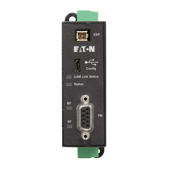
Profibus (DP) communication adapter module
Cam expansion port
USB conf. port
CAM link status LED
Power OK status LED
Profibus Bus Fault LED
Slave Fault LED
For use with PXR 20/25 electronic
trip units (ETUs). The PXR-PCAM
is designed to connect with a
circuit breaker's CAM-PXR link
and expand the communication
capabilities into a slave Profibus
DP interface.
The module also provides limited
discrete I/O, circuit breaker control
capability, and data storage rele-
vant to the breaker. The module
is mounted local to the breaker to
keep the CAM-PXR link limited to
3m maximum
WARNING
Be sure that all distribution
power is off when commission-
ing a PXR-PCAM with a circuit
breaker system. The module can
be powered temporarily via the
USB configuration port or
permanently with the 24 Vdc
power supply input.
IMPORTANT
Download the GSD file for the
PXR-PCAM on the Eaton website.
www.eaton.com/CAM
PIN
Signal
Shell
Ground
1
2
3
Profibus B/D+
4
RTS
5
ISO COM
6
ISO 5V
7
8
Profibus A/D-
9
18mm
Figure 1. Left = front view, right = side view
(0.71")
PXR –PCAM adapter
module specifications
Weight: 0.36 lb.
•
Housing width, height, length
•
(30 x 111 x 111mm)
Housing NEMA 1, IP20
•
Pollution degree 3, pcb is
•
conformally coated
Operational/storage
•
temperature: -20 to +70ºC / -45
to + 85ºC
Elevation: 0 - 2000m, humidity
•
5 - 95% noncondensing
CE mark, RoHS compliant
•
Safety: IEC/EN/UL61010-1, UL
•
file # E185559
CNL evaluation to CAN/
•
C22.2 No 1010.1.92
EMC EN61326 - IEC61000-4-X
•
level 3
Emmisions: conducted and
•
radiated
FCC part 15 & CISPR 11/22
•
class B
All terminal blocks are remov-
able, 5.08 mm (0.200") and
support wires of 0.2-2.03 mm
2
( 24-14 AWG). Ferrules recom-
mended for wire termination.
Power supply 24 Vdc +/- 20%,
6W maximum isolated CAM input
power with common/0V clamped
300V to GND. terminal identifica-
tion "TP .1-.3. " Connect TP1 near
CAM to assembly enclosure
ground as a functional ground.
Effective March 2017
NC
NC
NC
NC
DIN Three 24 Vdc +/-20% inputs
externally wetted, shared common
with ~5.0k ohm input impedance,
5mA draw. Terminal identification
TD.1-.4, shared with relay terminal.
DOUT − Two form A relays exter-
nally sourced, shared common hot
240 Vac/30 Vdc 2A CAT II max.
Terminal identification TD.5-.7 . In
breaker mode (command format
0), relay 1 (TD5) is used to close
the breaker when Profibus control
PXR-PCAM
DOUT
ISO
DIN
Figure 2. Discrete input and output connections
PXR-PCAM
Mounting foot
CAM/PXR link
24 Vdc
35mm
DIN rail
mount
Spring
clip
Mounting foot
DIN
Relay
is enabled, and relay 2 (TD6) is
used to open the breaker when
Profibus control is enabled. In
general mode (command format
1), relay 1 and relay 2 are used
for general purposes, and may be
independently opened and closed.
PB - DB9 Profibus DP interface,
shell grounded through TP1.
(see Figure 1)
Catalog
Ethernet
number
protocol Style #
PXR-PCAM Profibus
DP slave
Fuse
TD.7
COM
+
-
Source
RLY2
TD.6
Loads
RLY1
TD.5
Cassette
switches
IN1
TD.4
5mA each
input
IN2
TD.3
IN3
TD.2
COM
TD.1
+
-
24 Vdc
source
<30m
99mm
(3.9")
66D2355G01
Test
Rack out
Rack in
Advertisement
Table of Contents

Subscribe to Our Youtube Channel
Related Manuals for Eaton PXR-PCAM


Summary of Contents for Eaton PXR-PCAM
- Page 1 C22.2 No 1010.1.92 Source power is off when commission- EMC EN61326 - IEC61000-4-X • RLY2 TD.6 ing a PXR-PCAM with a circuit level 3 breaker system. The module can Loads Emmisions: conducted and • DOUT be powered temporarily via the RLY1 TD.5...
- Page 2 BETWEEN THE PARTIES. CAM Expansion port − future Figure 3. MCCB CAM-PXR link connections use only, do not connect. In no event will Eaton be responsible to the purchaser CAM-PXR Link − RS422 inter- or user in contract, in tort...
- Page 3 Not implemented 11 = w/ warning Not implemented 9..8 Uint16 (maximum value of I Amps Lmax Delete history Not implemented 1 = reset “Reset all min/max values” issued min/max to trip unit ProfibuS (DP) CommuniCation aDaPtEr moDulE IL120009EN March 2017 www.eaton.com...
- Page 4 (phase B current) Amps 7..6 Uint16 (phase C current) Amps 9..8 Uint16 (maximum value of I Amps Lmax 11..10 Uint16 (neutral current) Amps 13..12 Uint16 Volts L1-L2 15..14 Uint16 Volts L2-L3 ProfibuS (DP) CommuniCation aDaPtEr moDulE IL120009EN March 2017 www.eaton.com...
- Page 5 Frequency out of bounds alarm Historic trip occured Breaker in maintenance mode © 2017 Eaton Eaton All Rights Reserved 1000 Eaton Boulevard Eaton is a registered trademark. Printed in USA Cleveland, OH 44122 United States Publication No. IL120009EN / VCG All trademarks are property Eaton.com...
Need help?
Do you have a question about the PXR-PCAM and is the answer not in the manual?
Questions and answers