Advertisement
Instruction Leaflet IL012002EN
Instruction Leaflet for Modbus Power Monitoring/
Metering Module (PM3) for FD, JG, and KD/LG
Circuit Breakers and Motor Circuit Protectors
Contents
Description
1. Installation and Specifications ..............................................................................................................2
2. Indicators ..............................................................................................................................................9
3. Modbus RTU Communications ......................................................................................................... 10
4. Configuration and Input ...................................................................................................................... 11
5. Modbus Registers .............................................................................................................................. 12
Appendix A ......................................................................................................................................... 17
Effective March 2013
Page
Advertisement

Related Manuals for Eaton PM3


Summary of Contents for Eaton PM3
-
Page 1: Table Of Contents
Instruction Leaflet IL012002EN Effective March 2013 Instruction Leaflet for Modbus Power Monitoring/ Metering Module (PM3) for FD, JG, and KD/LG Circuit Breakers and Motor Circuit Protectors Contents Description Page 1. Installation and Specifications ......................2 2. Indicators ..............................9 3. Modbus RTU Communications ......................10 4. -
Page 2: Installation And Specifications
Instruction Leaflet for Modbus Power Monitoring/ Instruction Leaflet IL012002EN Metering Module (PM3) for FD, JG, and KD/LG Effective March 2013 Circuit Breakers and Motor Circuit Protectors 1. Installation and Specifications CAUTION 2. Insert unit into breaker. DO NOT ATTEMPT TO INSTALL OR PERFORM MAINTENANCE ON EQUIPMENT WHILE IT IS ENERGIZED. - Page 3 Instruction Leaflet for Modbus Power Monitoring/ Instruction Leaflet IL012002EN Metering Module (PM3) for FD, JG, and KD/LG Effective March 2013 Circuit Breakers and Motor Circuit Protectors 4. Insert screws in retainers. Figure 4. Inserting the Screws into the Retainers. 5. Tighten mounting screws to provided torque specifications.
- Page 4 13.5 Standard collars mounted on line and load end. Terminal Shield required. When using PM3 on KD breakers, LG terminals are required on load end of PM3. CAUTION TERMINAL SHIELDS MUST BE USED AS PER ORIGINAL CIRCUIT BREAKER INSTALLATION INSTRUCTIONS.
- Page 5 2.745 2.745 101.19 69.72 69.72 4.062 5.490 5.490 103.17 139.45 139.45 4.89 2X M5 x 0.8 124.21 Figure 7. Layout of KD 3 Pole with PM3. 3.568 90.63 1.375 3.438 1.375 34.93 87.33 34.93 3.342 .688 .688 87.17 17.48 17.48 .781...
- Page 6 Instruction Leaflet for Modbus Power Monitoring/ Instruction Leaflet IL012002EN Metering Module (PM3) for FD, JG, and KD/LG Effective March 2013 Circuit Breakers and Motor Circuit Protectors 3.501 88.93 1.375 1.375 3.385 34.93 34.93 85.98 .687 .687 3.188 17.45 17.45 80.98 .750...
- Page 7 Instruction Leaflet for Modbus Power Monitoring/ Instruction Leaflet IL012002EN Metering Module (PM3) for FD, JG, and KD/LG Effective March 2013 Circuit Breakers and Motor Circuit Protectors Table 3. PM3 Power Monitoring and Communications Module Specifications. Current Input Update Rate Pick up current 0.3A rms...
- Page 8 CAUTION FOR WYE SYSTEM, A NEUTRAL IS REQUIRED TO BE CONNECTED TO THE PM3 ON THE RIGHT PHOENIX CONNECTOR. IF NEUTRAL IS NOT AVAIL- ABLE, THE METER WILL CALCULATE A VIRTUAL NEUTRAL BASED ON THE PHASE-TO-PHASE RMS VOLTAGE. THE SYSTEM MUST BE BALANCED FOR THIS TO BE ACCURATE.
-
Page 9: Indicators
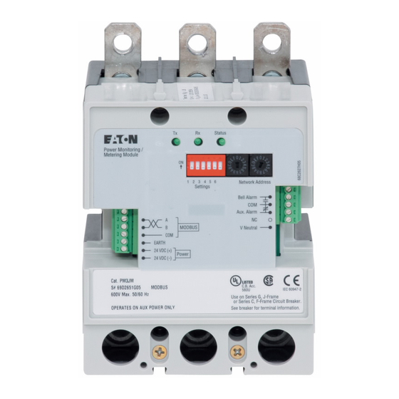
Instruction Leaflet for Modbus Power Monitoring/ Instruction Leaflet IL012002EN Metering Module (PM3) for FD, JG, and KD/LG Effective March 2013 Circuit Breakers and Motor Circuit Protectors 2. Indicators RX Led TX Led Status Red Bell Alarm Common Blue Aux Alarm... -
Page 10: Modbus Rtu Communications
Under certain circumstances, the PM3 will return an exception code. 04 – Read Input Registers; • If the function in the query is not supported by the PM3, exception 06 – Write Single Register; • code 01 is returned in the response. -
Page 11: Configuration And Input
Instruction Leaflet for Modbus Power Monitoring/ Instruction Leaflet IL012002EN Metering Module (PM3) for FD, JG, and KD/LG Effective March 2013 Circuit Breakers and Motor Circuit Protectors 4. Configuration and Input 4.1. User Options Dip Switch A six-position Dip Switch is used to set user options for the unit, as... -
Page 12: Modbus Registers
Instruction Leaflet for Modbus Power Monitoring/ Instruction Leaflet IL012002EN Metering Module (PM3) for FD, JG, and KD/LG Effective March 2013 Circuit Breakers and Motor Circuit Protectors 5.Modbus Registers 5.2. Breaker Status Breaker Status is transmitted in two discrete (bit) inputs, at address- Slave Actions, Supervisory, and Configuration Commands are es 100110 and 100210. - Page 13 Instruction Leaflet for Modbus Power Monitoring/ Instruction Leaflet IL012002EN Metering Module (PM3) for FD, JG, and KD/LG Effective March 2013 Circuit Breakers and Motor Circuit Protectors If the Breaker Status cannot be determined (for example, the con- 5.4. Standard Metered Values nector is not connected), an exception (0x82) code of 0x01 is Standard metered values are transmitted as 32-bit numbers.
- Page 14 Division Code = 32 – b5 b0 of Register Address 0x186E. • 5.6. Snapshot Energy The PM3 Modbus Module supports a control command to cap- ture energy. A write to Register Numbers 2911 (Address 0x0B5E) and 2912 (Address 0x0B5F) using Function Code 16 (0x10), Write Multiple Registers, is used for this purpose.
- Page 15 5.7. Snapshot Energy 5.8. Write Fixed-Point Data Multi-Register Configuration The PM3 Modbus Module supports a control command to capture Each Modbus register is defined in the Modbus protocol as a two- energy. A write to Register Numbers 2901 - 2903 (Address 0x0B54 byte entry.
- Page 16 Effective March 2013 Circuit Breakers and Motor Circuit Protectors 5.9. Modbus Diagnostics Registers The PM3 Modbus Add-on Module supports the sub-functions listed in Table 29. Modbus Function Code 08 provides a series of tests for checking the communications system or for checking various internal error condi- Table 29.
-
Page 17: Appendix A
Instruction Leaflet for Modbus Power Monitoring/ Instruction Leaflet IL012002EN Metering Module (PM3) for FD, JG, and KD/LG Effective March 2013 Circuit Breakers and Motor Circuit Protectors Appendix A Name Numeric Units Register Register Register Scale Format Function Number Address Address... - Page 18 Instruction Leaflet for Modbus Power Monitoring/ Instruction Leaflet IL012002EN Metering Module (PM3) for FD, JG, and KD/LG Effective March 2013 Circuit Breakers and Motor Circuit Protectors Notes: EATON CORPORATION www.eaton.com...
- Page 19 Instruction Leaflet for Modbus Power Monitoring/ Instruction Leaflet IL012002EN Metering Module (PM3) for FD, JG, and KD/LG Effective March 2013 Circuit Breakers and Motor Circuit Protectors Notes: EATON CORPORATION www.eaton.com...
- Page 20 The information, recommendations, descriptions, and safety nota- tions in this document are based on Eaton’s experience and judg- ment with respect to Retrofitting of Power Breakers. This instruction- al literature is published solely for information purposes and should not be considered all-inclusive.
Need help?
Do you have a question about the PM3 and is the answer not in the manual?
Questions and answers