Table of Contents
Advertisement
Quick Links
Instructions - Parts List
Leak Detection
System
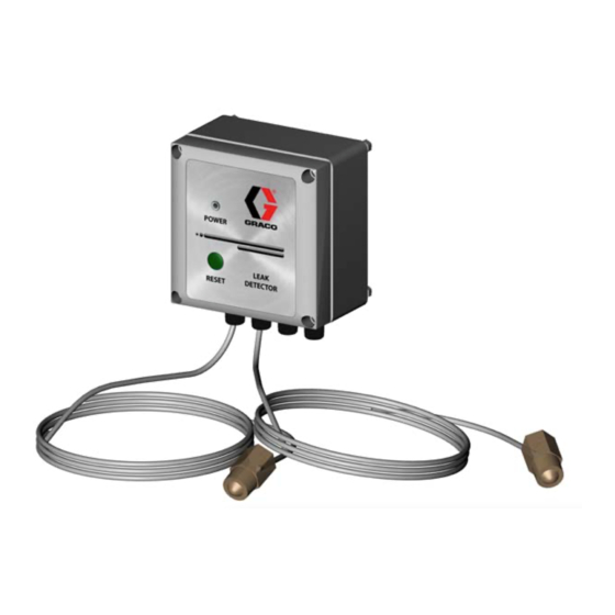
For detecting leaks in your diaphragm pump system.
Not for use in explosive atmospheres.
Part No. 234576 Leak Detection System
120 psi (0.8 MPa, 8 bar) Maximum Air Input Pressure
Part No. 24B290 Leak Detector Sensor Replacement Kit
Important Safety Instructions
Read all warnings and instructions in this manual.
Save these instructions.
See page 2 for Table of Contents.
311200D
TI6850A
Advertisement
Table of Contents

Subscribe to Our Youtube Channel
Related Manuals for Graco 234576


Summary of Contents for Graco 234576
- Page 1 311200D For detecting leaks in your diaphragm pump system. Not for use in explosive atmospheres. Part No. 234576 Leak Detection System 120 psi (0.8 MPa, 8 bar) Maximum Air Input Pressure Part No. 24B290 Leak Detector Sensor Replacement Kit Important Safety Instructions Read all warnings and instructions in this manual.
-
Page 2: Table Of Contents
Operation ....... . . 7 Graco Information ......10 Maintenance . -
Page 3: Overview
Overview Overview Usage Having both conductive and optical sensors allows the sensor to detect as many liquids as possible. When both sensors are in air, both lights (blue and yellow) flash The leak detector monitors air operated double dia- once per second. phragm pumps for diaphragm rupture or other leaks that may contaminate the fluid being pumped. -
Page 4: Installation
Installation Control Box Sensors TI6850A . 1. Leak Detection System Installation Install the Sensors To replace a sensor, order Part No. 24B290 Leak Detector Sensor Replacement Kit. The kit includes one sensor. To install the kit, first shut off power to the control box. - Page 5 Installation 5. Route the sensor wires into the control box through the fittings (F) at the bottom of the box. Tighten the fittings. If installing Part No. 24B290 Leak Detector Sensor 6. Attach the lead wires to the sensor terminals as Replacement Kit, shut off power to the control box shown in F .
- Page 6 To operate on 230 VAC, connect between pins marked N and 220. 1. Follow the instructions in your pump manual to ground the Graco diaphragm pump system and b. To operate from 110 VAC, connect between check its electrical grounding continuity.
-
Page 7: Operation
Operation Operation Leak Detector Operation If an error or a diaphragm rupture occurs, the LED and sensors will flash three times per second and the alarm will sound. The relay will trip and change state. To stop During normal operation, the LED on the leak detector the alarm, press the reset button or remove power for 30 control box and the sensors will flash once per second. -
Page 8: Troubleshooting
Troubleshooting Troubleshooting Problem Cause Solution Light flashes 3/sec and Sensor has detected liquid. Determine which sensor has detected the liquid. alarm sounds 1/sec. Inspect the diaphragm on the side which liquid has been detected. Replace diaphragm as necessary. To assure proper sensor operation, clean and dry the sensor head and the air side of the diaphragm pump. -
Page 9: Technical Data
Technical Data Technical Data Input voltage range ......12-28 VDC 100-130 VAC, 50/60 Hz 190-260 VAC, 50/60 Hz Maximum power consumption . -
Page 10: Graco Standard Warranty
With the exception of any special, extended, or limited warranty published by Graco, Graco will, for a period of twelve months from the date of sale, repair or replace any part of the equipment determined by Graco to be defective.
Need help?
Do you have a question about the 234576 and is the answer not in the manual?
Questions and answers