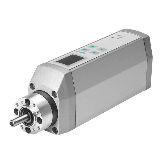
Festo MTR-DCI Series Brief Overview
Motor unit
Hide thumbs
Also See for MTR-DCI Series:
- Description (352 pages) ,
- User manual (203 pages) ,
- Brief overview (74 pages)

Subscribe to Our Youtube Channel
Related Manuals for Festo MTR-DCI Series


Summary of Contents for Festo MTR-DCI Series
- Page 1 Motoreinheit MTR−DCI Motor unit MTR−DCI Kurzübersicht Brief overview Typ MTR−DCI−... Deutsch English Español Français Italiano Svenska 713 995 0703b...
- Page 2 ......... . . Festo P.BE−K−MTR−DCI 0703b...
- Page 3 PDF−Datei auf der mitgelieferten CD−ROM enthalten ist. S Beachten Sie unbedingt die Informationen und Sicherheitshinweise in der vollständigen Beschreibung der Motoreinheit. S Bitte wenden Sie sich bei technischen Problemen an Ihren lokalen Festo−Service oder an folgende E−Mail− Adresse: service_international@festo.com Festo P.BE−K−MTR−DCI 0703b Deutsch...
- Page 4 Typ MTR−DCI−...−DN Englisch 553531 Installation und Inbetriebnahme Spanisch 553532 Steuerungsschnittstelle Französisch 553533 DeviceNet Italienisch 553534 usw. Schwedisch 553535 1) Je nach Versionsstand. 2) Dateiname = <Teilenummer> + <Sprachkennung>. Unter dieser Teile nummer auch als Papierversion erhältlich. Festo P.BE−K−MTR−DCI 0703b Deutsch...
- Page 5 Weitere Informationen finden Sie im Hilfesystem der Konfi gurationssoftware FCT und in den Bedienungsanleitungen des Zubehörs (z. B. Referenzschalter, Achse). Übergeordnete Steuerung Software−Ebene: Festo Configuration Tool (FCT) Antriebsebene: Motoreinheit Kupplung + Gehäuse Achse Festo P.BE−K−MTR−DCI 0703b Deutsch...
- Page 6 Funktion Statusanzeige > Hauptmenü MENU Menu Eingabe verwerfen oder Menüebene zurück EMERG.STOP Aktuellen Positioniervorgang abbrechen Bestätigt Auswahl bzw. Eingabe Enter SAVE Speichert Parametereinstellungen dauerhaft START/STOP Startet/stoppt Demo−Modus Vorheriger/nächster Menübefehl oder manuell verfahren (Teachen) EDIT Vergrößert/verkleinert Parameterwert Festo P.BE−K−MTR−DCI 0703b Deutsch...
- Page 7 Stecker MTR−DCI−...−PB: PROFIBUS−DP−Schnittstelle Sub−D 9−polig Buchse MTR−DCI−...−CO: CANopen−Schnittstelle Sub−D 9−polig Stecker MTR−DCI−...−DN: DeviceNet−Schnittstelle Sub−D 9−polig Stecker Spannungs Sub−D, 2−polig Spannungsanschluss mit versorgung Stecker Hochstrom−Kontakten 1) mit Schraubverriegelung (Außengewinde), z. B. Referenzschalter SMT−8F/8M−...−M8D. Verlängerungskabel für Referenzschalter: KM8−M8−GSGD−... Festo P.BE−K−MTR−DCI 0703b Deutsch...
- Page 8 Die LED I/F ist abhängig vom Typ des MTR−DCI: LED I/F MTR−DCI−...−IO Positionier leuchtet grün Betriebsbereit, Freigabe liegt vor status status leuchtet rot Nicht betriebsbereit, Freigabe fehlt (Zweifarb− LED) grün/rot Betriebsbereit, Freigabe fehlt Positionierbetrieb oder Störung Festo P.BE−K−MTR−DCI 0703b Deutsch...
- Page 9 CAN Zustand stopped" (single flash) CAN Zustand pre−operational" (blinking) Rot: Verbindung fehlerfrei (off ) Verbindung Verbindung CAN Warning Limit reached (single flash) CAN Node Guarding error (double flash) Busparameter nicht parametriert oder externe CAN−Versorgung fehlt (on) Festo P.BE−K−MTR−DCI 0703b Deutsch...
- Page 10 LED I/F MTR−DCI−...−DN Grün: Zustand Operational" Busstatus (on) "Network" "Network" Zustand Device Standby" (blinking) Rot: Keine Bus−Verbindung No Power/Bus− Busstatus Off (off ) "Module "Module " " Warnung Minor fault" (blinking) Fehler Unrecoverable fault" (on) Festo P.BE−K−MTR−DCI 0703b Deutsch...
- Page 11 5 A träge 7 A träge 10 A träge 25 A träge 1) Die Toleranz muss direkt am Spannungsanschluss eingehalten werden. 2) Angaben für die Lastspannungsversorgung. 3) Empfohlen. 4) Bei getrennter Logikspannungsversorgung: Logik 24 VDC ±10 %. Festo P.BE−K−MTR−DCI 0703b Deutsch...
- Page 12 MTR−DCI mit folgenden Kabeln anschließen (max. Länge beachten). Kabel max. Zubehör−Typ Versorgungskabel KPWR−MC−1−SUB−9HC−... 10 m Programmierkabel KDI−MC−M8−SUB−9−... 2,5 m Steuerkabel (nur MTR−DCI−...−IO) KES−MC−1−SUB−9HC−... 30 m Feldbusadapter Zubehör−Typ FBA−CO−SUB−9−M12 MTR−DCI−...−CO MTR−DCI−...−PB FBA−PB−SUB−9−3XM12 MTR−DCI−...−DN FBA−CO−SUB−9−M12 zur getrennten Versorgung von Last− und Logikspannung Festo P.BE−K−MTR−DCI 0703b Deutsch...
- Page 13 Erstinbetriebnahme, nach Änderung des Maßbezugssystems (Referenzfahrtmethode, Achsennullpunkt, Drehrichtung (vgl. Objekt 607E bei MTR−DCI−... −IO: bei Warnung LAST ACTUAL POSITION NOT SAVED; mit nicht selbsthemmendem Antrieb nach jedem Einschalten, bei MTR−DCI−... −PB/CO/DN nach jedem Einschalten der Logikspannung. Festo P.BE−K−MTR−DCI 0703b Deutsch...
- Page 14 Führen Sie die Inbetriebnahme mit der Konfigurationssoft ware Festo Configuration Tool durch (siehe FCT−Hilfesystem) oder optional mit dem Bedienfeld (nur Typ MTR−DCI−...H2). Überblick zur Inbetriebnahme: 1. Achse auswählen und Parametrierung anpassen. Ggf. Feldbusadresse einstellen. 2. Parameter für die Referenzfahrt einstellen:...
- Page 15 S It is essential that you observe the information and the safety instructions in the complete manual for the motor unit. S Please consult your local Festo Service or write to the following e−mail address if you have any technical problems: service_international@festo.com...
- Page 16 Installation and commissioning Spanish 553532 DeviceNet control interface French 553533 etc. Italian 553534 Swedish 553535 1) Depending on version status. 2) File name = <part number> + <language code>. Also available in paper version under this part number. Festo P.BE−K−MTR−DCI 0703b English...
- Page 17 Further information can be found in the help system of the FCT configuration software and in the operating in structions for the accessories (e. g. reference switch, axis). Higher−order controller Software level: Festo Configuration Tool (FCT) Drive level: Motor unit Coupling + housing Axis Festo P.BE−K−MTR−DCI 0703b English...
-
Page 18: Displays And Connections
Reject entry or return to menu level EMERG.STOP Abort current positioning procedure Confirms the selection or entry Enter SAVE Saves parameter settings permanently START/STOP Starts/stops the Demo Mode Previous/next menu command or position manually (Teach) EDIT Increases/reduces parameter value Festo P.BE−K−MTR−DCI 0703b English... - Page 19 Sub−D 9−pin Plug MTR−DCI−...−DN: DeviceNet interface Sub−D 9−pin Plug Power Sub−D, 2−pin Voltage connection with high− supply Plug current contacts 1) with screw locking (external thread), e. g. reference switch SMT−8F/8M−...−M8D. Extension cable for reference switch: KM8−M8−GSGD−... Festo P.BE−K−MTR−DCI 0703b English...
- Page 20 The I/F LED depends on the type of the MTR−DCI: I/F LED MTR−DCI−...−IO Positioning lights up green Ready to operate; is enabled status status lights up red Not ready to operate, not enabled (two−colour LED) green/red Ready to operate; not enabled Positioning operation or fault Festo P.BE−K−MTR−DCI 0703b English...
- Page 21 CAN status stopped"(single flash) CAN status pre−operational" (blinking) red: Fault−free connection (off ) connection CAN warning limit reached (single flash) CAN Node guarding error (double flash) Bus parameter not parametrized or no external CAN supply (on) Festo P.BE−K−MTR−DCI 0703b English...
- Page 22 LED I/F MTR−DCI−...−DN Green: Status Operational" Bus status (on) "Network" "Network" Status Device standby" (blinking) Red: No bus connection No Power/Bus−Off Bus status (off ) "Module "Module " " Warning Minor fault" (blinking) Fault Unrecoverable fault" (on) Festo P.BE−K−MTR−DCI 0703b English...
- Page 23 25 A slow− blowing blowing blowing blowing 1) The tolerance must be observed directly at the voltage connection. 2) Specifications for the load voltage supply 3) Recommended 4) with separate logic voltage supply: logic 24 V DC ±10%. Festo P.BE−K−MTR−DCI 0703b English...
- Page 24 Supply cable KPWR−MC−1−SUB−9HC−... 10 m Programming cable KDI−MC−M8−SUB−9−... 2.5 m Control cable (only MTR−DCI−...−IO) KES−MC−1−SUB−9HC−... 30 m Field bus adapter Accessories type FBA−CO−SUB−9−M12 MTR−DCI−...−CO MTR−DCI−...−PB FBA−PB−SUB−9−3XM12 MTR−DCI−...−DN FBA−CO−SUB−9−M12 for separate supply of load voltage and logic voltage Festo P.BE−K−MTR−DCI 0703b English...
- Page 25 (compare object 607E with MTR−DCI−... −IO: with the warning LAST ACTUAL POSITION NOT SAVED; with non−self locking drive each time the device is switched on, with MTR−DCI−... −PB/CO/DN each time the logic voltage is switched on. Festo P.BE−K−MTR−DCI 0703b English...
- Page 26 Carry out commissioning with the Festo Configuration Tool configuration software (see FCT help system), or optionally with the control panel (only type MTR−DCI−...H2). Overview of commissioning 1. Select the axis and adapt the parametrization. If necessary, set the field bus address.
-
Page 27: Instrucciones Para El
S Es esencial que observe la información y las instrucciones de seguridad en el manual completo del motor. S Consulte con el servicio local de Festo o escriba a la siguiente dirección de correo electrónico si tiene difi cultades técnicas: service_international@festo.com... - Page 28 Francés 553533 Italiano 553534 Sueco 553535 1) Según el estado de la versión. 2) Nombre de archivo = <nº de artículo> + <identificador de idioma>. También disponible en versión impresa con este número de artículo. Festo P.BE−K−MTR−DCI 0703b Español...
- Page 29 FCT y en las instrucciones de funcionamiento de los accesorios (p. ej., interruptor de referencia, eje, etc.). Unidad de control de nivel superior Nivel de software: Festo Configuration Tool (FCT) Nivel de acciona miento: Motor Cuerpo + acopla miento Festo P.BE−K−MTR−DCI 0703b Español...
- Page 30 Confirma la selección o la entrada actual Enter SAVE Guarda permanentemente los ajustes de parámetros START/STOP Inicia/detiene el modo Demo Anterior/siguiente orden de menú o desplazar manualmente (teach) EDIT Aumenta/reduce el valor del parámetro Festo P.BE−K−MTR−DCI 0703b Español...
- Page 31 Alimenta Sub−D, 2 pines Conexión de la tensión ción Conector con contactos de elevada corriente 1) Con tuerca de bloqueo (rosca exterior), p. ej., interruptor de referencia SMT−8F/8M−...−M8D. Cable de extensión para interruptor de referencia: KM8−M8−GSGD−... Festo P.BE−K−MTR−DCI 0703b Español...
- Page 32 LED I/F MTR−DCI−...−IO Estado del Encendido en Operacional, está habilitado posiciona verde miento miento (LED Encendido en rojo No dispuesto para funcionar y habilitación ausente bicolor) Verde/rojo Operacional, no está habilitado Modo de posicionamiento o fallo Festo P.BE−K−MTR−DCI 0703b Español...
- Page 33 Estado del CAN stopped" (single flash) estado Estado del CAN pre−operational" (blinking) Rojo: Conexión perfecta (off) conexión conexión de bus CAN Warning Limit reached (single flash) CAN Node guarding error (double flash) Bus sin parametrizar o falta alimentación CAN externa (on) Festo P.BE−K−MTR−DCI 0703b Español...
- Page 34 LED I/F MTR−DCI−...−DN Verde: Estado Operational" Estado del (on) Estado Device standby" "Network" (blinking) Rojo: Sin conexión bus No Power/Bus−Off Estado del (off ) "Module " Advertencia Minor fault" (blinking) Error Unrecoverable fault" (on) Festo P.BE−K−MTR−DCI 0703b Español...
- Page 35 1) La tolerancia se debe respetar en la misma conexión de tensión. 2) Especificaciones para la alimentación de tensión de la carga. 3) Recomendado. 4) Si la alimentación de la tensión de la lógica está separada: lógica 24 V DC ±10 %. Festo P.BE−K−MTR−DCI 0703b Español...
- Page 36 2,5 m Cable de control (sólo para MTR− KES−MC−1−SUB−9HC−... 30 m DCI−...−IO) Adaptador de bus de campo Tipo de accesorios FBA−CO−SUB−9−M12 MTR−DCI−...−CO MTR−DCI−...−PB FBA−PB−SUB−9−3XM12 MTR−DCI−...−DN FBA−CO−SUB−9−M12 para alimentación separada de las tensiones de carga y de lógica Festo P.BE−K−MTR−DCI 0703b Español...
- Page 37 MTR−DCI−... −IO: si aparece la advertencia LAST ACTUAL POSITION NOT SAVED; con un actuador que no sea autoblocante, después de cada conexión con el MTR−DCI−... −PB/CO/DN cada vez que se conecte la tensión de la lógica Festo P.BE−K−MTR−DCI 0703b Español...
- Page 38 Efectúe la puesta a punto con el software de configuración Festo Configuration Tool (véase la ayuda del sistema FCT) u, opcionalmente, con el panel de control (sólo con el tipo MTR−DCI−...H2). Resumen de la puesta a punto: 1. Seleccione el eje y adapte la parametrización.
- Page 39 S En cas de problème technique, merci de vous adres ser au service après−vente Festo le plus proche ou d’envoyer un courrier électronique à l’adresse sui vante : service_international@festo.com...
- Page 40 Installation et mise en service Espagnol 553532 Interface de commande Français 553533 DeviceNet Italien 553534 etc. Suédois 553535 1) Selon la configuration. 2) Nom de fichier = <référence> + <code de langue>. Egalement disponible en version papier sous cette référence. Festo P.BE−K−MTR−DCI 0703b Français...
- Page 41 FCT et aux notices d’utilisation des accessoires (p. ex. capteur de référence, axe). Commande de niveau supérieur Niveau logiciel : Festo Configuration Tool (FCT) Niveau entraîne ment : Unité motrice Accouplement + carter Festo P.BE−K−MTR−DCI 0703b Français...
- Page 42 Confirmation de la sélection ou de la saisie Enter SAVE Enregistrement permanent des réglages de START/STOP paramètres Lancement/arrêt du mode Démo Passage à la commande de menu précédente/ suivante ou procédure manuelle (Teach EDIT Apprentissage) Augmentation/réduction de la valeur du paramètre Festo P.BE−K−MTR−DCI 0703b Français...
- Page 43 Sub−D à 9 pôles Connecteur(s) mâle(s) Alimentation Sub−D, à 2 pôles Connecteur d’alimentation électrique Connecteur(s) avec contacts de puissance mâle(s) 1) avec verrouillage par vis (filetage), p. ex. capteur de référence SMT−8F/8M−...−M8D. Prolongateur pour capteur de référence : KM8−M8−GSGD−... Festo P.BE−K−MTR−DCI 0703b Français...
- Page 44 LED I/F MTR−DCI−...−IO Etat de est allumée Opérationnel, validation disponible positionne en vert ment (DEL ment (DEL bicolore) est allumée Non opérationnel, validation en rouge manquante vert/rouge Opérationnel, validation manquante éteinte Mode de positionnement ou panne Festo P.BE−K−MTR−DCI 0703b Français...
- Page 45 Etat CAN « pre−operational » (blinking) Rouge : Connexion sans erreur (off) Connexion Connexion CAN warn limit reached (single flash) CAN Node guarding error (double flash) Paramètre de bus non paramétré ou ali mentation CAN externe absente (on) Festo P.BE−K−MTR−DCI 0703b Français...
- Page 46 Etat Operational" Etat du bus (on) "Network" "Network" Etat Device standby" (blinking) Rouge: Pas de connexion bus Etat du bus No Power/Bus−Off (off ) "Module "Module " " Avertissement Minor fault" (blinking) Erreur Unrecoverable fault" (on) Festo P.BE−K−MTR−DCI 0703b Français...
- Page 47 1) La tolérance doit être respectée directement sur le raccord d’alimentation. 2) Indications pour l’alimentation en tension sous charge. 3) Recommandé. 4) En cas d’alimentation en tension logique séparée: logique 24 VCC ±10 %. Festo P.BE−K−MTR−DCI 0703b Français...
- Page 48 Câble de programmation MC−1−SUB−9HC−... 2,5 m Câble de commande (uniquement KDI−MC−M8−SUB−9−... 30 m MTR−DCI−...−IO) KES−MC−1−SUB−9HC−... Adaptateur de bus de terrain Type d’accessoire MTR−DCI−...−CO FBA−CO−SUB−9−M12 MTR−DCI−...−PB FBA−PB−SUB−9−3XM12 MTR−DCI−...−DN FBA−CO−SUB−9−M12 pour alimentation séparée des tensions de charge et de logique Festo P.BE−K−MTR−DCI 0703b Français...
- Page 49 (voir objet 607E pour MTR−DCI−... −IO : en cas d’avertissement LAST ACTUAL POSITION NOT SAVED; avec des entraînements non−autoblocants après chaque mise en marche, pour MTR−DCI−... −PB/CO/DN après chaque mise en marche de la tension logique. Festo P.BE−K−MTR−DCI 0703b Français...
- Page 50 Effectuez la mise en service à l’aide du logiciel de configu ration Festo Configuration Tool (voir le système d’aide FCT) ou, en option, avec le pupitre de commande (uniquement type MTR−DCI−...H2). Aperçu de la mise en service : 1. Sélectionner l’axe et ajuster le paramétrage.
- Page 51 S Osservare assolutamente le informazioni e le norme di sicurezza riportate nella descrizione completa dell’unità motore. S Se dovessero sorgere problemi tecnici, rivolgersi al servizio assistenza locale Festo o al seguente indi rizzo e−mail: service_international@festo.com Festo P.BE−K−MTR−DCI 0703b Italiano...
- Page 52 DeviceNet Francese 553533 ecc. Italiano 553534 Svedese 553535 1) A seconda della data. 2) Nome file = <codice prodotto> + <identificazione della lingua>. Dispo nibile anche in versione cartacea con questo codice prodotto. Festo P.BE−K−MTR−DCI 0703b Italiano...
- Page 53 FCT e nelle istruzioni d’uso degli accessori (ad es. interruttore di riferimento, asse). Comando principale Livello software: Festo Configuration Tool (FCT) Livello di aziona mento: unità motore giunto + copri giunto asse Festo P.BE−K−MTR−DCI 0703b Italiano...
- Page 54 EMERG.STOP Interrompere processo di posizionamento attuale Conferma selezione o impostazione Enter SAVE Memorizza permanentemente le impostazioni dei parametri START/STOP Avvia/arresta modalità Demo Comando di menu precedente/successivo o traslazione manuale (teach) EDIT Aumenta/riduce valore di parametro Festo P.BE−K−MTR−DCI 0703b Italiano...
- Page 55 SUB−D a 2 poli Collegamento della tensione zione di ten connettore con contatti per correnti forti sione maschio 1) con bloccaggio a vite (filettatura esterna), ad es. interruttore di riferimento SMT−8F/8M−...−M8D. Cavo di prolunga per interruttore di riferimento: KM8−M8−GSGD−... Festo P.BE−K−MTR−DCI 0703b Italiano...
- Page 56 Il LED I/F dipende dal tipo di unità MTR−DCI: LED I/F MTR−DCI−...−IO Stato di verde Pronto, abilitazione presente posiziona posiziona rosso Non pronto, abilitazione mancante mento (LED a due verde/rosso Pronto, abilitazione mancante colori) colori) spento Esercizio di posizionamento o guasto Festo P.BE−K−MTR−DCI 0703b Italiano...
- Page 57 Stato CAN stopped" (single flash) Stato CAN pre−operational" (blinking) Rosso: Collegamento corretto (off) collega collega mento bus CAN Warning Limit reached (single flash) CAN Node guarding error (double flash) Parametro bus non parametrizzato oppure manca alimentazione CAN esterna (on) Festo P.BE−K−MTR−DCI 0703b Italiano...
- Page 58 MTR−DCI−...−DN Verde Stato Operational" Stato bus (on) "Network" "Network" Stato Device standby" (blinking) Rosso: Nessun collegamento bus Stato bus No Power/Bus−Off (off ) "Module "Module " " Avvertenza Minor fault" (blinking) Errore Unrecoverable fault" (on) Festo P.BE−K−MTR−DCI 0703b Italiano...
-
Page 59: Istruzioni Di Montaggio E Installazione
5 A ritardato 7 A ritardato 10 A ritardato 25 A ritardato esterno 1) Osservare la tolleranza direttamente sulla connessione della tensione. 2) Indicazioni per l’alimentazione della tensione di carico. 3) Raccomandato. 4) In caso di alimentazione separata della tensione di carico: logica 24 VCC ±10 %. Festo P.BE−K−MTR−DCI 0703b Italiano... - Page 60 10 m Cavo di programmazione KDI−MC−M8−SUB−9−... 2,5 m Cavo di comando KES−MC−1−SUB−9HC−... 30 m (solo MTR−DCI−...−IO) Adattatore fieldbus Tipo di accessori FBA−CO−SUB−9−M12 MTR−DCI−...−CO MTR−DCI−...−PB FBA−PB−SUB−9−3XM12 MTR−DCI−...−DN FBA−CO−SUB−9−M12 per alimentazione separata di tensione di carico e tensione logica Festo P.BE−K−MTR−DCI 0703b Italiano...
- Page 61 (cfr. oggetto 607E con MTR−DCI−... −IO: quando appare l’avvertenza LAST ACTUAL POSITION NOT SAVED; dopo ogni avvio in caso di attuatore a bloccaggio non automatico, con MTR−DCI−... −PB/CO/DN dopo ogni inserzione della tensione logica. Festo P.BE−K−MTR−DCI 0703b Italiano...
- Page 62 Eseguire la messa in servizio con il software Festo Configuration Tool (vedi aiuto dell’FCT) oppure, opzionalmente, con il pannello di comando (solo tipo MTR−DCI−...H2). Panoramica della messa in servizio: 1. Selezionare l’asse e adattare la parametrizzazione. Impostare l’indirizzo Fieldbus se necessario.
- Page 63 S Läs och följ all information och alla säkerhets anvisningar i den fullständiga beskrivningen till motorenheten. S Kontakta närmaste Festo−serviceavdelning eller skriv till följande e−postadress vid eventuella tekniska pro blem: service_international@festo.com Festo P.BE−K−MTR−DCI 0703b Svenska...
- Page 64 MTR−DCI−...−DN Engelska 553531 Installation och idrifttagning Spanska 553532 Kontrollgränssnitt DeviceNet Franska 553533 osv. Italienska 553534 Svenska 553535 1) Beroende på version. 2) Filnamn = <Artikelnummer> + <Språkkod>. Finns även i pappersver sion med samma artikelnummer. Festo P.BE−K−MTR−DCI 0703b Svenska...
- Page 65 Ytterligare information finns i hjälpsystemet för konfigura tionsprogrammet FCT och i bruksanvisningarna till tillbe hören (t.ex. referensgivare, axel). Överordnat styrsystem Programnivå: Festo Configuration Tool (FCT) Drivenhetsnivå: Motorenhet Koppling + hus Axel Festo P.BE−K−MTR−DCI 0703b Svenska...
- Page 66 Statusindikering > Huvudmeny MENU Menu Ångra inmatning eller gå tillbaka en menynivå EMERG.STOP Avbryt aktuellt positioneringsförlopp Bekräfta val resp. inmatning Enter SAVE Spara parameterinställningar permanent START/STOP Startar/stoppar demo−läge Föregående/nästa menykommando eller manuell körning (inlärning) EDIT Minskar/ökar parametervärdet Festo P.BE−K−MTR−DCI 0703b Svenska...
- Page 67 (PLC/IPC) (PLC/IPC) MTR−DCI−...−PB: PROFIBUS−DP−gränssnitt D−sub 9−polig Uttag MTR−DCI−...−CO: CANopen−gränssnitt D−sub 9−polig Kontakt MTR−DCI−...−DN: DeviceNet−gränssnitt D−sub 9−polig Kontakt Spännings D−sub, 2−polig Spänningsanslutning med försörjning Kontakt högspänningskontakter 1) med skruvlåsning (yttergänga), t.ex. referensgivare SMT−8F/8M−...−M8D. Förlängningskabel för referensgivare: KM8−M8−GSGD−... Festo P.BE−K−MTR−DCI 0703b Svenska...
- Page 68 Inget internt fel har rapporterats. LED I/F är beroende av typ av MTR−DCI: LED I/F MTR−DCI−...−IO Positioner Lyser grönt Driftklar, aktivering finns ingsstatus ingsstatus Lyser rött Inte driftklar, aktivering saknas (tvåfärgs− LED) Grön/röd Driftklar, aktivering saknas Positioneringsläge eller störning Festo P.BE−K−MTR−DCI 0703b Svenska...
- Page 69 Tillstånds maskin CAN−tillstånd "stopped" (single flash) CAN−tillstånd "pre−operational" (blinking) Röd: Anslutning felfri (off) Anslutning Anslutning buss CAN Warning Limit reached (single flash) CAN Node guarding error (double flash) Bussparameter inte parametrerad eller extern CAN−försörjning saknas (on) Festo P.BE−K−MTR−DCI 0703b Svenska...
- Page 70 LED I/F MTR−DCI−...−DN Grön: Tillstånd Operational" Busstatus (on) "Network" "Network" Tillstånd Device standby" (blinking) Röd: Ingen anslutning buss Busstatus No Power/Bus−Off (off ) "Module "Module " " Varning Minor fault" (blinking) Fel Unrecoverable fault" (on) Festo P.BE−K−MTR−DCI 0703b Svenska...
- Page 71 Ext. säkring 5 A, trög 7 A, trög 10 A, trög 25 A, trög 1) Toleransen måste gälla direkt vid spänningsanslutningen. 2) Uppgifter för matningsspänningsförsörjningen. 3) Rekommenderat. 4) Vid isolerad logikspänningsförsörjning: Logik 24 VDC ±10 %. Festo P.BE−K−MTR−DCI 0703b Svenska...
- Page 72 (beakta max.längd). Kabel max. Tillbehörstyp Försörjningskabel KPWR−MC−1−SUB−9HC−... 10 m Programmeringskabel KDI−MC−M8−SUB−9−... 2,5 m Styrkabel (endast MTR−DCI−...−IO) KES−MC−1−SUB−9HC−... 30 m Adapter för fältbuss Tillbehörstyp FBA−CO−SUB−9−M12 MTR−DCI−...−CO MTR−DCI−...−PB FBA−PB−SUB−9−3XM12 MTR−DCI−...−DN FBA−CO−SUB−9−M12 för isolerad försörjning av matnings− och lastspänning Festo P.BE−K−MTR−DCI 0703b Svenska...
- Page 73 ändrats (referenskörningsmetod, axelnollpunkt, rotationsriktning (jfr. objekt 607E på MTR−DCI−... −IO: vid varningen LAST ACTUAL POSITION NOT SAVED; med icke−självhämmande drivenhet efter varje tillkoppling, på MTR−DCI−... −PB/CO/DN efter varje tillkoppling av logikspänningen. Festo P.BE−K−MTR−DCI 0703b Svenska...
- Page 74 Genomför idrifttagningen med konfigurationsprogrammet Festo Configuration Tool (se FCT−hjälpsystem) eller med manöverpanelen (endast typ MTR−DCI−...H2). Översikt över idrifttagningen: 1. Välj axel och anpassa parametreringen. Ställ ev. in fältbussadressen. 2. Ställ in parametrar för referenskörning: Referenskörningsmetod Sökhastighet till referenspunkten Rörelsehastighet till axelnollpunkten.
Need help?
Do you have a question about the MTR-DCI Series and is the answer not in the manual?
Questions and answers