Festo MTR-DCI Series Brief Overview
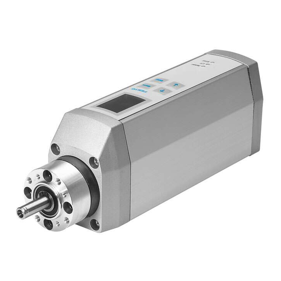
Motor unit
Hide thumbs
Also See for MTR-DCI Series:
- Description (352 pages) ,
- User manual (203 pages) ,
- Brief overview (74 pages)
Advertisement
Available languages
Available languages
Quick Links
Download this manual
See also:
User Manual
Motoreinheit MTR−DCI
Motor unit MTR−DCI
Kurzübersicht
Brief overview
Typ MTR−DCI−...
Typ MTR−DCI−...IO
Deutsch
English
Español
Français
Italiano
Svenska
693 431
a
0606
Advertisement

Subscribe to Our Youtube Channel
Related Manuals for Festo MTR-DCI Series


Summary of Contents for Festo MTR-DCI Series
- Page 1 Motoreinheit MTR−DCI Motor unit MTR−DCI Kurzübersicht Brief overview Typ MTR−DCI−... Typ MTR−DCI−...IO Deutsch English Español Français Italiano Svenska 693 431 0606...
-
Page 2: Table Of Contents
......... . . Festo P.BE−K−MTR−DCI 0606a... -
Page 3: Deutsch
Hinweis S Beachten Sie unbedingt die Informationen und sicherheitstechnischen Hinweise in der vollständigen Beschreibung der Motoreinheit. S Bitte wenden Sie sich bei technischen Problemen an Ihren lokalen Festo−Service oder an folgende E−Mail Adresse: service_international@festo.com Inhalt der CD−ROM Sprache Dateiname Beschreibung der Motoreinheit... - Page 4 Funktion und Anwendung Die Motoreinheit Typ MTR−DCI−... ist ein intelligenter Stell motor, mit Gleichstrommotor, Planetengetriebe, Encoder und integrierter Steuerungselektronik (Positioniersteue rung und Lageregler). Übergeordnete Steuerung Software−Ebene: Festo Configuration Tool Antriebsebene: Motoreinheit Kupplung + Ge häuse Achse Festo P.BE−K−MTR−DCI 0606a Deutsch...
- Page 5 Mechanische Auslegung und Anbauschnittstelle des MTR− DCI sind für den Einsatz mit elektrischen Stellachsen (z.B. Typ DMES−..., DGE−...) von Festo optimiert. Die Motorein heit ist jedoch auch für kundenspezifische Stellfunktionen mit langsamen Spindelantrieben einsetzbar. Die Achse kann direkt über stirnseitige Gewinde am Getriebe des MTR−DCI montiert werden, oder über axiale Verbindungse...
- Page 6 Betriebsspannung liegt an Keine Betriebsspannung LED I/F Positionierstatus (I/F: Interface/Fieldbus) grün Positioniervorgang abgeschlossen (MC) Positioniervorgang gestoppt und Freigabe fehlt grün/rot Positioniervorgang gestoppt oder Freigabe fehlt Positionierbetrieb LED ERROR Fehleranzeige Interner Fehler Kein interner Fehler festgestellt Festo P.BE−K−MTR−DCI 0606a Deutsch...
- Page 7 Stecker mit Hoch−Stromkontakten Steuerung D−Sub, 9−polig Schnittstelle zum Anschluss an Typ −IO: beliebige SPS−Steuerung Stecker Referenz M8x1, 3−polig Sensoreingang für Referenz schalter Buchse schalter: Schließer (N.O. nor mally open); PNP. Anschlusskabel mit Schraubverriegelung M8x1 (Außengewinde). Festo P.BE−K−MTR−DCI 0606 Deutsch...
- Page 8 Bestätigt die aktuelle Auswahl bzw. Eingabe. Enter Enter SAVE Speichert Parametereinstellungen dauerhaft START/ Startet oder stoppt einen Positioniervorgang (nur im STOP Demo−Mode). <− −> Scrollt innerhalb einer Menüebene zur Auswahl eines Menübefehles. EDIT Stellt Parameter ein. Festo P.BE−K−MTR−DCI 0606a Deutsch...
- Page 9 Start der Positionierfahrt Verfahrsatztabelle" Homing Start der Referenzfahrt 1) 2) Settings Auswahl des Antriebs, Parametrierung, Programmierung der Verfahrsätze Axis type Type DMES−... Festo Linearachse Typ DMES−... Rotation drive Rotationsachse mit Anschlag User config Beliebiger Linearantrieb Axis param Zero point Offset des Achsennullpunkts Abs.min.pos Hubbegrenzung: Software−End...
- Page 10 Password Einrichten eines lokalen (Bedienfeld−) Kennworts mit 3 Ziffern HMI control Voreinstellung der Gerätesteuerung über Bedien feld LCD adjustment Drehen der Anzeige im Display in 90° Schritten Passwort−Schutz Steuerungsschnittstelle muss deaktiviert werden, siehe [HMI con trol]:HMI=on Festo P.BE−K−MTR−DCI 0606a Deutsch...
- Page 11 Damit vermeiden Sie bei Stromunterbrechungen ein plötzliches Abwärtsgleiten der Arbeitsmasse. Warnung Verwenden Sie ausschließlich Stromquellen, die eine sichere elektrische Trennung der Betriebsspannung nach IEC/DIN EN 60204−1 gewährleisten. Berücksichti gen Sie zusätzlich die allgemeinen Anforderungen an PELV−Stromkreise gemäß IEC/DIN EN 60204−1. Festo P.BE−K−MTR−DCI 0606 Deutsch...
- Page 12 7,7 A ±20% 20 A ±20% Netzgerät 24VDC/3A 24VDC/6A 24VDC/10A 48VDC/10A ext. Siche 5 A träge 7 A träge 10 A träge 25 A träge rung, sekun därseitig Die Toleranz muss auch noch direkt am Spannungsanschluss eingehalten werden. Festo P.BE−K−MTR−DCI 0606a Deutsch...
- Page 13 Warnung LAST ACTUAL POSITION NOT SAVED! bei nicht selbsthemmendem Antrieb nach jedem Einschalten Führen Sie die Inbetriebnahme mit der Konfigurationssoft ware Festo Configuration Tool durch (siehe FCT−Hilfesystem) oder optional mit dem Bedienfeld (nur Typ MTR−DCI−...H2) wie folgt: Festo P.BE−K−MTR−DCI 0606...
- Page 14 Zum Abschluss der Inbetriebnahme: Fahrverhalten der Achse, Bezugskoordinaten und Ar beitsbereich prüfen (Probefahrt). Einstellungen der Verfahrsätze, Bezugskoordinaten und Arbeitsbereich ggf. optimieren. Steuerungsschnittstelle testen (Gerätesteuerung mit Bedienfeld HMI = off ). Einstellungen vor Fremdzugriff über Kennwort schüt zen. Festo P.BE−K−MTR−DCI 0606a Deutsch...
-
Page 15: English
S Please observe the information and the safety in structions in the complete manual for the motor unit. S Please consult your local Festo repair service or write to the following e−mail address if you have any technical problems: service_international@festo.com... - Page 16 The MTR−DCI motor unit is an intelligent servo motor con sisting of DC motor, planetary gear, encoder and inte grated control electronics (positioning control and position regulator). Higher−order controller Software level: Festo Configuration Tool Drive level motor unit coupling+ coupling housing actuator Festo P.BE−K−MTR−DCI 0606a English...
- Page 17 The mechanical design and plug−in interface of the MTR− DCI have been optimized for use with electric linear actua tors (e.g. type DMES−..., DGE−...) from Festo. The motor unit can also be used for customer−specific positioniing applications with slow spindle drives. The actuator can be mounted directly on the gear of the MTR−DCI by means of a...
- Page 18 LED I/F Positioning status (I/F: Interface/Fieldbus) green Positioning procedure completed (MC) Positioning procedure stopped and enable missing green/red Positioning procedure stopped or enable missing Positioning mode LED ERROR Fault display Internal fault No internal fault ascertained Festo P.BE−K−MTR−DCI 0606a English...
- Page 19 D−Sub, 9−pin Interface for connecting any PLC interface Type ...−IO: Plug controller Ref. switch M8x1, 3−pin Sensor input for reference switch, Socket type N.O. (normally open), PNP. Connecting cable with screw fastening M8x1 (external screw thread). Festo P.BE−K−MTR−DCI 0606 English...
- Page 20 Enter Enter SAVE Saves parameter settings permanently START/ Starts or stops a positioning procedure (demo mode STOP only) <− −> Scrolls within a menu level in order to select a menu command. EDIT Sets the parameter Festo P.BE−K−MTR−DCI 0606a English...
- Page 21 Start reference travel 1) 2) Settings Select the drive, parametrizing, programming the position sets Axis type Type DMES−... Festo linear axis type DMES−... Rotation drive Rotation axis with stop User config Any linear drive Axis param Zero point Offset of axis zero point Abs.min.pos...
- Page 22 Set up a local password with 3 figures for the control panel HMI control Preset the device control via the control panel LCD adjustment Turn the display in 90° degree steps If necessarry password protection Control interface must be deactivated, see [HMI control]:HMI=on Festo P.BE−K−MTR−DCI 0606a English...
- Page 23 Warning Use power supplies which guarantee reliable electrical isolation of the operating voltage as per IEC/DIN EN 60204−1. Consider also the general requirements for PELV circuits in accordance with IEC/DIN EN 60204−1. Festo P.BE−K−MTR−DCI 0606 English...
- Page 24 24 VDC/10 A 48 VDC/10 A External 5 A, slow− 7 A, slow− 10 A, slow− 25 A, slow− fuse secon blowing blowing blowing blowing dary side The tolerance must also be observed directly at the power connection. Festo P.BE−K−MTR−DCI 0606a English...
- Page 25 LAST ACTUAL POSITION NOT SAVED with a non self−locking axis each time it is switched Carry out commissioning with the Festo Configuration Tool configuration software (see FCT help system) or optionally with the control panel (only type MTR−DCI−...−H2) in the following steps: Festo P.BE−K−MTR−DCI 0606...
- Page 26 (test run). If necessary, optimize the position sets, reference coordinates and working area. Test the control interface (device control with control panel HMI = off ). Protect settings against unauthorized access with a password. Festo P.BE−K−MTR−DCI 0606a English...
-
Page 27: Español
S Por favor, observe la información y las instrucciones de seguridad en el manual completo del motor. S Consulte con el servicio local de reparación de Festo o escriba a la siguiente dirección de correo electró nico si tienen dificultades técnicas: service_interna tional@festo.com... - Page 28 DC, reductor, encoder y electrónica de con trol (control de posicionamiento y regulador de posiciòn). Control de nivel superior Nivel de software: Festo Configuration Tool Nivel de accionamiento motor acoplamiento + cuerpo de acopla miento actuador Festo P.BE−K−MTR−DCI 0606a Español...
- Page 29 El diseño mecánico y el interface enchufable del MTR−DCI han sido optimizados para ser utilizados con acciona miento lineales eléctricos (p.ej. tipo DMES−..., DGE−...) de Festo. El motor también puede utilizarse para aplicaciones de posicionado específicas del cliente con accionamientos por husillos lentos. El accionamiento puede montarse di rectamente en el reductor del MTR−DCI por medio de una...
- Page 30 Procedimiento de posicionamiento completado (MC) rojo Procedimiento de posicionamiento detenido y falta habilitación Procedimiento de posicionamiento detenido o falta verde/rojo habilitación Modo de posicionamiento apagado LED ERROR Indicador de fallo rojo Fallo interno apagado No se ha detectado fallo interno Festo P.BE−K−MTR−DCI 0606a Español...
- Page 31 −IO: Clavija cualquier PLC Interruptor de M8x1, 3−pin Entrada de sensor para referencia Zócalo interruptor de referencia = tipo normalmente abierto (N.O. normally open), PNP. Cable de conexión con fijación por tornillo M8x1 (rosca exterior). Festo P.BE−K−MTR−DCI 0606 Español...
- Page 32 Guarda los ajustes de parámetros permanentemente START/ Arranca o detiene (sólo en modo demo) un procedi STOP miento de posicionado. <− −> Desliza dentro de un nivel de menú para seleccionar una orden de menú. EDIT Establece el parámetro Festo P.BE−K−MTR−DCI 0606a Español...
- Page 33 Inicio del recorrido de referencia 1) 2) Settings Seleccionar el accionamiento, parametrización programación y juegos de posicionado Axis type Tipo DMES−... Eje lineal Festo tipo DMES−... Rotation drive Eje giratorio con tope User config Cualquier accionamiento lineal Axis param Zero point...
- Page 34 Preseleccionar el control del dispositivo a través del panel de control LCD adjustment Girar el display en pasos de 90° Si es necesario, protección con password Interface de control debe ser desactivada, ver [HMI control]: HMI=on Festo P.BE−K−MTR−DCI 0606a Español...
- Page 35 Utilice exclusivamente fuentes de corriente que garanti cen una desconexión electrónica segura de la tensión de servicio conforme a la IEC/DIN EN 60204−1. Preste también atención a las exigencias generales para circui tos PELV de conformidad con IEC/DIN EN 60204−1. Festo P.BE−K−MTR−DCI 0606 Español...
- Page 36 Fuente de 24VDC/3A 24VDC/6A 24VDC/10A 48VDC/10A aliment. Fusible, lado 5 A, slow 7 A, slow 10 A, slow 25 A, slow secundario blowing blowing blowing blowing La tolerancia debe observa directamente en la conexión de potencia. Festo P.BE−K−MTR−DCI 0606a Español...
- Page 37 Realice la puesta a punto con el software Festo Configura tion Tool (véase la ayuda de FCT) u opcionalmente con el panel de control (sólo con el tipo MTR−DCI−...H2) en los siguientes pasos: Festo P.BE−K−MTR−DCI 0606...
- Page 38 Si es necesario, optimice los juegos de posiciones, coordenadas de referencia y zona de trabajo. Verifique el interface de control (control del dispositivo con panel de control HMI = off ) Proteja los ajustes contra accesos no autorizados con una palabra clave (password). Festo P.BE−K−MTR−DCI 0606a Español...
-
Page 39: Français
S En cas de problème technique, merci de vous adres ser au service après−vente Festo le plus proche ou d’envoyer un courrier électronique à l’adresse sui vante : service_international@festo.com Contenu du CD−ROM... - Page 40 à courant continu, un engrenage planétaire, un codeur et une électronique de commande intégrée (commande de positionnement et régulation de position). Commande supérieure Niveau logiciel : Festo Configuration Tool Niveau entraînement unité moteur accouplement + carter d’accou plement Festo P.BE−K−MTR−DCI 0606a Français...
- Page 41 électriques (par ex. de type DMES−..., DGE−...) de la gamme Festo. Toutefois, l’unité moteur peut également être utilisée avec axes à vis lents pour les fonc tions d’asservissement spécifiques au client. L’axe peut être monté...
- Page 42 Opération de positionnememnt terminée (MC) rouge Opération de positionnement interrompue et démar rage manquant Opération de positionnement arrêtée ou démarrage verte/rouge manquant Mode de positionnement éteinte LED ERROR Affichage d’erreur rouge Erreur interne éteinte Aucune erreur interne constatée Festo P.BE−K−MTR−DCI 0606a Français...
- Page 43 Interface de raccordement à l’API mande Type −IO: souhaitée Connecteur Capteur de M8x1, 3 pôles Entrée du capteur de référence: référence Connecteur fe contact à fermeture (N.O. melle normally open); PNP. Câble avec verrouillage à vis M8x1 (filetage exterieur). Festo P.BE−K−MTR−DCI 0606 Français...
- Page 44 Enregistre les réglages de paramètre de manière permanante START Lance ou arrête (uniquement en mode Demo) une opération de positionnement. <− −> Défile dans un niveau de menu pour la sélection d’une commande de menu EDIT Règle les paramètres. Festo P.BE−K−MTR−DCI 0606a Français...
- Page 45 Lancement la prise de référence 1) 2) Settings Paramétrage de l’axe, paramétrage, configuration du type d’entraînement Axis type Type DMES−... Axe linéaire Festo de type DMES−... Rotation drive Axe de rotation avec butée User config Axe linéaire au choix Axis param Zero point Décalage du point zéro de l’axe...
- Page 46 Préréglage de la commande de l’appareil via l’IHM LCD adjustment Rotation de l’affichage sur l’écran par pas de 90° Si pas de protection par mot de passe L’interface de commande par PC doit être désactivée, voir [HMI control]:HMI=on Festo P.BE−K−MTR−DCI 0606a Français...
- Page 47 Utiliser exclusivement des sources d’énergie qui garan tissent une isolation électrique fiable de la tension de service selon CEI/DIN EN 60204−1. Tenir compte égale ment des exigences générales qui s’appliquent aux circuits électriques TBT (PELV) selon CEI/DIN EN 60204−1. Festo P.BE−K−MTR−DCI 0606 Français...
- Page 48 20 A ±20% Alimentation 24Vcc/3A 24Vcc/6A 24Vcc/10A 48Vcc/10A Fusible ex 5 A retardé 7 A retardé 10 A retardé 25 A retardé terne, côté secondaire La tolérance doit aussi être respectée directement sur le connecteur d’alimentation. Festo P.BE−K−MTR−DCI 0606a Français...
- Page 49 à chaque mise en marche. Effectuer la mise en service à l’aide du logiciel de configu ration Festo Configuration Tool (voir le système d’aide FCT) ou en option avec le pupitre de commande (uniquement type MTR−DCI−...H2) de la manière suivante : Festo P.BE−K−MTR−DCI 0606...
- Page 50 1. Choisir le type d’axe de la gamme Festo ou effectuer, le cas échéant, le paramétrage de l’axe. 2. Définir les paramètres du déplacement de référence : Méthode de prise de référence (sur la butée ou le capteur de référence) Vitesse de recherche vers le point de référence...
-
Page 51: Italiano
S Osservare assolutamente informazioni e norme di sicurezza riportate nella descrizione completa dell’unità a motore. S Se dovessero sorgere problemi tecnici, rivolgersi al servizio assistenza locale Festo o al seguente indi rizzo e−mail: service_international@festo.com Contenuto del CD−ROM Lingua Nome file Descrizione dell’unità... - Page 52 (comando di posizionamento e regolatore di posizione). Comando host Livello software: Festo Configuration Tool Livello di aziona mento unità a motore giunto+ corpo del giunto attuatore Festo P.BE−K−MTR−DCI 0606a Italiano...
- Page 53 Impostazione meccanica e interfaccia plug−in dell’unità MTR−DCI sono ottimizzate per l’impiego di attuatori elet trici lineari Festo (ad es. tipo DMES−..., DGE−...). Tuttavia l’unità può essere impiegata anche per funzioni di regola zione personalizzate con attuatori a mandrino lenti. L’at tuatore può...
- Page 54 Processo di posizionam. ultimato (MC) rosso Processo di posizionamento arrestato e abilitazione verde/rosso mancante Processo di posizionamento arrestato o abilitazione mancante Esercizio di posizionamento LED ERROR Indicazione di errore rosso Errore interno Non è stato accertato alcun errore interno Festo P.BE−K−MTR−DCI 0606a Italiano...
- Page 55 (PLC) 6 Interruttore M8x1, 3 poli Ingresso del sensore per in di riferimento Connettore femmina terruttore di riferimento, ti po N.O. normally open; PNP. Cavi di collegamento con bloccaggio a vite, M8x1 (filettatura esterna). Festo P.BE−K−MTR−DCI 0606 Italiano...
- Page 56 Memorizza permanentemente le impostazioni dei parametri START/ Avvia o arresta (solo in modalità Demo) un processo STOP di posizionamento <− −> Sfoglia all’interno di un livello di menu per la sele zione di un comando EDIT Imposta i parametri Festo P.BE−K−MTR−DCI 0606a Italiano...
- Page 57 Start della corsa di riferimento 1) 2) Settings Selezione dell’attuatore, parametrazione, programma zione dei set di traslazione Axis type Type DMES−... Asse lineare Festo con tipo DMES−.. Rotation drive Asse di rotazione con battuta User config Attuatore lineare qualsiasi Axis param Zero point Offset del punto zero dell’asse...
- Page 58 Installare una password locale di 3 cifre per il pannello di controllo HMI control Preimpostare il controllo dell’apparecchio tramite pannello LCD adjust Posizionare l’indicazione sul display in passi da 90° ment Eventualmente protezione password Disattivare l’interfaccia di controllo, vedi [HMI control]:HMI=on Festo P.BE−K−MTR−DCI 0606a Italiano...
- Page 59 60204−1. Attenersi inoltre ai requisiti generali previsti per i circuiti elettrici PELV secondo IEC/DIN EN 60204−1. La tolleranza per la tensione di alimentazione deve essere osservata direttamente anche sulla connessione della ten sione d’esercizio dell’unità MTR−DCI. Festo P.BE−K−MTR−DCI 0606 Italiano...
- Page 60 20 A ±20% picco Netzgerät 24VDC/3A 24VDC/6A 24VDC/10A 48VDC/10A Fusibile ester 5 A, lento 7 A, lento 10 A, lento 25 A, lento no, al lato se condario Osservare la tolleranza anche direttamente sulla connessione della tensione. Festo P.BE−K−MTR−DCI 0606a Italiano...
- Page 61 TION NOT SAVED! dopo ogni avviamento dell’asse non a bloccaggio automatico. Eseguire la messa in servizio con il software Festo Configu ration Tool (vedi sistema di aiuto FCT) o opzionalmente con il pannello di controllo (solo tipo MTR−DCI−...−H2) proce dendo secondo le seguenti fasi: Festo P.BE−K−MTR−DCI 0606...
- Page 62 Eventualmente ottimizzare le impostazioni dei set di traslazione, delle coordinate di riferimento e dell’area di lavoro. Testare l’interfaccia di controllo (controllo dell’appa recchio con pannello HMI = off ). Proteggere le impostazioni contro l’accesso esterno con una password. Festo P.BE−K−MTR−DCI 0606a Italiano...
-
Page 63: Svenska
CD−skivan. Notera S Följ informationen och de säkerhetstekniska anvisningarna i motorenhetens fullständiga bruksanvisning. S Kontakta närmaste Festo−kontor eller skriv till följande e−postadress vid eventuella tekniska problem: info@festo.se CD−skivans innehåll Språk Filnamn... - Page 64 Funktion och användning Motorenheten MTR−DCI är en intelligent servomotor med likströmsmotor, planetväxel, enkoder och integrerad kontorollelektronik (styrsystem och lägesregulator). Överordnat styrsystem Programvarunivå: Festo Configuration Tool Drivenhetsnivå motorenheten koppling+kopp lingshus axel Festo P.BE−K−MTR−DCI 0606a Svenska...
- Page 65 Den mekaniska konstruktionen och monterings− gränssnittet hos MTR−DCI har optimerats för användning med elektriska linjärenheter (t.ex. typ DMES−..., DGE−...) av Festo. Motorenheten kan emellertid också användas till kundspecifika positioneringsfunktioner med långsam spindeldrift. Linjärenheten kan monteras direkt på växeln på MTR−DCI via gängor i framgaveln, eller via axiala anslutningselement (koppling, kopplingshus, klämelement finns som tillbehör).
- Page 66 Positioneringsstatus (I/F: Interface/Fieldbus) Grön Positioneringsförlopp avslutat (MC Röd Positioneringsförlopp har stoppats och enable− signal saknas Positioneringsförlopp har stoppats eller enable− Grön/röd signal saknas Positionseringsläge Släckt Felindikering LED ERROR Röd Internt fel Släckt Inget internt fel har fastställts Festo P.BE−K−MTR−DCI 0606a Svenska...
- Page 67 Styrsystem D−Sub 9−polig Gränssnitt för anslutning till Typ −IO: valfritt PLC−styrsystem kontakt Referens− M8x1, 3−polig Givaringång för referens− brytare Honkontakt brytare: typ slutare (N.O. normally open); PNP. Anslutningskabel med gänglås M8x1 (Yttergänga). Festo P.BE−K−MTR−DCI 0606 Svenska...
- Page 68 Aktuellt val eller aktuell inmatning bekräftas. Enter Enter SAVE Parameterinställningarna sparas permanent. START/ Positioneringsförloppet startas eller avbryts (endast STOP i demo−läge) <− −> Bläddra inom en menynivå för att välja ett menykom mando. EDIT Ange parametrar. Festo P.BE−K−MTR−DCI 0606a Svenska...
- Page 69 Axis type Typ DMES−... Festos linjäraxel typ DMES−.. Rotation drive Rotationsaxel med stopp User config Valfri linjäraxel Axis param Zero point Hemmalägets offset Abs.min.pos Slagbegränsning: programvaruändläge, negativt Abs.max.pos Slagbegränsning: programvaruändläge, positivt Save... Spara parameter i EEPROM Festo P.BE−K−MTR−DCI 0606 Svenska...
- Page 70 Positionssatsens rörelsehastighet Save... Spara parameter i EEPROM Password Ange ett eget (manöverpanel−)lösenord med 3 siffror HMI control Förinställ styrningen via manöverpanelen LCD adjustment Vrid displayen i steg om 90° Eventuellt lösenordsskydd Kontrollgränssnittet måste inaktiveras, se [HMI control]:HMI=on Festo P.BE−K−MTR−DCI 0606a Svenska...
- Page 71 På så sätt undviker du att arbetsmassan glider ned vid strömavbrott. Varning Använd endast strömkällor som garanterar en säker isolering av matningsspänningen enligt IEC/DIN EN 60204−1. Observera dessutom allmänna krav på PELV−kretsar enligt IEC/DIN EN 60204−1. Festo P.BE−K−MTR−DCI 0606 Svenska...
- Page 72 3,8 A ±20% 7,7 A ±20% 20 A ±20% Nätdel 24VDC/3A 24VDC/6A 24VDC/10A 48VDC/10A Extern säkring, 5 A tröga 7 A tröga 10 A tröga 25 A tröga sekundärsida Toleransen måste också upprätthållas direkt vid spänninganslutningen Festo P.BE−K−MTR−DCI 0606a Svenska...
- Page 73 ändrats när varningsmeddelandet LAST ACTUAL POSITION NOT SAVED! visas vid ej självhämmande axlar efter varje tillkoppling Genomför idrifttagningen med konfigurationsprogrammet Festo Configuration Tool (se FCT−hjälpsystem) eller med manöverpanelen (endast typ MTR−DCI−...H2) i följande steg: Festo P.BE−K−MTR−DCI 0606 Svenska...
- Page 74 Genomför avslutningsvis följande steg vid den första idrifttagningen. Kontrollera axlarnas köregenskaper, referenspositioner och arbetsområdet (provkörning). Optimera vid behov inställningen av positionssatser, referenspositioner och arbetsområde. Testa kontrollgränssnittet (styrning från manöverpanelen HMI = off ). Skydda inställningarna från obehörig åtkomst med ett lösenord. Festo P.BE−K−MTR−DCI 0606a Svenska...
Need help?
Do you have a question about the MTR-DCI Series and is the answer not in the manual?
Questions and answers