
Subscribe to Our Youtube Channel
Related Manuals for Festo MTR-DCI-x-PB Series


Summary of Contents for Festo MTR-DCI-x-PB Series
- Page 1 Motor unit MTR-DCI Description MTR-DCI-...-PB Description 539624 en 1209a [763205]...
- Page 2 ® ® ®, ®, ® Adobe , Reader , PROFIBUS PROFIBUS-DP CANopen ® and CiA are registered brand names of the respective brand holders in certain countries.
- Page 3 ........539624 © Festo AG & Co. KG, D-73726 Esslingen, 2012 Internet: http://www.festo.com Email: service_international@festo.com...
- Page 4 Contents and general safety instructions Festo P.BE-MTR-DCI-PB-EN en 1209a...
-
Page 5: Table Of Contents
......... 1-15 Festo handling and positioning profile (FHPP) ...... - Page 6 ..........5-27 Festo P.BE-MTR-DCI-PB-EN en 1209a...
- Page 7 ..........5-36 Festo profile for handling and positioning (FHPP) .....
- Page 8 ......... . . B.1.1 Festo Parameter Channel (FPC) for cyclical data (I/O data) ..
-
Page 9: Intended Use
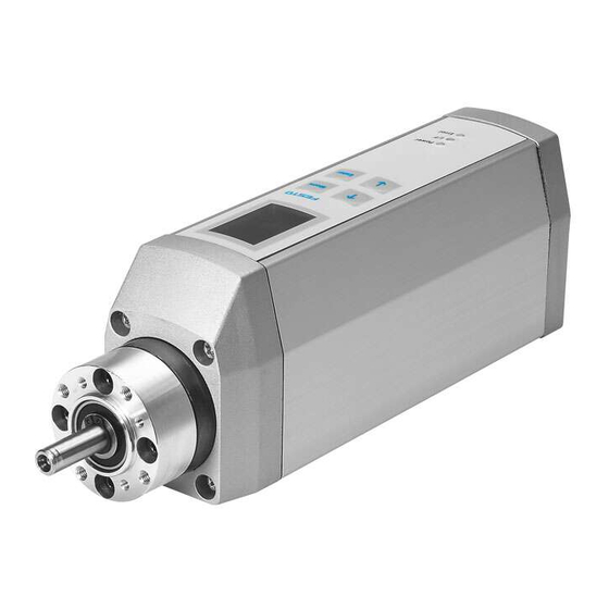
DC motor, planetary gear, encoder and inte- grated control electronics. Positioning functions are charac- terised by high torques at low speeds. The MTR-DCI has been optimised for use with Festo axes (e.g. DMES-... or DNCE-...). This description deals with the basic logic functions of the MTR-DCI and the Profibus interface. -
Page 10: Safety Instructions
Warning Faults in parameterisation can cause injury to human beings and damage to property. Only enable the controller once the axis system has been installed and parameterised by technically qualified staff. VIII Festo P.BE-MTR-DCI-PB-EN en 1209a... -
Page 11: Target Group
Service Please consult your local Festo Service or write to the follow- ing e-mail address if you have any technical problems: service_international@festo.com Scope of delivery... -
Page 12: Important User Instructions
... means that failure to observe this instruction may result in personal injury or damage to property. Note ... means that failure to observe this instruction may result in damage to property. Electrostatically sensitive devices: Incorrect handling can result in damage to components. Festo P.BE-MTR-DCI-PB-EN en 1209a... - Page 13 The bullet indicates activities which may be carried out in • any order. 1. Figures denote activities which must be carried out in the numerical order specified. – Hyphens are used to mark general lists of information. Festo P.BE-MTR-DCI-PB-EN en 1209a...
-
Page 14: Documentation For Mtr-Dci Motor Unit
P.BE-MTR-DCI-PB-EN PROFIBUS interface. P.BE-MTR-DCI-PB-FR P.BE-MTR-DCI-PB-IT P.BE-MTR-DCI-PB-ES P.BE-MTR-DCI-PB-SV Help system for software Festo Configuration Tool Function description of the Festo Con- help (contained in FCT figuration Tool (FCT) configuration soft- software) ware. Operating instructions Axes, e.g. Installation and commissioning DMES-... / DNCE-... -
Page 15: About The Version
MTR-DCI. You can find the version specifications as follows: – Hardware version and firmware version under “Device data” in the Festo Configuration Tool with active device connection to the MTR-DCI. – Firmware version on the control panel under [Diagnostic] [Software information]... -
Page 16: Product-Specific Terms And Abbreviations
All specification for forces/torques are defined in relation to the nominal motor torque (rela- tive to the nominal motor current). The actual force on the axis should be determined/checked during commissioning using external measuring devices and adjusted. Festo P.BE-MTR-DCI-PB-EN en 1209a... - Page 17 Changes in position are detected by the internal increment generator (optical encoder). With a known starting point, the actual posi- tion of the work load is calculated from the gear reduction and (where applicable) the feed constant. Festo P.BE-MTR-DCI-PB-EN en 1209a...
-
Page 18: Profibus-Specific Terms And Abbreviations
Bus cable between two terminating resistors. A bus segment contains maximum 32 stations. A PROFIBUS system consists of at least one bus segment with at least two stations. With the aid of repeaters further bus segments can be connected. Festo P.BE-MTR-DCI-PB-EN en 1209a... - Page 19 Response identifier (AK) Integral part of the parameter channel in response telegrams specify- ing the type of response from processing of a parameter. Response telegram Telegram sent from the slave to the master (slave response) XVII Festo P.BE-MTR-DCI-PB-EN en 1209a...
- Page 20 (sub-parameter number). User data Telegram data without protocol frame data. The length of the user data is defined in the configuration of the field bus slave. Tab. 0/4: Index of terms and abbreviations for PROFIBUS XVIII Festo P.BE-MTR-DCI-PB-EN en 1209a...
-
Page 21: System Overview
System overview Chapter 1 System overview Festo P.BE-MTR-DCI-PB-EN en 1209a... -
Page 22: Positioning With Electric Drives
......... 1-16 Festo handling and positioning profile (FHPP) ...... - Page 23 – Axis Fig. 1/1: Principle of positioning system with the MTR-DCI The motor unit MTR-DCI-...-DN with PROFIBUS allows posi- tioning of the connected linear or rotation axes in corres- pondence with the “Festo Handling and Positioning Profile” Festo P.BE-MTR-DCI-PB-EN en 1209a...
- Page 24 Moving in individual steps – Starting and stopping positioning pro- cedures while commissioning – Extended test functions e.g. status displays – Testing or demonstrating the position records Diagnostics/ – Reading and displaying diagnostics data – Service Festo P.BE-MTR-DCI-PB-EN en 1209a...
- Page 25 All the parameters in the controller are saved intern- ally in increments (inc, inc/s, inc/s ...) and are not converted until they are written in or read. Dimensions transmitted via PROFIBUS or RS232 are based on increments (for conversion see appendix A.4). Festo P.BE-MTR-DCI-PB-EN en 1209a...
- Page 26 Axis Linear or rotation axes as per catalogue Coupling with coupling For the axial attachment of Festo axes, e.g. type DMES-... or housing type DNCE-..., couplings and coupling housings are available as accessories. The motor unit is connected to the axis by means of a clamping connector in the coupling housing.
- Page 27 The set target posi- tion is transferred to the nominal value generator. This gener- ates a position nominal value for the position controller. The current settings for speed, acceleration, braking deceleration, etc. are taken into account for position control. Festo P.BE-MTR-DCI-PB-EN en 1209a...
- Page 28 (teach mode), [Settings][Position set] – Positioning travel for testing all positioning records in the positioning record table [Demo posit tab]. – Positioning travel for testing a certain positioning record in the positioning record table [Move posit set]. Festo P.BE-MTR-DCI-PB-EN en 1209a...
- Page 29 Software end position detection Observe the following: By the arrangement of the limit switches and, if neces- • sary, additionally by means of mechanical stops, make sure that the axis always lies within the permissible posi- tioning range. Festo P.BE-MTR-DCI-PB-EN en 1209a...
- Page 30 (e.g. as normally closed limit switches wired in series connection) – For disconnecting the ENABLE signal at the controller interface, – For switching off the load voltage as needed. 1-10 Festo P.BE-MTR-DCI-PB-EN en 1209a...
-
Page 31: Dimensional Reference System
If the target posi- tion of a positioning command lies outside of the software limits, the positioning command will not be processed and an error status will be set. 1-11 Festo P.BE-MTR-DCI-PB-EN en 1209a... - Page 32 Software end positions offsets: limit the permissible positioning range (effective stroke) Project zero point offset: distance from AZ Effective stroke: permitted travel range Nominal stroke of the axis used Tab. 1/1: Dimensional reference system 1-12 Festo P.BE-MTR-DCI-PB-EN en 1209a...
- Page 33 The direction in which the effective load moves is dependent on the gear unit, the spindle type (clockwise/anti-clockwise rotation), the prefix for the position specifications (+/-) and the active direction set: 1-13 Festo P.BE-MTR-DCI-PB-EN en 1209a...
- Page 34 1. System overview — — Factory setting of the active direction Reversal of direction by changing the active direction Fig. 1/3: Setting the active direction (on example MTR-DCI + DMES, axial gear, clockwise rotating spindle) 1-14 Festo P.BE-MTR-DCI-PB-EN en 1209a...
- Page 35 After successful reference travel, the drive stands at the axis zero point AZ. On initial start-up or following a change of ref- erence travel method the axis zero offset = 0; after reference travel the drive is then positioned at the reference point REF. 1-15 Festo P.BE-MTR-DCI-PB-EN en 1209a...
- Page 36 As the axis must not stand still at the stop, the axis zero point offset must be ≠ 0 (min. 0.25 mm). REF (-) — REF (+) Stop in a negative direction Stop in a positive direction Fig. 1/4: “Search for fixed stop” reference travel method 1-16 Festo P.BE-MTR-DCI-PB-EN en 1209a...
- Page 37 If the drive is at the reference switch at the start of reference travel, it will move in the opposite direction from the refer- ence switch. The drive then moves as usual to the axis zero point. 1-17 Festo P.BE-MTR-DCI-PB-EN en 1209a...
- Page 38 1. System overview Festo handling and positioning profile (FHPP) Tailored to handling and positioning tasks, Festo has devel- oped an optimised data profile, known as the “Festo Handling and Positioning Profile (FHPP)”. The FHPP enables uniform control and programming for Festo's various fieldbus systems and controllers.
- Page 39 The Record Select mode can be used to execute position set records saved in the MTR-DCI. For this purpose, up to 31 position sets are parameterised during commissioning either using the Festo Configuration Tool or taught via the control panel. Direct mode In the Direct mode the important positioning data are trans- ferred directly via the control bytes.
- Page 40 1. System overview 1-20 Festo P.BE-MTR-DCI-PB-EN en 1209a...
-
Page 41: Mounting
Mounting Chapter 2 Mounting Festo P.BE-MTR-DCI-PB-EN en 1209a... - Page 42 ........Festo P.BE-MTR-DCI-PB-EN en 1209a...
-
Page 43: General Information
Screws must be fitted accurately (otherwise threads will be damaged). – The specified torques must be observed. – The modules must not be offset from one another. – Contact surfaces must be clean (avoid contact faults). Festo P.BE-MTR-DCI-PB-EN en 1209a... -
Page 44: Dimensions Of The Motor Unit
2.5 ±0.3 ±0.2 ±0.2 ±0.3 ±0.3 ±0.3 Width 33.8 ±0.3 44.8 ±0.4 63.8 ±0.4 105.1 ±0.4 46.3 ±0.4 53.3 ±0.4 69.5 ±0.4 105.1 ±0.4 Depth M3: 7 / M4: 10 Tab. 2/1: Dimensions of the motor unit Festo P.BE-MTR-DCI-PB-EN en 1209a... -
Page 45: Mounting The Electric Axes
Make sure that you observe the maximum safe values for • the following variables. The point of reference for forces and torques is the centre of the shaft (L3 see Tab. 2/1). Festo P.BE-MTR-DCI-PB-EN en 1209a... - Page 46 The gear output torque or the motor unit is usually much lower, see Technical appendix A, Mech- anical data. MTR-DCI-62...-G22: In the start-up phase, torque peaks up to 37 Nm are possible at 20 A peak current. Tab. 2/2: Safe load for the gear shaft Festo P.BE-MTR-DCI-PB-EN en 1209a...
- Page 47 4 screws must be used. Size Thread / Tightening torque thread depth MTR-DCI-32-... 6 mm 1.2 Nm MTR-DCI-42-... 7 mm 1.2 Nm 10 mm 2.9 Nm MTR-DCI-52-... 10 mm 5.9 Nm MTR-DCI-62-... 10 mm 5.9 Nm Tab. 2/3: Tightening torques Festo P.BE-MTR-DCI-PB-EN en 1209a...
- Page 48 2. Mounting To mount Festo axes e.g. type DMES- or type DNCE-, coup- lings and coupling housings are available as accessories. The motor unit is connected to the axis by means of a clamp in the coupling housing. Additional motor flanges are not therefore necessary.
-
Page 49: Installation
Installation Chapter 3 Installation Festo P.BE-MTR-DCI-PB-EN en 1209a... - Page 50 ......... 3-18 Festo P.BE-MTR-DCI-PB-EN en 1209a...
-
Page 51: Overview Of Installation
Faulty pre-assembled lines may destroy the electronics and trigger unexpected movements of the motor. For cabling the electric components of the system, use • only the cables listed as accessories (see Tab. 3/2). Only in this way is proper system functioning ensured. Festo P.BE-MTR-DCI-PB-EN en 1209a... - Page 52 If non-assigned plug connectors are touched, there is a danger that damage may occur to the MTR-DCI or to other parts of the system as a result of ESD (electrostatic dis- charge). Place protective caps on unused terminals in order to prevent such discharges. Festo P.BE-MTR-DCI-PB-EN en 1209a...
- Page 53 3. Installation The plug connectors on the Festo cables listed in the follow- ing are of protection class IP54. Connection Cable Designation Length [m] Parameterisation Programming cable KDI-MC-M8-SUB-9-2.5 2.5 (max. 2.5) Reference switch Connecting cable KM8-M8-GSGD-... 0.5 / 1 / 2 / 5...
-
Page 54: Earthing
FE! Never connect one of the power supply connections (see • chapter 3.2, A1, A2) with FE or with the housing. This will avoid damaging the device and the impairing EMC protection functions. Festo P.BE-MTR-DCI-PB-EN en 1209a... -
Page 55: Power Supply
Make sure that the permitted voltage tolerance is not • exceeded. The tolerance must also be observed directly at the operating voltage connections on the MTR-DCI (see appendix A.1). Install external fuses (see Tab. 3/3). • Festo P.BE-MTR-DCI-PB-EN en 1209a... - Page 56 DC 24 V/ 10 A DC 48 V / 20 A power unit (stabilised) External fuse, 5 A slow-blowing 7 A slow-blowing 10 A slow-blowing 25 A slow-blowing secondary Tab. 3/3: Power supply units (for load voltage) and fuses Festo P.BE-MTR-DCI-PB-EN en 1209a...
-
Page 57: (Not For Mtr-Dci-32)
Black (2) MTR-DCI-32/42/52/62: POWER GND Cable colours with power supply cable KPWR-MC-1-SUB-9HC-... Do not connect the GND terminal to any housing, screen or functional earth (FE)! Tab. 3/4: Connecting the power supply to the motor unit Festo P.BE-MTR-DCI-PB-EN en 1209a... -
Page 58: Separate Supply With Load And Logic Voltage
Logic voltage failure If the logic voltage fails, the controller will switch off. For MTR-DCI-42/52/62: if the load voltage is still active, it will switch back on but will lose its reference position (= reset). 3-10 Festo P.BE-MTR-DCI-PB-EN en 1209a... -
Page 59: Serial Interface
Reserved for service staff – do not connect! The levels correspond to the RS232 standard and enable a data transmission rate of 9600 bit/s Tab. 3/5: Pin allocation for the serial interface on the MTR- 3-11 Festo P.BE-MTR-DCI-PB-EN en 1209a... - Page 60 PC systems, nor for use as a control interface. Use this terminal only for commissioning. • Remove the programming cable in continuous opera- • tion. Seal the terminal with the supplied protective cap (ISK- • M8). 3-12 Festo P.BE-MTR-DCI-PB-EN en 1209a...
-
Page 61: Input For External Reference Switch
When selecting the sensor, note that the accuracy of the • switchover point of the sensor determines the accuracy of the homing (reference) point. Suitable proximity switches from Festo can be found in the appendix A.2 “Accessories”. M8x1 socket Description... - Page 62 (sensor supply). Use of this connection as a power supply for other devices is not safe. The input for REF sensor signal complies in its electrical properties with the input specifications in the appendix “Technical data”. 3-14 Festo P.BE-MTR-DCI-PB-EN en 1209a...
-
Page 63: Connecting The Higher-Order Controller
DC 24 V at pin 7. Check whether there is any hazard for other fieldbus • stations. Observe the pin allocation in accordance with the as- • sembly instructions for the fieldbus adapter. 3-15 Festo P.BE-MTR-DCI-PB-EN en 1209a... -
Page 64: Fieldbus Cable
< 110 Ohm/km Core diameter: > 0.64 mm Core cross-section: > 0.34 mm Bus length Exact specifications on the bus length can be found in the next section and in the manuals for your control system. 3-16 Festo P.BE-MTR-DCI-PB-EN en 1209a... -
Page 65: Fieldbus Bit Rate And Fieldbus Length
1200 m 187.5 kBit/s 1000 m 500 kBit/s 400 m 1500 kBit/s 200 m 1.5 ... 12 MBit/s 100 m Tab. 3/8: Maximum fieldbus segment lengths for PROFIBUS- DP in dependence on the bit rate 3-17 Festo P.BE-MTR-DCI-PB-EN en 1209a... -
Page 66: Bus Termination
2. Fieldbus connection Continuation of the fieldbus or terminating resistor Supply of separate logic voltage For the pin allocation and connection specification, see the installation manual of the fieldbus adapter. 3-18 Festo P.BE-MTR-DCI-PB-EN en 1209a... -
Page 67: The Control Panel (Mtr-Dci-...-H2)
The control panel (MTR-DCI-...-H2) Chapter 4 The control panel (type MTR-DCI-...-H2) Festo P.BE-MTR-DCI-PB-EN en 1209a... - Page 68 ........4-22 Festo P.BE-MTR-DCI-PB-EN en 1209a...
- Page 69 FCT and the control panel can cause faults. Make sure that FCT and the control panel are not in use • at the same time. Note If necessary, remove the protective film from the display before commissioning. Festo P.BE-MTR-DCI-PB-EN en 1209a...
-
Page 70: Composition And Function Of The Control Panel
90° steps; see menu command [LCD adjust- ment]. The operating statuses are indicated visually by 3 LEDs (see also section 6.2). – Power: Power supply – I/F: Communication status (red), positioning status (green) – Error: Faults Festo P.BE-MTR-DCI-PB-EN en 1209a... - Page 71 After stop: display of current posi- tion; use <Menu> to return to the higher menu level. <- -> Scrolls within a menu level in order to select a menu command. EDIT Sets parameters. Tab. 4/1: Button function (overview) Festo P.BE-MTR-DCI-PB-EN en 1209a...
-
Page 72: The Menu System
When the power supply is switched on, the MTR-DCI auto- = 0.00 mm matically carries out an internal check. At first the display briefly shows the Festo logo, then changes to the status dis- HMI:off PB:none play. The status display shows the following information: <Menu>... - Page 73 Presetting for device control via the control panel (see section 4.6) LCD adjustment Rotates the display in steps of 90° May be password-protected Teach mode Control interface must be deactivated; see [HMI control] :HMI = on Tab. 4/3: Menu commands (overview) Festo P.BE-MTR-DCI-PB-EN en 1209a...
-
Page 74: Diagnostic] Menu
PROFIBUS diagnostic data [PROFIBUS Diag] – Firmware version for the MTR-DCI [SW information] Function Button <- -> You can scroll through the diagnos- tic data with the arrow keys. With <Menu> you can return to the Menu higher menu level. Festo P.BE-MTR-DCI-PB-EN en 1209a... - Page 75 Stroke limitation: software end position, negative x max Stroke limitation: software end position, positive Axis zero point offset feed Feed constant Unit of measurement depends on the measuring system set Not for axis type “Rotation drive” Festo P.BE-MTR-DCI-PB-EN en 1209a...
- Page 76 Fixed stop in positive direction – bl.pos Fixed stop in negative direction – bl.neg Reference switch in positive direction – sw.pos Reference switch in negative direction – sw.neg Gear e.g. 6.75 Gear reduction ratio of the MTR-DCI 4-10 Festo P.BE-MTR-DCI-PB-EN en 1209a...
- Page 77 GbDiagnosis Device-related diagnosis. – ON: If there is a fault, request for diagnosis will be sent. – OFF: If there is a fault, request for diagnosis will not be sent. 4-11 Festo P.BE-MTR-DCI-PB-EN en 1209a...
-
Page 78: Settings] Menu
Save the parameter settings permanently in EEPROM • with the [Save] menu command. Only then will the set- tings be retained even if the power supply is switched off or if there is a power failure. 4-12 Festo P.BE-MTR-DCI-PB-EN en 1209a... - Page 79 Teach mode for setting the axis parameters [Axis param] Description [Zero point] Offset of the axis zero point [Abs.min.pos] Stroke limitation: software limit switch, negative [Abs.max.pos] Stroke limitation: software limit switch, positive [Save...] Save parameters in EEPROM 4-13 Festo P.BE-MTR-DCI-PB-EN en 1209a...
- Page 80 Homing to (block positive) fixed stop, positive [Velocity v_sw] v_sw Speed for searching for the homing point [Velocity v_s0] v_s0 Speed for moving to the axis zero point [Save...] Save parameters in EEPROM 4-14 Festo P.BE-MTR-DCI-PB-EN en 1209a...
- Page 81 Save the parameter settings permanently in EEPROM • with the [Save] menu command. Only then will the set- tings be retained even if the power supply is switched off or if there is a power failure. 4-15 Festo P.BE-MTR-DCI-PB-EN en 1209a...
- Page 82 2. Confirm your entry with <Enter>. The next entry position will be displayed. 3. Repeat the entry for the remaining entry positions. Once the third digit has been confirmed, access via the control panel is enabled. 4-16 Festo P.BE-MTR-DCI-PB-EN en 1209a...
- Page 83 If the active password in the MTR-DCI is lost in spite of care being taken: If needed, the password can be deleted by entering a master password. In this case please contact your Festo Service partner. 4-17 Festo P.BE-MTR-DCI-PB-EN en 1209a...
-
Page 84: Positioning] Menu
Do not start a positioning run until the reference system • has been defined by homing. Note Note that position set records with speed v=0 or an invalid target position (-> fault TARGET POSITION OUT OF LIMIT) will not be executed. 4-18 Festo P.BE-MTR-DCI-PB-EN en 1209a... - Page 85 The positioning speed to the axis zero point, v_0. EMERG.STOP<Menu> Function EMERG. With<Menu> you can interrupt the positioning STOP procedure (> Error mode EMERG.STOP; con- Menu firm with <Enter>, then automatic return to the status display). 4-19 Festo P.BE-MTR-DCI-PB-EN en 1209a...
- Page 86 Pos 1 played: = 100.00 mm v = 20 mm/s – The active position set, Pos... = 90.00 mm EMERG.STOP<Menu> – The target position, x – The positioning speed, v – The current position, x 4-20 Festo P.BE-MTR-DCI-PB-EN en 1209a...
- Page 87 With <Enter> you can interrupt the “Position Enter STOP set table” positioning run [Demo posit tab] . The current positioning set will be executed before the axis stops. If you restart, the run will begin with record 0. 4-21 Festo P.BE-MTR-DCI-PB-EN en 1209a...
-
Page 88: Menu Command [Hmi Control]
Device control is carried out via the control interface of the MTR-DCI. Human Machine Interface Note Access to the MTR-DCI via HMI and FCT can be blocked via the fieldbus (“HMIAccess locked”). 4-22 Festo P.BE-MTR-DCI-PB-EN en 1209a... -
Page 89: Commissioning
Commissioning Chapter 5 Commissioning Festo P.BE-MTR-DCI-PB-EN en 1209a... - Page 90 ..........5-36 Festo profile for handling and positioning (FHPP) .....
- Page 91 ..........5-81 Festo P.BE-MTR-DCI-PB-EN en 1209a...
-
Page 92: Commissioning Procedure
MTR-DCI Please note the following: Control by the FCT must not be activated while the drive • is in motion or when control is being carried out via field- bus. Festo P.BE-MTR-DCI-PB-EN en 1209a... - Page 93 2. Carry out parameterising and commissioning with the control panel or the FCT, as described in the following chapters or in the FCT/plugin help. 3. In order to complete commissioning note the instructions for operation in the FCT/plugin help and in section 5.9. Festo P.BE-MTR-DCI-PB-EN en 1209a...
-
Page 94: Commissioning With The Control Panel (Only Mtr-Dci
[HMI = on]. The HMI control actual status of the ENABLE control bit then has no effect. LCD adjustment Select [HMI control] = “on” and then OK <Enter>. • Festo P.BE-MTR-DCI-PB-EN en 1209a... - Page 95 Set PROFIBUS address. 5.2.7 Tab. 5/1: Commissioning (overview) In order to restore the default settings you can, if necessary, delete the EEPROM directly via the serial interface with the CI command 20F1h (Data memory control) (see appendix B.2.2). Festo P.BE-MTR-DCI-PB-EN en 1209a...
-
Page 96: Selecting The Axis Type
5. Commissioning 5.2.1 Selecting the axis type } Settings 1. Select your axis type: Axis type Type DMES... – Festo positioning axis [Type DMES-...] Type DNCE... Rotation drive – Festo electrical drive [Type DNCE-...] User config – Any axis of rotation [Rotation drive] –... -
Page 97: Setting Homing Parameters
If the motor current is too low, homing cannot be carried out or the unit may detect a stop incorrectly. – The set required speed cannot be reached if current limitation is too great. Festo P.BE-MTR-DCI-PB-EN en 1209a... - Page 98 2) Due to maximum current limitation the value does not rise further. Tab. 5/3: Current limitation Positioning axis DMES-... can execute the reference travel with the factory-set current limiter (150 % of the rated motor current). The current limiter need not be changed. 5-10 Festo P.BE-MTR-DCI-PB-EN en 1209a...
- Page 99 3. Save the parameter settings with the [Save] menu com- mand. Only then will the settings be retained even if the power supply is switched off or if there is a power failure. 5-11 Festo P.BE-MTR-DCI-PB-EN en 1209a...
-
Page 100: Carrying Out Homing
REF (Fig. 5/1 1 ). The drive then moves at speed v_s0 to the axis zero point AZ (Fig. 5/1 2 ). Move to the homing point REF Move to the axis zero point AZ Fig. 5/1: Homing (example: fixed stop, negative) 5-12 Festo P.BE-MTR-DCI-PB-EN en 1209a... - Page 101 After successful homing the drive will be at the axis zero point AZ. With first commissioning, the offset of the axis zero point = 0; after homing the drive then stands at the homing point REF. 5-13 Festo P.BE-MTR-DCI-PB-EN en 1209a...
- Page 102 If necessary, position the drive in Teach mode so that, • when viewed in terms of the search direction, it is in front of the stop or reference switch at the start. Repeat the homing run. • 5-14 Festo P.BE-MTR-DCI-PB-EN en 1209a...
-
Page 103: Teaching The Axis Zero Point Az And The Software End Positions
(if applicable) the project zero point and the target posi- tions in the position set table. Note that these values move together with the axis zero point AZ. Teach the software end positions, project zero point and • the target positions again if needed. 5-15 Festo P.BE-MTR-DCI-PB-EN en 1209a... - Page 104 Note The project zero point PZ can only be set via FCT or PNU 500 / CI object 21F4 5-16 Festo P.BE-MTR-DCI-PB-EN en 1209a...
-
Page 105: Teaching Position Set Records
Accept the position reached with OK <Enter>. The • setting of the target position and the positioning mode will then take effect in the drive. 4. Set the speed: Select [Velocity]. • 5-17 Festo P.BE-MTR-DCI-PB-EN en 1209a... - Page 106 If necessary, insert an absolute position set or a homing run into the positioning cycle, in order to cor- rect deviations. 5-18 Festo P.BE-MTR-DCI-PB-EN en 1209a...
-
Page 107: Test Run
In the [Demo posit tab] positioning cycle, all position set records 1...31 in the position set table will be executed one after the other. If the position set table contains a 5-19 Festo P.BE-MTR-DCI-PB-EN en 1209a... - Page 108 Check the positioning behaviour. • Check the position details displayed. • 5. If necessary, optimise the settings for position sets, and also (if needed) for the points of reference and the work- ing range. 5-20 Festo P.BE-MTR-DCI-PB-EN en 1209a...
-
Page 109: Setting Profibus Addresses
3. Set the desired address with the arrow buttons. PROFIBUS address 4. Accept the address with OK <Enter>. The set address becomes effective immediately and is ESC <Menu> saved against network failure. EDIT <--> SAVE <Enter> 5-21 Festo P.BE-MTR-DCI-PB-EN en 1209a... -
Page 110: Commissioning With Fct
5. Commissioning Commissioning with FCT The Festo Configuration Tool (FCT) is the software platform for configuring and commissioning different components and devices from Festo. The FCT consists of the following components: – A framework as program start and entry point with uni- form project and data management for all supported types of devices. -
Page 111: Installing The Fct
The MTR-DCI plugin is installed on your PC together with the FCT's installation program. 1. Close all programs. 2. Place the Festo Configuration Tool CD in your CD ROM drive. If Auto Run is activated on your system, the installa- tion will start automatically and you can omit steps 3 and 4. -
Page 112: Procedure
2. Start the FCT: Double-click the FCT icon on the desktop. – or – Select the entry [Festo Software] [Festo Configuration Tool] in the Windows [Start] menu. 3. Create a project in the FCT or open an existing project. Add a device to the project with the MTR-DCI plugin. - Page 113 Further information can be found in the plugin help: Com- mand [Help] [Contents of installed plugins] [Festo (manufac- turer name)] [MTR-DCI (plugin name)], e.g.: – For describing the dialogues of the “Device MTR-DCI”...
-
Page 114: Overview Of Commissioning On The Profibus
1. Set the PROFIBUS address on the MTR-DCI: On the control panel (only with MTR-DCI-...-H2, see • Section 5.2.7), or With the Festo Configuration Tool (see FCT help). • Permitted address range: 0 ... 125 (in some cases limited by the DP master used). -
Page 115: Configuration
Reference sources The enclosed documentation CD contains GSD files and icon files for the MTR-DCI in the “PROFIBUS” folder. Current GSD files and icon files can be found on the Festo Internet pages at: – www.festo.com/download/... -
Page 116: I/O Configuration
“Festo handling and positioning profile standard” GSD entry as “FHPP Standard” 8 bytes of I/O data, consistent transmission – “Festo handling and positioning profile with parameter channel” GSD entry as “FHPP Standard + FPC” 2 x 8 bytes of I/O data, consistent transmission 5-28 Festo P.BE-MTR-DCI-PB-EN en 1209a... -
Page 117: Configuration With Step
1) If you copy the GSD files when the Simatic Manager has already been started, you can update the hardware catalogue with the command [Options] [Update Catalog]. Tab. 5/5: Folder for GSD and icon files in STEP 7 5-29 Festo P.BE-MTR-DCI-PB-EN en 1209a... - Page 118 In order to add the MTR-DCI: 1. Drag the station type “Festo MTR-DCI” (DP-V0 and DP-V1) or “Festo MTR-DCI DP-V0” ( 3 ) out of the hardware cata- logue and onto the PROFIBUS line ( 1 ) of the DP master system (drag &...
- Page 119 5. Commissioning PROFIBUS line Festo MTR-DCI entry from GSD file Icon for MTR-DCI Fig. 5/2: Station selection STEP 7 5-31 Festo P.BE-MTR-DCI-PB-EN en 1209a...
- Page 120 In order to configure the slave properties of the MTR-DCI: 1. Open the available modules (configurations) in the hard- ware catalogue under [Festo MTR-DCI ...]. 2. Then drag the desired configuration (see section 5.5.2) with the mouse into the appropriate line under Slot/DP identifier.
- Page 121 5. Commissioning DP identifiers Modules (configurations) I/O address range Fig. 5/3: Configuring the slave properties When the configuration is concluded, transfer the data to the master. 5-33 Festo P.BE-MTR-DCI-PB-EN en 1209a...
-
Page 122: Startup Parameter Assignment
= 1: In the case of a fault, diagnosis will not be requested by the master Tab. 5/6: Configuration of the data exchange (connection settings) Fig. 5/4: Properties of DP slave – parameter assignment 5-34 Festo P.BE-MTR-DCI-PB-EN en 1209a... -
Page 123: Response Monitoring
FREEZE, SYNC and CLEAR_DATA are supported by the MTR- DCI in accordance with EN 50170. The method of accessing these commands depends on the controller used. Please refer to the documentation for your control system. 5-35 Festo P.BE-MTR-DCI-PB-EN en 1209a... -
Page 124: Overview Of Control And Parameter Assignment Methods
Control with DPV0 takes place via the 8 cyclical control and status bytes, see section 5.7.2. Parameter assignment Parameter assignment with DPV0 takes place via the Festo parameter channel (FPC, further 8 I/O bytes), see section B.1.1. 5.6.2 DPV1 Parameter assignment Parameter assignment with DPV1 takes place via the para- meter channel as per PROFIdrive V3.1. -
Page 125: Festo Profile For Handling And Positioning (Fhpp)
5. Commissioning Festo profile for handling and positioning (FHPP) The MTR-DCI supports the Festo handling and positioning profile FHPP (see also section 1.6). 5.7.1 Supported operation modes The operation modes differ as regards the contents and meaning of the cyclical I/O data and in the functions which can be accessed in the MTR-DCI. - Page 126 PLC and the MTR-DCI is necessary. Force mode Alternatively, nominal values can be specified in Direct mode relative to the nominal motor current. This gives a torque and, in the case of linear drives, a force (= force control). 5-38 Festo P.BE-MTR-DCI-PB-EN en 1209a...
-
Page 127: Composition Of The Cyclical I/O Data
In the cyclical data a further 8 input bytes and 8 output bytes are permitted for transferring parameters in accordance with the FPC protocol. The acyclical data channel of the PROFIBUS (DPV1) is also supported. 5-39 Festo P.BE-MTR-DCI-PB-EN en 1209a... - Page 128 Byte 2 Byte 3 Byte 4 Byte 5 Byte 6 Byte 7 Byte 8 O data Reserved Subindex Request identifier Parameter value + parameter number I data Reserved Subindex Response identifier Parameter value + parameter number 5-40 Festo P.BE-MTR-DCI-PB-EN en 1209a...
- Page 129 SDIR FUNC FAST XLIM VLIM CONT COM2 COM1 (Direct Stroke Speed Control mode feed- Absolute mode limit re- limit re- back (position, / Relative only) ached ached force/torque, ...) – : reserved. 5-41 Festo P.BE-MTR-DCI-PB-EN en 1209a...
- Page 130 Control byte 1 (CCON) is used to control all states which must be available in all operation modes. The cooperation of the control bits can be found under the description of the drive functions in section 5.8. 5-42 Festo P.BE-MTR-DCI-PB-EN en 1209a...
- Page 131 In the “Halt” status, a signal edge causes the positioning CLEAR ing path task to be deleted and transfers the system to the “Ready” status. – Reserved, must be at 0. – CPOS controls the positioning sequences as soon as the drive is enabled. 5-43 Festo P.BE-MTR-DCI-PB-EN en 1209a...
- Page 132 Preselection of velocity in % of the maximum velocity Control bytes 5... 8 (nominal value 2) – Direct mode Description B0...B31 Position, force, ... Preselection of the position in increments or of the force in % of nominal current 5-44 Festo P.BE-MTR-DCI-PB-EN en 1209a...
- Page 133 Control byte 3 (record number) – Record Select Description B0 ... B7 Record number Preselection of position set record number for Record Select Control bytes 4... 8 – Record Select Description B0 ... B7 – Reserved (= 0) 5-45 Festo P.BE-MTR-DCI-PB-EN en 1209a...
- Page 134 = 0: Device control by PLC/fieldbus LOCK = 1: Device control by FCT/HMI (PLC control is locked) Display = 00: Record Select (Standard) OPM1 Operating Mode = 01: Direct mode = 10: Reserved = 11: Reserved OPM2 5-46 Festo P.BE-MTR-DCI-PB-EN en 1209a...
- Page 135 = 0: After MC, axis remains in tolerance window STILL = 1: After MC, axis is outside tolerance window Axis is referenced = 0: Homing must be carried out = 1: Home information exist, homing does not need to be carried out 5-47 Festo P.BE-MTR-DCI-PB-EN en 1209a...
- Page 136 B0 ... B7 Record Status Byte For allocation see SDIR for Direct mode Status bytes 5 ... 8 (Position) – Record Select Description B0...B31 Position, ... Feedback of position for Record Select: – Position in increments 5-48 Festo P.BE-MTR-DCI-PB-EN en 1209a...
- Page 137 Description B0 ... B7 Torque In % of the nominal current (see 5.7.3, point 7) Status bytes 5 ... 8 (actual value 2) – Direct mode Description B0...B31 Position, ... Feedback of position in increments 5-49 Festo P.BE-MTR-DCI-PB-EN en 1209a...
-
Page 138: Examples Of Control And Status Bytes
F: Edge positive Tab. 5/8: Control and status bytes for “Device control active” Description for 0. Ensuring device control: Device control via the control panel or the Festo Configuration Tool has been activated. To control the MTR-DCI via the PROFIBUS interface, device control by FCT/HMI must first be deactivated. - Page 139 } Step 1.3 Enable drive in Record Select mode. } Homing: example 4, Tab. 5/12. If there are faults after switching on or after setting CCON.B0 (ENABLE): } Fault handling: see example 3, Tab. 5/11. 5-51 Festo P.BE-MTR-DCI-PB-EN en 1209a...
- Page 140 CCON.B5 = 1 (LOCK). } Step 2.3 Enable drive in Direct mode. } Homing: example 4, Tab. 5/12. If there are faults after switching on or after setting CCON.B0 (ENABLE): } Fault handling: see example 3, Tab. 5/11. 5-52 Festo P.BE-MTR-DCI-PB-EN en 1209a...
-
Page 141: Fault Handling
CLEAR TEACH JOGN JOGP START HALT Byte 2 STILL MOV TEACH HALT (ENABLE) CPOS x SPOS x 0: 0-signal; 1: 1-signal; x: not relevant (any); F: Edge positive Tab. 5/11: Control and status bytes for “Fault handling” 5-53 Festo P.BE-MTR-DCI-PB-EN en 1209a... - Page 142 Acknowledge malfunction with negative edge at CCON.B0 (ENABLE). } Malfunction bit SCON.B3 (FAULT) or SCON.B2 (WARN) are reset } SPOS.B2 (MC) is set } Reestablish operating status (see examples 1, Tab. 5/9 and 2, Tab. 5/10) 5-54 Festo P.BE-MTR-DCI-PB-EN en 1209a...
- Page 143 Movement of the axis is shown with SPOS.B4 (MOV, Axis is moving). After successful homing, SPOS.B2 (MC, Motion Com- plete) and SPOS.B7 (REF) are set. If there are faults during homing: } Fault handling: see example 3, Tab. 5/11. 5-55 Festo P.BE-MTR-DCI-PB-EN en 1209a...
- Page 144 Byte 5...8 Reserved Byte 5...8 Position – Reserved Actual position (increments) tual posi- tion 0: 0-signal; 1: 1-signal; x: not relevant (any); F: Edge positive Tab. 5/13: Control and status bytes for “Positioning by Record Select” 5-56 Festo P.BE-MTR-DCI-PB-EN en 1209a...
- Page 145 Movement of the axis is shown with SPOS.B4 (MOV, Axis is moving). At the end of the positioning task, SPOS.B2 (MC, Mo- tion Complete) is set. If there are faults during positioning: } Fault handling: see example 3, Tab. 5/11. 5-57 Festo P.BE-MTR-DCI-PB-EN en 1209a...
- Page 146 HALT CPOS x SPOS 1 0: 0-signal; 1: 1-signal; x: not relevant (any); F: Edge positive S: Positioning condition: 0= absolute; 1 = relative Tab. 5/14: Control and status bytes for “Positioning by Direct Mode” 5-58 Festo P.BE-MTR-DCI-PB-EN en 1209a...
- Page 147 Movement of the axis is shown with SPOS.B4 (MOV, Axis is moving). At the end of the positioning task, SPOS.B2 (MC, Motion Complete) is set. If there are faults during positioning: } Fault handling: see example 3, Tab. 5/11. 5-59 Festo P.BE-MTR-DCI-PB-EN en 1209a...
- Page 148 – CLEAR TEACH JOGN JOGP START HALT Byte 2 STILL MOV TEACH HALT reached) CPOS x SPOS 1 Byte 3 FUNC FAST – CONT COM2 COM1 Byte 3 FUNC FAST CONT COM2 COM1 CDIR SDIR 5-60 Festo P.BE-MTR-DCI-PB-EN en 1209a...
- Page 149 Prepare Force mode: set bit CDIR.B1 COM1, and set bit CDIR.B5 XLIM depending on the desired level of stroke limitation. Start the job with CPOS.B1 START. The start is con- firmed with SPOS.B1 (acknowledge start) as long as CPOS.B1 (START) is set. 5-61 Festo P.BE-MTR-DCI-PB-EN en 1209a...
- Page 150 If there are faults during Force mode: See example 3, Table 5/13 Fault handling. Note In Force mode, the nominal value can only be changed after the last specification is reached (MC), by means of a new start pulse edge. 5-62 Festo P.BE-MTR-DCI-PB-EN en 1209a...
-
Page 151: Drive Functions
Lower software end position Effective stroke Upper software end position Nominal stroke TP, AP Target/actual position Target/actual position offset Example for the homing method: Fixed stop, negative Tab. 5/16: Dimensional reference system See also section 1.5. 5-63 Festo P.BE-MTR-DCI-PB-EN en 1209a... -
Page 152: Homing
1. Searching for the reference point in accordance with the configured method. 2. Moving from the reference point to the axis zero point (axis zero point offset). 3. Setting at axis zero point: Current position = 0 – project zero point offset (i.e. –PZ). 5-64 Festo P.BE-MTR-DCI-PB-EN en 1209a... - Page 153 Search for positive stop. The point found is the reference position. As the axis must not stand still at the stop, the axis zero point offset must be ≠ 0. For detailed description of homing methods see section 5.2.2. Tab. 5/19: Overview of homing methods 5-65 Festo P.BE-MTR-DCI-PB-EN en 1209a...
-
Page 154: Jog Mode
4. If the drive reaches a software end position, it will stop automatically. The software end position is not exceeded; the distance for stopping is accounted for according to the ramp set. Here too, the system does not leave Jogging mode until Jogging = 0. 5-66 Festo P.BE-MTR-DCI-PB-EN en 1209a... - Page 155 CPOS.B4 = positive edge: jogging negative (backwards) Feedback SPOS.B4 = 1: drive is moving SPOS.B2 = 0: (Motion Complete) Requirements Device control by PLC/fieldbus Controller must be in status “Operation enabled” Tab. 5/20: Parameters involved in jogging mode 5-67 Festo P.BE-MTR-DCI-PB-EN en 1209a...
-
Page 156: Teaching Via Fieldbus
Position set record after control byte 3 – Direct mode: Position set record after PNU=400 Axis zero point Project zero point Lower software end position Upper software end position Tab. 5/21: Overview of teach targets 5-68 Festo P.BE-MTR-DCI-PB-EN en 1209a... - Page 157 SPOS.B3 = 1: Value transferred Requirement Device control by PLC/fieldbus Controller must be in status “Operation enabled” Teach function is made possible in the Festo Configuration Tool by special functions. Tab. 5/22: Parameters involved for teaching 5-69 Festo P.BE-MTR-DCI-PB-EN en 1209a...
-
Page 158: Record Select: Executing A Position Set Record
4. When the record is concluded, MC (SPOS.B2) is set. Possible causes of faults: – Homing has not been carried out – The target position and/or the preselect position cannot be reached – Invalid record number 5-70 Festo P.BE-MTR-DCI-PB-EN en 1209a... - Page 159 As soon as “Acknowledge Start” is A currently running positioning task detected by the PLC, it can set “Start” can be stopped with “Stop”. back to 0. Fig. 5/7: Flow diagram for “start/stop record” 5-71 Festo P.BE-MTR-DCI-PB-EN en 1209a...
- Page 160 Record is stopped with “Halt,” actual Rising edge on “Start” starts record N record number N is retained, “Motion again, “Confirm Halt” is set Complete” remains reset Fig. 5/8: Flow diagram for “stop record with Hold and continue” 5-72 Festo P.BE-MTR-DCI-PB-EN en 1209a...
- Page 161 Axis is moving SPOS.B4 (MOV) Actual record N - 1 N + 1 number in input data Stop record Clear remaining positioning path Fig. 5/9: Flow diagram for “stop record with Halt and clear remaining positioning path” 5-73 Festo P.BE-MTR-DCI-PB-EN en 1209a...
- Page 162 SPOS.B1 = positive edge: Acknowledge start SPOS.B4 = 1: Drive is moving Requirements Device control by PLC/fieldbus Controller must be in “Operation enabled” status. A valid record number is active Tab. 5/23: Parameters involved for Record Select 5-74 Festo P.BE-MTR-DCI-PB-EN en 1209a...
-
Page 163: Direct Mode: Specification Of A Position Or Force
3. After the start you must wait for MC before a new start can be made. 4. When the nominal position is reached, MC (SPOS.B2) is set. 5-75 Festo P.BE-MTR-DCI-PB-EN en 1209a... - Page 164 (the current position), and the MC signal is set. Possible causes of faults: – Homing not carried out. – Target position cannot be reached or lies outside the soft- ware end positions. 5-76 Festo P.BE-MTR-DCI-PB-EN en 1209a...
- Page 165 Fig. 5/10: Starting the positioning task The sequence of the remaining control and status bits as well as the functions Halt and Stop react as for the Record Select function; see Fig. 5/7, Fig. 5/8 and Fig. 5/9. 5-77 Festo P.BE-MTR-DCI-PB-EN en 1209a...
- Page 166 All specification for forces/torques are de- fined in relation to the nominal motor torque (relative to the nominal motor current). The actual force on the axis should be determined/checked during commissioning using external measuring devices and adjusted. 5-78 Festo P.BE-MTR-DCI-PB-EN en 1209a...
-
Page 167: Standstill Monitoring
Adjustment time (po- sition window time) Standstill monitoring time Fig. 5/11: Standstill monitoring Standstill monitoring cannot be switched on or off explicitly. It becomes inactive when the standstill position window is set to the value “0”. 5-79 Festo P.BE-MTR-DCI-PB-EN en 1209a... - Page 168 SPOS.B2 = positive edge: Motion Complete Feedback SPOS.B6 = 1: Drive has moved out of standstill position window. Requirement Device control by PLC/fieldbus Controller in “operation enabled” state Tab. 5/25: Parameters involved in standstill monitoring 5-80 Festo P.BE-MTR-DCI-PB-EN en 1209a...
-
Page 169: Notes On Operation
The reference position will then be lost. Carry out homing again. • Note When the power supply is switched off, wait for approx. • 5 seconds before switching the device on again. 5-81 Festo P.BE-MTR-DCI-PB-EN en 1209a... - Page 170 When movement is made to the end positions with a heavy load, blockage may occur in the end positions. Note Any functions implemented for the purposes of EMERGENCY-STOP procedures must also be taken into account in the control programs 5-82 Festo P.BE-MTR-DCI-PB-EN en 1209a...
- Page 171 HMI password protection with the MTR-DCI-...H2 (3 characters, see section 4.4). Care and maintenance The motor units do not require maintenance during their spe- cified service life. Follow the maintenance instructions for the accessory components. 5-83 Festo P.BE-MTR-DCI-PB-EN en 1209a...
- Page 172 5. Commissioning 5-84 Festo P.BE-MTR-DCI-PB-EN en 1209a...
-
Page 173: Diagnostics And Fault Display
Diagnostics and fault display Chapter 6 Diagnostics and fault display Festo P.BE-MTR-DCI-PB-EN en 1209a... - Page 174 Diagnosis via parameter channel ........6-18 Festo P.BE-MTR-DCI-PB-EN en 1209a...
-
Page 175: Overview Of Diagnostic Options
Device-related diagnosis in ac- Diagnosis via the PROFIBUS-DP service Section 6.5 cordance with IEC 61158-6 Type 3 “GetDiag” Parameter assignments Control panel: in [Diagnostic] menu Section 4.3 Plugin help Tab. 6/1: Diagnostic information by type Festo P.BE-MTR-DCI-PB-EN en 1209a... - Page 176 Device-related diagnosis – Diagnosis via FHPP status bytes SCON and SPOS PROFIBUS via – Detailed diagnos- Sections 6.4 and Expanded access to diagnostic data, is via fieldbus e.g. diagnostic memory. Tab. 6/2: Diagnostic information by access Festo P.BE-MTR-DCI-PB-EN en 1209a...
-
Page 177: Led Status Displays
Tab. 6/3: “Power” LED Fault display ERROR Status Fault. The motor unit is not ready to operate. Warning. Check cause and rectify if necessary; see section 6.3. Flashing No internal fault reported. Tab. 6/4: “Error” LED Festo P.BE-MTR-DCI-PB-EN en 1209a... - Page 178 Data exchange active – Normal operating status. Address not parameterised – Invalid bus address set. Flashing red fast (5Hz) Waiting for connection Flashing red slowly (1Hz) Two-colour LED Tab. 6/6: LED “I/F” – red PROFIBUS LED Festo P.BE-MTR-DCI-PB-EN en 1209a...
-
Page 179: Fault Messages
(checksum fault) Fault TARGET POSITION Position outside 0x0080 FAULT OUT OF LIMIT! software end positions Warning ILLEGAL RECORD Invalid record no. 0x0100 FLASH- WARN WARNING See object 2FF1/00 For FHPP status bytes, see section 5.7.2 Festo P.BE-MTR-DCI-PB-EN en 1209a... -
Page 180: Description Of Faults And Warnings
The menu command [Move position set] is not = 0. Please set being executed because the positioning speed of the position set record is v = 0. Modify the parameter assignment or select a different position set record. Festo P.BE-MTR-DCI-PB-EN en 1209a... - Page 181 With <Enter> on the control panel – Via fieldbus with a falling edge on the ENABLE signal – Via fieldbus with a rising edge on the RESET signal CCON.B3 – With the “Reset error” button in the Festo Configuration Tool Festo P.BE-MTR-DCI-PB-EN en 1209a...
- Page 182 6. Diagnostics and fault display Fault Possible cause HARDWARE ERROR Device error, e.g. EEPROM defective. • Contact Festo Service. HOMING ERROR Fault during homing Possible causes: – Homing interrupted – Reference switch defective • If necessary, check the function of the reference switch.
- Page 183 • Check the following: – The software end positions – The target position – The basis of the target position (absolute or relative) PROFIBUS-INIT-ERROR PROFIBUS initialisation fault – Hardware fault • Servicing required. Tab. 6/8: Fault messages 6-11 Festo P.BE-MTR-DCI-PB-EN en 1209a...
-
Page 184: Diagnostic Memory
– Read will always be answered with value = 0. Number of valid entries in the diagnostic memory. *) Outgoing fault = time when the fault was acknowledged (= reset). Tab. 6/10: Diagnostic memory: configuration 6-12 Festo P.BE-MTR-DCI-PB-EN en 1209a... - Page 185 100 ... 109 Motor runtime Motor runtime: undervoltage, overtemperature, ... 110 ... 119 – Reserved Tab. 6/11: Overview of fault numbers A detailed description of the warnings and faults can be found in section 6.3.2. 6-13 Festo P.BE-MTR-DCI-PB-EN en 1209a...
-
Page 186: Diagnosis Via Profibus-Dp
IEC 61158-6 Type 3. Note The “identifier- or channel-related” diagnosis listed in IEC 61158-6 Type 3 is not supported. How to request the DP diagnosis for a slave is described in the manual for your DP master. 6-14 Festo P.BE-MTR-DCI-PB-EN en 1209a... - Page 187 Byte 12: subsidiary version Device-related diagnosis 3: Fault number; see section 6.3, Tab. 6/8. fault number The MTR-DCI permanently enters the value “10” in this octet. E.g. “0x02 0x01” Z V1.02 Tab. 6/12: DP diagnosis (device-related diagnosis) 6-15 Festo P.BE-MTR-DCI-PB-EN en 1209a...
- Page 188 Is set by the MTR-DCI when a new fault occurs (new fault message). Is set to 1 in the DP master when the response sent by the slave cannot be interpreted. Tab. 6/13: Diagnostic bits of station status 1 6-16 Festo P.BE-MTR-DCI-PB-EN en 1209a...
- Page 189 Tab. 6/14: Diagnostic bits of station status 2 Station status 3 Station status_3 Meaning Explanation 0...6 – Reserved Diag.Ext_Diag_Overflow Is always logical 0 (set by the MTR-DCI). Tab. 6/15: Diagnostic bits of station status 3 6-17 Festo P.BE-MTR-DCI-PB-EN en 1209a...
-
Page 190: Diagnosis Via Parameter Channel
6. Diagnostics and fault display Diagnosis via parameter channel The Festo parameter channel or the parameter channel as per PROFIdrive (see section 5.6) offers the following methods of accessing diagnostic information (see PNU 201 to 205, section B.1.8): – Current device fault (see also faults and warnings, section 6.3) -
Page 191: A. Technical Appendix
Technical appendix Appendix A Technical appendix Festo P.BE-MTR-DCI-PB-EN en 1209a... - Page 192 Converting the units of measurement ....... A-13 Festo P.BE-MTR-DCI-PB-EN en 1209a...
-
Page 193: Technical Data
1 Shock As per DIN/IEC 68/EN 60068 Part 2-27, severity level 1 Electromagnetic compatibility (EMC) See declaration of conformity (www.festo.com) Protection against electric shock By means of PELV power circuit (protection against direct and indirect contact (Protected Extra-Low Voltage) - Page 194 – Efficiency – 0.75 Mass moment of inertia – [kg cm – – – Rotor [kg cm 0.022 – Gearing Product weight [kg] – – – For permitted loading of gear shaft, see chapter 2, Tab. 2/2 Festo P.BE-MTR-DCI-PB-EN en 1209a...
- Page 195 Logic DC 24 V ±10 % Nominal current 0.73 A 6.19 A (load) Peak current (load) 2.1 A 3.8 A 7.7 A 20 A Nominal current 0.15 A (logic) *) Only relevant with separated voltage supply. Festo P.BE-MTR-DCI-PB-EN en 1209a...
-
Page 196: Accessories
E.g. of binder: No. – voltage supply taining protection class IP 08-2424-010-000 54 if separate power sup- ply not used User documentation in paper form German P.BE-MTR-DCI-PB-DE English P.BE-MTR-DCI-PB-EN French P.BE-MTR-DCI-PB-FR Italian P.BE-MTR-DCI-PB-IT Spanish P.BE-MTR-DCI-PB-ES Swedish P.BE-MTR-DCI-PB-SV Festo P.BE-MTR-DCI-PB-EN en 1209a... -
Page 197: Motor Characteristic Curves
A. Technical appendix Motor characteristic curves Drive output torque of gear shaft M [Nm] Current I [A] Recommended operation Impermissible range Overload range Festo P.BE-MTR-DCI-PB-EN en 1209a... - Page 198 A. Technical appendix MTR-DCI-32...-G7 n [rpm] I [A] M [Nm] MTR-DCI-32...-G14 n [rpm] I [A] M [Nm] Fig. A/1: Motor characteristic curves MTR-DCI-32... Festo P.BE-MTR-DCI-PB-EN en 1209a...
- Page 199 A. Technical appendix MTR-DCI-42...-G7 n [rpm] I [A] M [Nm] MTR-DCI-42...-G14 n [rpm] I [A] M [Nm] Fig. A/2: Motor characteristic curves MTR-DCI-42... Festo P.BE-MTR-DCI-PB-EN en 1209a...
- Page 200 A. Technical appendix MTR-DCI-52...-G7 n [rpm] I [A] M [Nm] n [rpm] MTR-DCI-52...-G14 I [A] M [Nm] Fig. A/3: Motor characteristic curves MTR-DCI-52... A-10 Festo P.BE-MTR-DCI-PB-EN en 1209a...
- Page 201 A. Technical appendix MTR-DCI-62...-G7 I [A] n [rpm] M [Nm] MTR-DCI-62...-G14 n [rpm] I [A] M [Nm] Fig. A/4: Motor characteristic curves MTR-DCI-62... A-11 Festo P.BE-MTR-DCI-PB-EN en 1209a...
- Page 202 A. Technical appendix MTR-DCI-62...-G22 n [rpm] I [A] M [Nm] Fig. A/5: Motor characteristic curves MTR-DCI-62... A-12 Festo P.BE-MTR-DCI-PB-EN en 1209a...
-
Page 203: Converting The Units Of Measurement
– “feed”: feed constant (dependent on the axis type). – “enc”: encoder resolution = physical measuring steps per motor revolution. On the MTR-DCI: pulse quadruplication by digital interpolation. – “gear”: gear reduction. A-13 Festo P.BE-MTR-DCI-PB-EN en 1209a... - Page 204 27906.602076 MTR-DCI-42... 5400 137160 (+DMES-25) -G14 10986.851211 27906.602076 MTR-DCI-52... 3375 85725 (+DMES-40) -G14 6866.782007 17441.626298 MTR-DCI-62... 2250 57150 (+DMES-63) -G14 4577.854671 11627.750865 -G22 7402.597403 18802.597403 Tab. A/2: Special conversion factors for the MTR-DCI with DMES-... A-14 Festo P.BE-MTR-DCI-PB-EN en 1209a...
- Page 205 [inc] × enc × gear inch inch inch feed inch × enc × gear inch × × feed 0,0254 = UF × 0, 0254 m × inch [rot] [inc] × rot = enc × gear A-15 Festo P.BE-MTR-DCI-PB-EN en 1209a...
- Page 206 ì m) x CF [ìinch/s ] x [inc/ìinch] ì Inch ì Inch x CF [rot/s ] x [inc/rot] [rot] [inc] * Conversion [µm] [µinch] : 1 ìInch = 0.0254 ìm Tab. A/3: General formulae for conversion A-16 Festo P.BE-MTR-DCI-PB-EN en 1209a...
-
Page 207: B. Supplementary Information
Supplementary information Appendix B Supplementary information Festo P.BE-MTR-DCI-PB-EN en 1209a... - Page 208 ......... . . B.1.1 Festo Parameter Channel (FPC) for cyclical data (I/O data) ..
-
Page 209: Festo Parameter Channel (Fpc) For Cyclical Data (I/O Data)
B. Supplementary information Parameter assignment B.1.1 Festo Parameter Channel (FPC) for cyclical data (I/O data) The “Festo Parameter Channel” is used for the transmission of parameters. It offers the following advantages: Component Description Parameter identifier ParID Contains: – Parameter number PNU: identifies a parameter. - Page 210 Response identifier (transfer value, fault, ...) The request/response identifier indicates the type of request or response (see section B.1.2). Parameter number – identifies and addresses the relevant parameter (see section B.1). Tab. B/3: Structure of parameter identifier (PKE) Festo P.BE-MTR-DCI-PB-EN en 1209a...
-
Page 211: B.1.2 Request Identifiers, Response Identifiers, Fault Numbers
0. This means that the first element of an array is always addressed. Requests with non-supported request numbers (ReqID) will be answered with response identifier 7 and fault number 22. Tab. B/4: Request identifiers Festo P.BE-MTR-DCI-PB-EN en 1209a... - Page 212 If the parameter processing request cannot be carried out, a corresponding fault number will be transmitted in the re- sponse telegram (octets 7 and 8 of the FPC range). The fol- lowing table shows the possible fault numbers: Festo P.BE-MTR-DCI-PB-EN en 1209a...
- Page 213 – (Reserved - write request: invalid format) 0x18 Write request: number of values is invalid (...99) 0x64 – (Reserved - PROFIBUS) 0x65 – (Reserved - Festo: ReqID is not supported) (...255) 0xFF – (Reserved - Festo) These fault numbers are not used Festo P.BE-MTR-DCI-PB-EN en 1209a...
-
Page 214: Rules For Request-Response Processing
(PNU) and subindex (IND), the request identifier 0 (no request) must be sent and the master must wait for the response identifier 0 (no response). This is to ensure that an “old” response is not interpreted as a “new” response. Tab. B/6: Rules for request-response processing Festo P.BE-MTR-DCI-PB-EN en 1209a... - Page 215 In the case of requests which cannot be carried out, the slave responds as follows: – Output of response identifier = 7 – Output of a fault number in bytes 7 and 8 of the para- meter channel (FPC) Festo P.BE-MTR-DCI-PB-EN en 1209a...
- Page 216 Byte 5 Byte 6 Byte 7 Byte 8 Reserved Subindex ReqID/ResID + PNU Parameter value O data 0x00 0x02 0x01 0x91 Unused Unused Unused 0x00 I data 0x00 0x02 0x01 0x91 0x00 0x00 0x00 0x00 B-10 Festo P.BE-MTR-DCI-PB-EN en 1209a...
- Page 217 Byte 5 Byte 6 Byte 7 Byte 8 Reserved Subindex ReqID/ResID + PNU Parameter value O data 0x00 0x02 0x01 0x94 0x00 0x00 0x77 0x43 I data 0x00 0x02 0x01 0x94 0x00 0x00 0x77 0x43 B-11 Festo P.BE-MTR-DCI-PB-EN en 1209a...
-
Page 218: B.1.4 Parameter Groups
} These parameters form the basis of the position set table. Factor group 600...699 Reserved Axis data 1000...1099 All axis-specific parameters for electric drives. Gear ratio, Electric drives 1 feed constant, homing parameters ... B-12 Festo P.BE-MTR-DCI-PB-EN en 1209a... -
Page 219: Overview Of Parameters
HTTP Drive Catalog Address 1...30 char 6505h Festo Order Number 1...30 char 6503h Subindices of the parameter for FHPP with DPV0 (1...n) ro = read only, wo = write only, rw = read and write B-13 Festo P.BE-MTR-DCI-PB-EN en 1209a... - Page 220 1...2 uint32 60FEh Cycle Number – uint32 2FFFh Keypad Status – uint8 2FFEh Subindices of the parameter for FHPP with DPV0 (1...n) ro = read only, wo = write only, rw = read and write B-14 Festo P.BE-MTR-DCI-PB-EN en 1209a...
- Page 221 60F6h (min. permitted torque) Max Torque – uint16 6072h (max. permitted torque) Subindices of the parameter for FHPP with DPV0 (1...n) ro = read only, wo = write only, rw = read and write B-15 Festo P.BE-MTR-DCI-PB-EN en 1209a...
- Page 222 Damping Time – uint16 60F6h Speed Limit – uint32 60F6h (max. permitted speed) Subindices of the parameter for FHPP with DPV0 (1...n) ro = read only, wo = write only, rw = read and write B-16 Festo P.BE-MTR-DCI-PB-EN en 1209a...
- Page 223 Position Factor 1004 1...2 uint32 6093h Axis Parameter 1005 1...5 uint32 20E2h (axis parameters) Subindices of the parameter for FHPP with DPV0 (1...n) ro = read only, wo = write only, rw = read and write B-17 Festo P.BE-MTR-DCI-PB-EN en 1209a...
- Page 224 1025 1, 3 uint32 ro(wo) 6410h Drive data 1026 1...8 uint32 ro(wo) 6510h Subindices of the parameter for FHPP with DPV0 (1...n) ro = read only, wo = write only, rw = read and write B-18 Festo P.BE-MTR-DCI-PB-EN en 1209a...
- Page 225 1043 – uint16 2041h (standstill monitoring time) Subindices of the parameter for FHPP with DPV0 (1...n) ro = read only, wo = write only, rw = read and write Tab. B/7: Overview of FHPP parameters B-19 Festo P.BE-MTR-DCI-PB-EN en 1209a...
-
Page 226: B.1.6 Layout Of The Parameter Entries
Description of the parameter If applicable: explanation of the subindices Read/write permission: ro = read only wo = write only rw = read and write Corresponding CI object (see section B.2) Fig. B/1: Layout of the parameter entries B-20 Festo P.BE-MTR-DCI-PB-EN en 1209a... -
Page 227: Device Data
Version number of the FHPP, stated in BCD (Binary Coded Decimal): xxyy (xx = main version, yy = secondary version) CI access 2066h uint16 Controller Serial Number 1...12 0...11 char Description 12-character code identifying the controller, e.g.: “TD15P0212345” CI access 2072h V-string B-21 Festo P.BE-MTR-DCI-PB-EN en 1209a... - Page 228 Max. 8 characters (ASCII, 7-bit) Default: “motor001” CI access 20FDh V-string Drive Manufacturer 1...30 0...29 char Description Name of drive manufacturer. Fixed: “Festo AG & Co. KG” CI access 6504h V-string HTTP Drive Catalog Address 1...30 0...29 char Description Internet address of the manufacturer. Fixed: “www.festo.com”...
- Page 229 1: metric units of measurement (mm, mm/s, mm/s 4: angular degrees 8: revolutions Scaling Factor 126 CI: rw Number of decimal places (digits after the decimal point) Fixed: 2 (0x02): 2 decimal places CI access 20FFh 01h...04h uint8 r(w) B-23 Festo P.BE-MTR-DCI-PB-EN en 1209a...
- Page 230 • EEPROM is deleted and may need to be set again. The LCD display remains dark if the parameter setting is not correct. When the EEPROM is deleted, the fieldbus address is • also reset. B-24 Festo P.BE-MTR-DCI-PB-EN en 1209a...
-
Page 231: Diagnostics
3 (0x03) (Reserved) 4 (0x04) Overflow time stamp Event 1 200 Active diagnostic event Event 2 200 Previous diagnostic event Event ... 200 Event 16 200 Oldest saved diagnostic event CI access 20C8h ..10 uint8 B-25 Festo P.BE-MTR-DCI-PB-EN en 1209a... - Page 232 Time Stamp 1...16 0...15 uint32 Description Time point of the diagnostic event since switch-on in the unit of measurement specified in PNU 204/2. Event ... 202 See PNU 200. CI access 20CAh 01h...10h uint32 B-26 Festo P.BE-MTR-DCI-PB-EN en 1209a...
- Page 233 Device Error (device fault) – – uint16 Description Reading or deleting the active device fault. Read [bit 0...15]: see section 6.3, Tab. 6/7. Write 0 (0x0000): deletes all faults. CI access 2FF1h uint16 B-27 Festo P.BE-MTR-DCI-PB-EN en 1209a...
- Page 234 Value range: 0 ... 125 (0x00 ... 0x7D). Default: 255 (0xFF) Configuration 206 Current configuration 0 (0x00): Invalid configuration 1 (0x01): Festo FHPP standard (8 bytes I/O) 2 (0x02): Festo FHPP standard + FPC (2 x 8 bytes I/O) Settings (connection set- 0 (0x00): Device-related diagnosis ON (default) tings)
-
Page 235: Process Data
Map of the digital outputs Local digital outputs Bit 0...15 Reserved Bit 16 Bit 17 READY Bit 18 EA_ACK Bit 19 ERROR Bit 20...31 Reserved – 304 Bit 0...31 Reserved CI access 60FEh 01h...02h uint32 B-29 Festo P.BE-MTR-DCI-PB-EN en 1209a... -
Page 236: Position Set Table (List Of Position Set Records
Homing 1) RCB = Record Control Byte. Defines whether positioning is relative or absolute. 2) For MTR-DCI-...-PB: also valid for deceleration when braking. Tab. B/8: Composition of the position set table (position set record list) B-30 Festo P.BE-MTR-DCI-PB-EN en 1209a... - Page 237 Record control byte for position set record 1 ... 30 Record 31 401 Record control byte for position set record 31 CI access 20EAh 01h ... 20h uint8 Note: the CI object 20E0h/01h is intended for access via CI. B-31 Festo P.BE-MTR-DCI-PB-EN en 1209a...
- Page 238 Nominal speed value for position set record 1 ... 30 Record 31 406 Nominal speed value for position set record 31 CI access 20EDh 01h ... 20h uint32 Note: the CI object 20E0h/03h is intended for access via CI. B-32 Festo P.BE-MTR-DCI-PB-EN en 1209a...
- Page 239 Nominal acceleration/deceleration value for position set record 1 ... 30 Record 31 407 Nominal acceleration/deceleration value for position set record 31 CI access 20EEh 01h ... 20h uint32 Note: the CI object 20E0h/04h is intended for access via CI. B-33 Festo P.BE-MTR-DCI-PB-EN en 1209a...
-
Page 240: Project Data
A specification of 0 for both end positions deactivates the software end posi- tions. Plausibility rule: Min-Limit ≤ Max-Limit Range of values: -2 ...+(2 Lower Limit 501 Lower software end position. Upper Limit 501 Upper software end position. CI access 607Bh 01h...02h int32 B-34 Festo P.BE-MTR-DCI-PB-EN en 1209a... - Page 241 Max. Acceleration (max. permitted acceleration/deceleration) – – uint32 Description Max. permitted acceleration/deceleration in [inc/s The specifications in Direct mode and in the position set table are in relation to this value. MTR-DCI-32/42: 480000 MTR-DCI-52/62: 240000 CI access 21F7h uint32 B-35 Festo P.BE-MTR-DCI-PB-EN en 1209a...
- Page 242 Description This value represents the highest permissible torque (or force) of the motor. The value is given in 1/1000 of the nominal torque (6076h / PNU 509). Value range: 0...1000 (0x03E8) CI access 6072h uint16 B-36 Festo P.BE-MTR-DCI-PB-EN en 1209a...
- Page 243 – With Direct mode: position set record as per PNU=400 2 (0x02): Axis zero point 3 (0x03): Project zero point 4 (0x04): Lower software end position 5 (0x05): Upper software end position CI access 21FCh uint8 B-37 Festo P.BE-MTR-DCI-PB-EN en 1209a...
- Page 244 MTR-DCI-52/62: 40000...240000 Default: 40000 CI access 20EEh uint32 Jog Mode Time Phase 1 – – uint32 Description Duration of phase 1 (slow travel) in [ms]. Value range: 0...+(2 Default: 2000 (0x000007D0) CI access 20E9h uint32 B-38 Festo P.BE-MTR-DCI-PB-EN en 1209a...
- Page 245 Direct mode: Position mode Direct Mode Acceleration – – uint32 Description Acceleration and deceleration in Direct mode in [inc/s Value range: MTR-DCI-32/42: 40000...480000 MTR-DCI-52/62: 40000...240000 Default: MTR-DCI-32: 480000 MTR-DCI-42: 480000 MTR-DCI-52: 240000 MTR-DCI-62: 160000 CI access 20EEh uint32 B-39 Festo P.BE-MTR-DCI-PB-EN en 1209a...
- Page 246 This parameter is evaluated in all controller modes in which the position con- troller is not active when the status “operation enabled” is set. Value range: 1...4,294,967,295 inc/s CI access 60F6h uint32 B-40 Festo P.BE-MTR-DCI-PB-EN en 1209a...
-
Page 247: Axis Parameters For Electric Drives 1
1001 1...2 0...1 uint32 Description Encoder resolution in [encoder increments / motor revolutions]. Encoder Increments 1001 Values (fixed): MTR-DCI-32: 300 (0x012C) MTR-DCI-42/52/62: 500 (0x01F4) Motor Revolutions 1001 Fixed = 1 CI access 608Fh 01h...02h uint32 B-41 Festo P.BE-MTR-DCI-PB-EN en 1209a... - Page 248 Specification of feed (feed constant – counter) in [μm] When known axis types are selected on the control panel or in FCT, the value is entered automatically. Shaft Revolutions 1003 Feed constant – denominator. Fixed: 1 (0x01) CI access 6092h 01h...02h uint32 B-42 Festo P.BE-MTR-DCI-PB-EN en 1209a...
- Page 249 Additional external gears are not included in the calculations for this parameter (see PNU1005). Encoder-Resolution * Gear Ration PositionFactor Feed constant Numerator 1004 Position factor – numerator. Denominator 1004 Position factor – denominator. CI access 6093h 01h...02h uint32 B-43 Festo P.BE-MTR-DCI-PB-EN en 1209a...
- Page 250 Nominal size of the axis, in accordance with the rating plate. When known axis types are selected on the control panel or in FCT, the value is entered automati- cally (e.g. DMES-25 = 0x19). CI access 20E2h 01h...05h uint32 B-44 Festo P.BE-MTR-DCI-PB-EN en 1209a...
- Page 251 -17 (0xEF): Search for stop in negative direction (default) -18 (0xEE): Search for stop in positive direction 23 (17h): Search for reference switch in positive direction 27 (0x1B): Search for reference switch in negative direction CI access 6098h int8 B-45 Festo P.BE-MTR-DCI-PB-EN en 1209a...
- Page 252 With MTR-DCI-PB, homing must always be carried out after switching on the logic voltage supply. Value: 0 (0x00): Reserved (no homing run necessary) 1 (0x01): Homing run must be carried out (fixed) CI access 23F6h uint8 B-46 Festo P.BE-MTR-DCI-PB-EN en 1209a...
- Page 253 Maximum current consumption during homing as a percentage of the nominal current (see PNU 1035 / CI object 6075h). See also PNU 1034 (specification in 1/1000). Value range: 0 ... 200 (0xC8) Default: 150 (0x96) CI access 23F7h uint8 B-47 Festo P.BE-MTR-DCI-PB-EN en 1209a...
- Page 254 Once the actual position has been in the target position window this amount of time, the bit “target reached” will be set in the status word (= motion complete). Value range: 1 ... 30000 (0x7530) Default: 100 (0x64). CI access 6068h uint16 B-48 Festo P.BE-MTR-DCI-PB-EN en 1209a...
- Page 255 17...22, 31 uint16 Description Control parameters. Modification is only permitted for servicing purposes. If necessary consult Festo. Gain Position 1024 (CI: 12h) Gain for position controller. Value range: MTR-DCI-32: 1...100; MTR-DCI-42/52/62: 1...200 Default: MTR-DCI-32: 20; MTR-DCI-42: 15; MTR-DCI-52: 10; MTR-DCI-62: 8...
- Page 256 The time specified is device-dependent (for MTR-DCI approx. 20 ms) Value range: 1 ... 32767 Default: 100 (Z 2 s) Note: values which are too high can damage the motor. CI access 6410h 01h, 03h uint32 ro/rw B-50 Festo P.BE-MTR-DCI-PB-EN en 1209a...
- Page 257 DD (Day): 8 bits: 0x01...0x1F number) M (month): 4 bits: 0x1...0xC YY (Year): 8 bits: 0x00...0x63 SSS (serial no.): 12 bits: 0x001...0xFFF Following error 1026 8 (CI: 08h) uint32 (permissible Following error monitoring following error) B-51 Festo P.BE-MTR-DCI-PB-EN en 1209a...
- Page 258 Note: keep in mind that the current limitation also limits the maximum possible speed (or force) and that higher nominal speeds may not therefore be achieved. Value range: 1 ... 2000 (0x0001 ... 0x07D0) Default: 1500 (0x05DC) CI access 6073h uint16 B-52 Festo P.BE-MTR-DCI-PB-EN en 1209a...
- Page 259 Target position of the last positioning task, in increments. Value range: -2 ... +(2 CI access 6062h int32 Position Actual Value 1041 – – int32 Description Current position of the drive in increments. Value range: -2 ... +(2 CI access 6064h int32 B-53 Festo P.BE-MTR-DCI-PB-EN en 1209a...
- Page 260 Description Standstill monitoring time in [ms] : time for which the drive must be outside the standstill position window before standstill monitoring responds. Value range: 0...65535 (0xFFFF). Default: 200 (0xC8) CI access 2041h uint16 B-54 Festo P.BE-MTR-DCI-PB-EN en 1209a...
-
Page 261: The Command Interpreter (Ci
EEPROM via the serial interface with the CI com- mand 20F1h (Data memory control) (see chapter B.2.). User-specific settings will then be lost. Use CI commands only if you already have experience • with Service Data Objects. If necessary, consult Festo. • B-55 Festo P.BE-MTR-DCI-PB-EN en 1209a... -
Page 262: Procedure For Data Transmission
402 before you use the CI commands of the Command Interpreter of the MTR-DCI. For data transmission you will require a conventional terminal program or the CI terminal of the MTR-DCI plugin in the Festo Configuration Tool. B-56 Festo P.BE-MTR-DCI-PB-EN en 1209a... - Page 263 Use CI commands only if you already know their effects • and if they are permitted for your MTR-DCI. Transfer the commands using the FCT software or a con- • ventional terminal program. For the command syntax see appendix B.2.2. B-57 Festo P.BE-MTR-DCI-PB-EN en 1209a...
- Page 264 If errors are made in commands (syntax faults), the value <0xFF> will be transmitted instead of the usual response. Possible causes: – Incorrect initial character, separating character or empty character – Incorrect hex digit – Incorrect value type B-58 Festo P.BE-MTR-DCI-PB-EN en 1209a...
-
Page 265: Ci Commands
Command Response =IIIISS:<value><CR> =IIIISS:<value> <PS> <CR> ?IIIISS<CR> =IIIISS:<value> <PS> <CR> Access: W = write, R = read 2) With checksum checking enabled (object 20F3h): W: =IIIISS:<value><PS><CR> R: ?IIIISS<PS><CR> Tab. B/10: Syntax of a CI command/response B-59 Festo P.BE-MTR-DCI-PB-EN en 1209a... - Page 266 16 bits with plus/minus sign: -32768 ... 32767 UINT32 32 bits without plus/minus sign: 0 ... (2 INT32 32 bits with plus/minus sign: ... +(2 V-string corresponds to the preset string Tab. B/12: Data types B-60 Festo P.BE-MTR-DCI-PB-EN en 1209a...
- Page 267 4 bits, and is known as a tetrad <Tn>. The first te- trad transferred contains the higher-value bits of the value. Generally: tetrad <Tn> contains the bits b ...b Example: UINT8 Tetrad T Tetrad T B-61 Festo P.BE-MTR-DCI-PB-EN en 1209a...
- Page 268 Class IIII Type communication_ 2FF0 UINT16 error Value Comment 0xFF In the case of a transmission error, the value <0xFF> will be transferred instead of the usual response. 0xFFFF Missing checksum (see CI object 20F3h). B-62 Festo P.BE-MTR-DCI-PB-EN en 1209a...
-
Page 269: B.2.3 Ci Objects (Overview)
The following table contains an overview of the CI objects. Some of the objects may be used only for certain product variants or only with limitations (e.g. writing only by Festo Service). When using the objects, refer to the detailed description: –... - Page 270 01h... rw/r – B.2.4 (control panel settings) Record Table Element Struct uint16, 20E0h 01h... – B.2.4 (element in position set table) int32 r = read only, w = write only, rw = read and write B-64 Festo P.BE-MTR-DCI-PB-EN en 1209a...
-
Page 271: Ci Objects (Overview
Data Memory Control Array uint8 20F1h 01h, B.1.7 CI_ReceiveChecksumActive uint8 20F3h – – B.2.4 (CI checksum) Password Array V-string 20FAh 01h, rw/w – B.2.4 r = read only, w = write only, rw = read and write B-65 Festo P.BE-MTR-DCI-PB-EN en 1209a... - Page 272 – B.1.8 PROFIBUS Diagnosis Array uint8 2FF2h 01h... B.1.8 PROFIBUS address uint8 2FF3h – – B.2.4 Keypad Status Array uint8 2FFEh B.1.9 r = read only, w = write only, rw = read and write B-66 Festo P.BE-MTR-DCI-PB-EN en 1209a...
- Page 273 Velocity Actual Value (current ac- int32 606Ch – – B.2.4 tual speed value) Target Torque int16 6071h – – B.2.4 (nominal force/torque) r = read only, w = write only, rw = read and write B-67 Festo P.BE-MTR-DCI-PB-EN en 1209a...
- Page 274 – – B.2.4 (change in torque) Torque Profile Type int16 6088h – – B.2.4 Encoder Resolution Array uint32 608Fh 01h, 1001 B.1.12 r = read only, w = write only, rw = read and write B-68 Festo P.BE-MTR-DCI-PB-EN en 1209a...
- Page 275 Local Digital Inputs uint32 60FDh – B.1.9 Local Digital Outputs Array uint32 60FEh 01h... B.1.9 Motor Type uint16 6402h – 1030 B.1.12 r = read only, w = write only, rw = read and write B-69 Festo P.BE-MTR-DCI-PB-EN en 1209a...
- Page 276 Drive data Array uint32 6510h 31h, r/rw 1026 B.1.12 32h, 40h, 41h, 42h, 43h, A0h, 45h, r = read only, w = write only, rw = read and write Tab. B/14: Overview of CI objects B-70 Festo P.BE-MTR-DCI-PB-EN en 1209a...
-
Page 277: Additional Ci Objects
Super Password 20FAh V-string For entering the super password. Resets all passwords (FCT password and HMI password, object 20FB). Contact Festo Service if you require the super password. Name of the parameter (sometimes Description of the parameter with explanation in brackets) - Page 278 Hardware version in the format = “Vxx.yy” (xx = main version, yy = secondary version) Manufacturer Firmware Version CI access 100Ah V-string Description Firmware version in the format = “Vxx.yy” (xx = main version, yy = secondary version) B-72 Festo P.BE-MTR-DCI-PB-EN en 1209a...
- Page 279 1 (0x01): Reserved, do not use (FCT direct record) 2 (0x02): Reference travel (position record 0) 3 (0x03): Positioning record 1 (default) 4 (0x04): Positioning record 2 Positioning record ... 33 (0x21): Positioning record 31 Pseudo-array due to compatibility B-73 Festo P.BE-MTR-DCI-PB-EN en 1209a...
- Page 280 4 (0x04): Angular units of measurement (360°), e.g. degrees, degrees/s, de- grees/s 8 (0x08): Revolutions: rev, rev/min, rev/min 15 (0x0F): Increments Scaling Size 20D0h uint8 Number of places after the decimal point. Fixed: 2. (Z 20FF04h). B-74 Festo P.BE-MTR-DCI-PB-EN en 1209a...
- Page 281 Value range: -2 ...+(2 -1) (0x80000000 ... 0x7FFFFFFF) Default: 0 Velocity 20E0h int32 Positioning speed in increments (corresponds to object 6081h). Value range: MTR-DCI-32: 0...66000 (0x101D0) MTR-DCI-42: 0...100000 (0x186A0) MTR-DCI-52: 0...100000 (0x186A0) MTR-DCI-62: 0...113400 (0x1BAF8) Default: 0 B-75 Festo P.BE-MTR-DCI-PB-EN en 1209a...
- Page 282 Description For managing the FCT password, entering the super password. FCT Password 20FAh V-string Password for the FCT software Value: <..> (fixed: 8 characters, ASCII, 7-bit) Default: <00000000> (status upon delivery and after reset) B-76 Festo P.BE-MTR-DCI-PB-EN en 1209a...
- Page 283 B. Supplementary information Password (FCT password) Super Password 20FAh V-string For entering the super password. Resets all passwords (FCT password and HMI password, object 20FB). Contact Festo Service if you require the super password. Local Password CI access 20FBh V-string Description For managing the (local) HMI password to enable particular functions which are carried out via the control panel.
- Page 284 VOLTAGE DISABLE, output stage OFF 0x001F Start ABSOLUTE movement 0x005F Start RELATIVE movement 0x010F Stop movement 0x008F Reset fault + ENABLE OPERATION 0x004F Set target position as RELATIVE. Tab. B/15: Typical values for Control Word B-78 Festo P.BE-MTR-DCI-PB-EN en 1209a...
- Page 285 Reserved (= 0) 0x0200 0x0400 0x0800 Jog Mode, positive (like FHPP CPOS.B3) 0x1000 Jog Mode, negative (like FHPP CPOS.B4) 0x2000 Teaching (like FHPP CPOS.B5) 0x4000 Reserved (= 0) 0x8000 Tab. B/16: Description of Control Word B-79 Festo P.BE-MTR-DCI-PB-EN en 1209a...
- Page 286 (screen display at bit 11: 0x0800) 0x1000 1: New positioning task has been accepted or homing run has finished. 0x2000 1: HOMING_ERROR 0: HOMING_NO_ERROR (screen display at bit 13: 0x2000) Tab. B/17: Typical values for Status Word B-80 Festo P.BE-MTR-DCI-PB-EN en 1209a...
- Page 287 Profile Torque Mode: stroke limit reached 0x4000 Manufacturer specific: Teach acknowledge (corresponds to bit 3 of SPOS in FHPP) 0x8000 Manufacturer specific: referencing performed (corresponds to bit 7 of SPOS in FHPP) Tab. B/18: Description of Status Word B-81 Festo P.BE-MTR-DCI-PB-EN en 1209a...
- Page 288 Current actual speed value of speed regulator in increments/s. Value range: -2 ... +(2 Target Torque CI access 6071h int16 Description Target value for Force mode Specifies the value in 1/1000 of the nominal value (6072h) B-82 Festo P.BE-MTR-DCI-PB-EN en 1209a...
- Page 289 Value range and default: see 20E004h. Torque Slope CI access 6087h uint32 Description Rate of change in torque (or force) Unit of measurement: 1/1000 of the nominal (rated) torque (6076h) per second Fixed: 10000 (0x2710) B-83 Festo P.BE-MTR-DCI-PB-EN en 1209a...
- Page 290 Bit 1: Reserved (Velocity mode) Bit 2: Reserved (Profile velocity mode) Bit 3: Profile torque mode Bit 4: (Reserved) Bit 5: Homing mode Bit 6: Reserved (Interpolated positioning mode) Bit 7...15: (Reserved) Bit 16...31 Manufacturer-specific B-84 Festo P.BE-MTR-DCI-PB-EN en 1209a...
-
Page 291: Fhpp Finite State Machine
T7 (“fault detected”) has the highest priority (and therefore receives the asterisk “*”). T7 is then executed from S5 + S6 when an fault with higher priority occurs. This means that a serious fault can suppress a simple fault. B-85 Festo P.BE-MTR-DCI-PB-EN en 1209a... - Page 292 Controller on Reaction to fault Drive disabled Fault Drive enabled Jogging, positive TA10 Homing being Ready executed TA11 Jogging, negative TA12 Positioning task active Intermediate stop Operation enabled Fig. B/4: Finite state machine B-86 Festo P.BE-MTR-DCI-PB-EN en 1209a...
-
Page 293: B.3.1 Establishing "Ready To Operate" Status
There is no longer a fault. “Acknowledge fault” = 0 It was a minor fault. CCON = xxx0.Pxx1 Fault still exists. “Acknowledge fault” = 0 CCON = xxx0.Pxx1 Key: P = positive edge, N = negative edge, x = any B-87 Festo P.BE-MTR-DCI-PB-EN en 1209a... -
Page 294: Positioning
Clear remaining positioning = 0 CCON = xxx0.xx11 CPOS = 01xx.xxxx Start homing = 0 1 Halt = 1 CCON = xxx0.xx11 CPOS = 0xx0.0Px1 Key: P = positive edge, N = negative edge, x = any B-88 Festo P.BE-MTR-DCI-PB-EN en 1209a... - Page 295 Jogging, negative= 1 – CCON = xxx0.xx11 – CPOS = 0xxN.xxx1 – Halt = 1 – CCON = xxx0.xx11 – CPOS = 0xxx.xxxN Key: P = positive edge, N = negative edge, x = any B-89 Festo P.BE-MTR-DCI-PB-EN en 1209a...
- Page 296 Operation mode Notes on specific features Record Select No restrictions. Direct mode TA2: The condition that no new record may be executed does not apply. TA5: A new record can be started at any time. B-90 Festo P.BE-MTR-DCI-PB-EN en 1209a...
- Page 297 Index Appendix C Index Festo P.BE-MTR-DCI-PB-EN en 1209a...
-
Page 298: C. Index
............Festo P.BE-MTR-DCI-PB-EN en 1209a... - Page 299 ......With the Festo Configuration Tool (FCT) ... .
- Page 300 Error messages ........Festo P.BE-MTR-DCI-PB-EN en 1209a...
- Page 301 ........5-25 Festo Configuration Tool (FCT) ..... . .
- Page 302 Nominal stroke ........1-12 Festo P.BE-MTR-DCI-PB-EN en 1209a...
- Page 303 4-18 Position set record ....... . Festo P.BE-MTR-DCI-PB-EN en 1209a...
- Page 304 ....Relative ......5-18, 5-50, B-31 Festo P.BE-MTR-DCI-PB-EN en 1209a...
- Page 305 XVI, 4-13, 4-15, 5-16 Teaching via fieldbus ......5-69 Festo P.BE-MTR-DCI-PB-EN en 1209a...
- Page 306 ......... XIII C-10 Festo P.BE-MTR-DCI-PB-EN en 1209a...
Need help?
Do you have a question about the MTR-DCI-x-PB Series and is the answer not in the manual?
Questions and answers