Festo MTR-DCI series User Manual
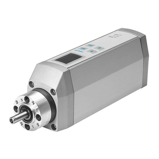
Motor unit
Hide thumbs
Also See for MTR-DCI series:
- Description (352 pages) ,
- Brief overview (74 pages) ,
- Brief overview (74 pages)

Subscribe to Our Youtube Channel
Related Manuals for Festo MTR-DCI series


Summary of Contents for Festo MTR-DCI series
- Page 1 Motor unit MTR−DCI Manual Type MTR−DCI−... Type MTR−DCI−...IO Manual 539 616 en 0411NH [677 795]...
- Page 2 ® ® Adobe and Reader are either a registered trademark or a trademark of Adobe Systems Incorporated in the United States and/or other countries.
- Page 3 ....... . . 539 616 E (Festo AG & Co. KG, D 73726 Esslingen, Federal Republic of Germany, 2004) Internet: http://www.festo.com E−Mail:...
- Page 4 Contents and general instructions Festo P.BE−MTR−DCI−EN en 0411NH...
-
Page 5: Table Of Contents
......1−16 1.3.2 Festo Configuration Tool (FCT) ......1−16 Fitting . - Page 6 ........5−32 5.7.3 Fault messages on the display (MTR−DCI−...H2) ....5−34 Festo P.BE−MTR−DCI−EN en 0411NH...
- Page 7 ............C−1 Festo P.BE−MTR−DCI−EN en 0411NH...
- Page 8 Contents and general instructions Festo P.BE−MTR−DCI−EN en 0411NH...
-
Page 9: Designated Use
(positioning control and position regulator). The mechanical layout and plug−in interface of the MTR−DCI have been optimized for use with electric linear drives (e.g. type DMES...) from Festo. The motor unit can also be used for customer−specific positioniing applications with slow spindle drives. -
Page 10: Safety Instructions
Warning Faults in parametrizing can cause injury to people and damage to property. Enable the controller only if the axis system is correctly installed and parametrized. VIII Festo P.BE−MTR−DCI−EN en 0411NH... -
Page 11: Target Group
Service Please consult your local Festo repair service at the following e−mail address if you have any technical problems. service_international@festo.com Scope of delivery The following items are supplied with motor unit type MTR−... -
Page 12: Important User Instructions
... This means that failure to observe this instruction may result in damage to property. The following pictogram marks passages in the text which describe activities with electrostatically sensitive compo nents. Electrostatically sensitive components: These may be dam aged if they are not handled correctly. Festo P.BE−MTR−DCI−EN en 0411NH... - Page 13 Pictograms Information: Recommendations, tips and references to other sources of information. Accessories: Information on necessary or useful accessories for the Festo product. Environment: Information on the environment−friendly use of Festo prod ucts. Text markings The bullet indicates activities which may be carried out in ·...
-
Page 14: Product−Specific Terms And Abbreviations
Festo Configuration Tool, software with uniform project and data man agement for all supported device types. The special wishes of a device type are supported by PlugIns with the necessary descriptions and dialogues. - Page 15 Min. limit position in negative direction (towards motor). Value must not sink below this level during positioning. Teach mode Operating mode for setting positions by moving to the target position (Teach mode) e.g. when creating position sets. XIII Festo P.BE−MTR−DCI−EN en 0411NH...
- Page 16 Positioning command defined in the position set table, consistin of target position, positioning mode and positioning speed. Maximum 15 position sets are possible on the MTR−DCI with I/O control. Table. 0/1: Index of terms and abbreviations Festo P.BE−MTR−DCI−EN en 0411NH...
-
Page 17: Manuals On Motor Unit Type Mtr−Dci
MTR−DCI−..It also contains information on the functions of the I/O interface for type MTR−DCI−..IO as well as on commissioning with the Festo Configuration tool" (FCT) software package. Product variants are available for coupling to field bus sys tems. -
Page 18: Information On The Version
MTR−DCI under "Device data" Firmware version on the control panel under [Diagnostic] [Software information] Firmware What is new? Which FCT PlugIn? version V−DME1.19 supports linear drives type DMES−25, DMES−40 MTR−DCI V01.00.00 Festo P.BE−MTR−DCI−EN en 0411NH... -
Page 19: Summary Of Components
Summary of components Chapter 1 1−1 Festo P.BE−MTR−DCI−EN en 0411NH... - Page 20 ......1−16 1.3.2 Festo Configuration Tool (FCT) ......1−16 1−2...
-
Page 21: Positioning With Intelligent Drives
(MTR−DCI−...IO) or with the appropriate product variants via the field bus (in preparation: DeviceNet, CANopen, PROFIBUS−DP). Festo offers accessories to suit positioning systems. These accessories match the drive packages and linear drives (see Festo delivery program or catalogue). - Page 22 1. Summary of components Components Higher−order controller e.g. Festo type FEC... Software level: Festo Configuration Tool Motor/controller level: MTR−DCI + coupling Drive level e.g. linear drive type DMES−... Fig. 1/1: Principle of an electric axis with the MTR−DCI−... 1−4 Festo P.BE−MTR−DCI−EN en 0411NH...
- Page 23 (see table Table 1/1) and if applicable further compo nents for the drive, e.g. a mechanical guide, coupling, coupl ing housing etc. Motor unit Drive MTR−DCI−32−... DMES−18 MTR−DCI−42−... DMES−25 MTR−DCI−52−... DMES−40 MTR−DCI−62−... DMES−63 available in preparation Table 1/1: Axis variants with the DMES−... 1−5 Festo P.BE−MTR−DCI−EN en 0411NH...
- Page 24 Speed Type MTR−DCI...G7, gear reduction 6.75:1 0.59 Nm 444 ±10% [1/min] 1.62 Nm 444 ±10% [1/min] Type MTR−DCI...G14, gear reduction 13.73:1 1.13 Nm 218 ±10% [1/min] 3.08 Nm 218 ±10% [1/min] Table 1/2: Gear reduction 1−6 Festo P.BE−MTR−DCI−EN en 0411NH...
-
Page 25: Operating Modes
Temperature monitoring (measuring the motor tempera ture and the power end stage temperature) Voltage monitoring Recognizing faults in the internal voltage supply. Recognizing overvoltages in the intermediate circuit (only type MTR−DCI−62...) Drag fault monitoring Software end position recognition 1−7 Festo P.BE−MTR−DCI−EN en 0411NH... -
Page 26: Method Of Operation
Fig. 1/2: Simplified technical representation of the cascade regulator function The motor unit takes over the following tasks: specification of the nominal positions by positioning con trol comparison of the nominal and actual positions and posi tion control 1−8 Festo P.BE−MTR−DCI−EN en 0411NH... - Page 27 User−specific settings will then be lost. Use CI commands only if you already have experience of · Service Data Objects. If necessary consult the Festo Service. · The FLASH technology enables a firmware update (e.g. for customer−specific firmware) to be loaded into the controller via the RS 232 interface also at a later stage.
-
Page 28: Reference Coordinates And Working Area
The axis zero point is the basis point for the project zero point. The project zero point is specified for the MTR−DCI and is identical to the axis zero point (project zero point offset = 0). 1−10 Festo P.BE−MTR−DCI−EN en 0411NH... - Page 29 Rated stroke: Rated stroke of the drive used, see Technical Specifications for the drive (with DMES−... the stroke specified in the order). Vector representation for the referencing method: Fixed stop, negative Vector representation for the referencing method: Reference switch, negative Table 1/3: Measuring reference system of the electric axis 1−11 Festo P.BE−MTR−DCI−EN en 0411NH...
- Page 30 1) Presetting for selecting the axis type on the control panel 2) Setting only with FCT when a project is started or via [Projekt] [Properties]. 3) Setting only with the control panel [Settings] [Axis type] [Rotation axis] 1−12 Festo P.BE−MTR−DCI−EN en 0411NH...
- Page 31 All the parameters in the controller are always saved in in crements (inch, inch/s, inch/s and are not converted until they are written or read. Measurements transmitted directly via the RS232 refer to an increment basis (conversion see appendix B.3) 1−13 Festo P.BE−MTR−DCI−EN en 0411NH...
-
Page 32: Emergency Stop Concept
By the arrangement of the limit switches and, if necess · ary, by additional appropriate mechanical stops, make sure that the axis always lies within the permitted posi tioning range. 1−14 Festo P.BE−MTR−DCI−EN en 0411NH... -
Page 33: Possibilities Of Commissioning
Commissioning Homing Moving in individual steps − Starting and stopping positioning procedures dur ing commissioning Extended test functions e.g. status dislpays − Testing or demonstrating the position sets Diagnosis/Service Reading and displaying diagnostic data 1−15 Festo P.BE−MTR−DCI−EN en 0411NH... -
Page 34: Control Panel (Mtr−Dci
4, a description of commission ing with the control panel as from chapter 5.2.2. 1.3.2 Festo Configuration Tool (FCT) The Festo Configuration Tool (or brief FCT) is the software platform for configuring and commissioning different compo nents or devices from Festo. - Page 35 An overview of commissioning with the FCT can be found in chapter 5.2.1. The help for the FCT contains the complete information on operating the Festo Configuration Tool. The device−specific PlugIns each have their own help files. You can use the complete help or parts thereof irrespective of a PC by printing them.
- Page 36 The help for the PlugIn MTR−DCI contains the complete in formation on operating the PlugIn. You can open the help as follows: Command [Help] [Contents of installed PlugIns] [Festo · (manufacturer name)] [MTR−DCI (PlugIn name)]. Help button in the window range or dialogue of the Plu ·...
- Page 37 Printed version Directory File FCT help ...(FCT installation directory)\Help\ FCT_de.pdf FCT_de.rtf PlugIn help ...(FCT installation directory)\HardwareFamilies\ MTR−DCI_de.pdf (MTR−DCI) Festo\MTR−DCI\V...\Help\ MTR−DCI_de.rtf For using the print version in the Adobe PDF format you will require the Adobe Reader. 1−19 Festo P.BE−MTR−DCI−EN en 0411NH...
- Page 38 1. Summary of components 1−20 Festo P.BE−MTR−DCI−EN en 0411NH...
- Page 39 Fitting Chapter 2 2−1 Festo P.BE−MTR−DCI−EN en 0411NH...
-
Page 40: Fitting
..........2−5 2−2 Festo P.BE−MTR−DCI−EN en 0411NH... -
Page 41: General Instructions
Screw connections must be fitted free of offset and mechanical tension. Screws must be fitted accurately (otherwise threads will be damaged). The specified torques must be observed. The modules must not be offset. Contact surfaces must be clean (avoid contact faults). 2−3 Festo P.BE−MTR−DCI−EN en 0411NH... -
Page 42: Dimensions Of The Motor Unit
H1 ... 26,5 ±0,15 ±0,2 54,5 76,5 ±0,4 H3 ... 42,3 60,7 Length L [mm] ±1 33,3 46,3 ±1 ±1 L4 ... ±0,2 ±0,2 ±0,3 ±0,3 Width B [mm] 44,8 63,8 ±0.4 53,3 69,5 ±0.4 2−4 Festo P.BE−MTR−DCI−EN en 0411NH... -
Page 43: Fitting Electric Axes
· size for operation with a work load the work load does not collide with the motor or the gear · of the axis when the axis moves into the end position. 2−5 Festo P.BE−MTR−DCI−EN en 0411NH... - Page 44 F shaft loading axial F Torque Mx [Nm] 0,59 1,13 1,62 3,08 * The reference point for forces and torques is the centre of the shaft. Table 2/1: Maximum shaft loading and (gear drive) torques 2−6 Festo P.BE−MTR−DCI−EN en 0411NH...
- Page 45 D1 or D3 (see fig. 2/1), in order to minimize the shaft offset. Fasten the drive to the motor housing with the 4 fastening · screws and tighten the screws with the specified torque (see Table 2/2). 2−7 Festo P.BE−MTR−DCI−EN en 0411NH...
- Page 46 (shaft @ 6 mm) (shaft @ 12mm) Clamping hub 2 Clamping hub 2 (shaft @ 8 mm) (shaft @ 12 mm) Coupling housing with Type Type DME−KG−40−... DME−KG−25−... clamping element 4 fastening screws Table 2/3: Fitting accessories 2−8 Festo P.BE−MTR−DCI−EN en 0411NH...
- Page 47 Clamping hub 1 of the coupling Clamping hub 2 Drive shaft Hub inner surface Ring gear Gap x [mm] MTR−DCI−42 14,4 MTR−DCI−52 15,5 Gap y [mm] DMES−25−... DMES−40−... 16,5 Fig. 2/2: Fitting the coupling type KSE−... 2−9 Festo P.BE−MTR−DCI−EN en 0411NH...
- Page 48 4. Tighten the screw of the clamping element with the torque specified (see Table 2/4). Tightening torque MTR−DCI−42 MTR−DCI−52 Clamping screws of the hubs 4 Nm 8 Nm Fastening screws of the coupling housing 2.9 Nm 5.9 Nm 2−10 Festo P.BE−MTR−DCI−EN en 0411NH...
- Page 49 2. Fitting Tightening torque MTR−DCI−42 MTR−DCI−52 Screw of the clamping element 1.2 Nm 9.9 Nm Table 2/4: Fitting the coupling and the coupling housing 2−11 Festo P.BE−MTR−DCI−EN en 0411NH...
- Page 50 2. Fitting 2−12 Festo P.BE−MTR−DCI−EN en 0411NH...
- Page 51 Installation Chapter 3 3−1 Festo P.BE−MTR−DCI−EN en 0411NH...
-
Page 52: Installation
Connecting the higher−order controller ......3−12 3−2 Festo P.BE−MTR−DCI−EN en 0411NH... -
Page 53: Overview Of Installation
Please note Lay all moveable motor and sensor cables free of bends · and free of mechanical stress, if necessary, in a drag chain. Observe the maximum specified cable lengths. · 3−3 Festo P.BE−MTR−DCI−EN en 0411NH... - Page 54 Interface for connecting with type MTR− any PLC controller DCI−IO..: Plug Reference M8, 3−pin Sensor input for reference switch Socket switch Serial inter M8, 4−pin RS232 interface for face Socket parametrizing, commis sioning and diagnosing 3−4 Festo P.BE−MTR−DCI−EN en 0411NH...
- Page 55 Place protective caps on unused connections in order to prevent such discharges. The plug connectors of the following Festo cables have been designed so that, when inserted and screwed tight, or if fitted with protective covers, the connections on the MTR−DCI will comply with protection class IP54.
-
Page 56: Power Supply
(e.g. EMC). The internal power and controller electronics are supplied with DC voltage via the power supply connection. Plug Description +24 V DC Table 3/2: "Power supply" connection on the MTR− DCI−42/52 3−6 Festo P.BE−MTR−DCI−EN en 0411NH... - Page 57 Connecting cable KPWR−MC−1... Cable length max. 10 m. Use a closed−loop power unit with: · 24 VDC / 6 A for MTR−DCI− 42−... 24 VDC / 10 A for MTR−DCI− 52−... 3−7 Festo P.BE−MTR−DCI−EN en 0411NH...
-
Page 58: Serial Interface
The input (pin 4) is intended exclusively for authorized Festo service personnel. Do not, therefore, apply voltage to pin 4. · Use only the programming cable from Festo. · If necessary, remove the protective cap from the serial · interface of the MTR−DCI. - Page 59 Use this connection only for commissioning. · Do not exceed the maximum permitted signal cable · length of 2.5 m. Disconnect the diagnostic cable during continuous oper · ation. Seal the connection with the protective cap supplied · (type ISK−M8). 3−9 Festo P.BE−MTR−DCI−EN en 0411NH...
-
Page 60: Input For External Reference Switch
When selecting the sensor, note that the accuracy of the · switchover point of the sensor determines the accuracy of the reference point. Use e.g. the following proximity switches from Festo: electric proximity switch SME−8 /SMT−8 (can be fitted in the sensor groove of the drive profile). Switching accuracy: SME−8: 0.2 mm (±0.1 mm) - Page 61 "Technical specifications." M8 socket Description + 24 V DC + 24 V DC voltage output for reference switch Contact reference switch Ground Table 3/4: "Reference switch" connection on the MTR−DCI 3−11 Festo P.BE−MTR−DCI−EN en 0411NH...
-
Page 62: Connecting The Higher−Order Controller
MTR− DCI−... (in preparation). In the case of control via digital I/Os (type MTR−DCI−IO...) note the instructions on connecting and on the function of the I/O interface in chapter 6. 3−12 Festo P.BE−MTR−DCI−EN en 0411NH... -
Page 63: Control Panel (Mtr−Dci−...−H2−Io)
Control panel (MTR−DCI−...−H2−IO) Chapter 4 4−1 Festo P.BE−MTR−DCI−EN en 0411NH... - Page 64 ........4−17 4−2 Festo P.BE−MTR−DCI−EN en 0411NH...
- Page 65 Make sure that the FCT, the control panel and the control · interface of the MTR−DCI are not used at the same time. Please note If necessary, remove the protective foil from the display before commissioning. 4−3 Festo P.BE−MTR−DCI−EN en 0411NH...
-
Page 66: Composition And Function Of The Control Panel
90° steps, see menu command [LCD adjust ment]. The visual display of the operating states is shown via 3 LEDs (see also chapter 5.7.2). Power: Display of the readiness to operate I/F: Positioning status Error: Faults 4−4 Festo P.BE−MTR−DCI−EN en 0411NH... - Page 67 <Menu> re turn to the higher−order menu level. <− −> scrolls within a menu level in order to select a menu command. EDIT sets the parameter Table 4/1: Button function (overview) 4−5 Festo P.BE−MTR−DCI−EN en 0411NH...
-
Page 68: The Menu System
When the power supply is switched on, the MTR−DCI auto = 0.00 mm matically carries out an internal check. At first the display shows the Festo Logo then changes to the status display. The HMI:off status display shows the following information: <Menu>... - Page 69 Selection of the drive, parametrizing, programming the position sets ... (see chapter 4.2.4) } Axis type } Type DMES−... Festo linear axis with servo drive type DMES−.. } Rotation drive Rotation axis with stop } User config Any linear drive...
-
Page 70: Diagnostic" Menu
[Pos. set .table] Menu command for displaying the following entries in the position set table: [Position set ta Description ble] Number of the position set (0..14) absolute (a) or relative (r) positioning Target position Positioning speed 4−8 Festo P.BE−MTR−DCI−EN en 0411NH... - Page 71 Current current Temp [°C] Operating temperature Cycle Number of positioning cycles In−signal hexadecimal representation of the inputs Bit 0: E0 Bit 1: E1 Bit 2: E2 Bit 3: E3 Bit 4: START Bit 5: ENABLE 4−9 Festo P.BE−MTR−DCI−EN en 0411NH...
-
Page 72: Device Control "Hmi Control"
The control interface of the MTR−DCI is deactivated and the control enable is set. The actual status of the ENABLE input then has no effect. The device control is carried out via the control interface of the MTR−DCI. Human Machine Interface 4−10 Festo P.BE−MTR−DCI−EN en 0411NH... -
Page 73: Settings" Menu
Design of axis driven by the MTR−DCI. [Axis type] Parameters [Type DMES−...] Festo linear axis with servo drive type DMES−... The selection defines the following settings: the feed constant e.g. MTR−DCI 42 + DMES−25: 2.5 mm / spindle revolution MTR−DCI 42 + DMES−40: 4 mm / spindle revolution... - Page 74 EEPROM with the menu command [Save...]: Save the parameter settings with the menu command · [Save]. Only then will the settings be retained even if the power supply is switched off or if there is a power fail ure. 4−12 Festo P.BE−MTR−DCI−EN en 0411NH...
- Page 75 EEPROM with the menu command [Save...]: Save the parameter settings with the menu command · [Save]. Only then will the settings be retained even if the power supply is switched off or if there is a power fail ure. 4−13 Festo P.BE−MTR−DCI−EN en 0411NH...
- Page 76 EEPROM with the menu command [Save...]: Save the parameter settings with [Save]. Only then will · the settings be retained even if the power supply is switched off or if there is a power failure. 4−14 Festo P.BE−MTR−DCI−EN en 0411NH...
- Page 77 2. Confirm your entry with <Enter>. The next entry position will be displayed. 3. Repeat the entry for the further entry positions. When the third figure has been entered, access via the con trol panel is enabled. 4−15 Festo P.BE−MTR−DCI−EN en 0411NH...
- Page 78 If the active password in the MTR−DCI should be lost in spite of care being taken: you can delete it by entering a master password. In this case please contact your Festo Service partner. 4−16 Festo P.BE−MTR−DCI−EN en 0411NH...
-
Page 79: Positioning" Menu
Please note Please note that position sets with speed v = 0 or invalid target positions ( −> Fault "TARGET POSITION OUT OF LIMIT) cannot be processed. 4−17 Festo P.BE−MTR−DCI−EN en 0411NH... - Page 80 EMERG.STOP<Menu> Function EMERG With<Menu> you can interrupt the positioning .STOP procedure (> Error mode EMERG.STOP; con Menu firm with <Enter>, then automatic return to the status display). 4−18 Festo P.BE−MTR−DCI−EN en 0411NH...
- Page 81 During position travel the following information is displayed: Pos 1 = 100.00 mm the active position set Pos... v = 20 mm/s = 90.00 mm the target position x EMERG.STOP<Menu> the speed v the current position xa. 4−19 Festo P.BE−MTR−DCI−EN en 0411NH...
- Page 82 With <Enter> you can interrupt the positioning Enter STOP travel "Position set table" [Demo pos tab]. The current positioning set will be processed before the axis stops. A new start will be made with position set 0. 4−20 Festo P.BE−MTR−DCI−EN en 0411NH...
-
Page 83: Commissioning
Commissioning Chapter 5 5−1 Festo P.BE−MTR−DCI−EN en 0411NH... - Page 84 ........5−32 5.7.3 Fault messages on the display (MTR−DCI−...H2) ....5−34 5−2 Festo P.BE−MTR−DCI−EN en 0411NH...
-
Page 85: Commissioning
Please observe the notes in the operating instructions for · the servo drive. 5−3 Festo P.BE−MTR−DCI−EN en 0411NH... -
Page 86: Installing And Starting The Fct
You can install the FCT from the CD ROM as follows: 1. Close all programs. 2. Place the CD Festo Configuration Tool in your CD ROM drive. If Auto Run is activated on your system, the installa tion will start automatically and you can omit steps 3 and 3. -
Page 87: Procedure For Commissioning
FCT is activated. Control by the FCT must not be activated while the drive · is in motion or when control is being carried out via I/Os. 5−5 Festo P.BE−MTR−DCI−EN en 0411NH... - Page 88 FCT/PlugIn help. Explanations of reference coordinates and the working area can be found in chapter 1.1.2. In order to complete commissioning note the instructions · for operation in the FCT/PlugIn help and in chapter 5.6 5−6 Festo P.BE−MTR−DCI−EN en 0411NH...
- Page 89 CI command 20F1 (Data memory control) (see chapter 7). User−specific settings will then be lost. Use CI commands only if you already have experience of · Service Data Objects. If necessary consult the Festo Service. · 5−7 Festo P.BE−MTR−DCI−EN en 0411NH...
-
Page 90: Commissioning With Fct
1. Connect the MTR−DCI to your PC via the RS232 interface. Note here the instructions in chapter 3.3. 2. Starting the FCT Double−click on the Festo Configuration Tool Icon on the desktop. switch to Windows and select the entry [Festo Software] [Festo Configuration Tool] in the menu [Start]. - Page 91 Further information can be found in the PlugIn help: Com mand [Help] [Contents of installed PlugIns] [Festo (manufac turer name)] [MTR−DCI (PlugIn name)] e.g.: for describing the dialogues of the "Device MTR−DCI"...
-
Page 92: Commissioning With Control Panel (Mtr−Dci
3. Carry out homing. 5.3.3 4. Teach the following axis parameters for defining the axis 5.3.4 zero point and the working area: Offset of the axis zero point to the reference point Positive and negative software end positions 5−10 Festo P.BE−MTR−DCI−EN en 0411NH... - Page 93 7. If necessary, optimize the settings for position sets as well as for the reference coordinates and the working area. 8. Check the function of the contol interface of the MTR−DCI (function test). 9. In order to complete commissioning note the instructions on operation. 5−11 Festo P.BE−MTR−DCI−EN en 0411NH...
-
Page 94: Parametrizing And Referencing (Mtr−Dci
1. Select the servo drive which matches your positioning Axis type system. Type DMES... Rotation drive Festo servo drive [type DMES−...] User config Rotation axis [Rotation drive] Any linear drive [User config] 2. If necessary, use the arrow buttons to set axis−specific parameters, depending on the entry request (see also chapter 4.2.4). - Page 95 Maximum impact pulse = mass x speed Please refer to the manual for your servo drive for the per mitted value. 5−13 Festo P.BE−MTR−DCI−EN en 0411NH...
- Page 96 Set the offset of the axis zero point · Limit the positioning range by defining valid softwere · end positions during commissioning (see chapter 1.1.2). Specify target positions only within the permitted posi · tioning range. 5−14 Festo P.BE−MTR−DCI−EN en 0411NH...
- Page 97 1 Axis moves at search speed v to the reference switch, and it reverses to ascertain the reference point. 2 Then axis moves at speed v from the reference point to the axis zero point. 5−15 Festo P.BE−MTR−DCI−EN en 0411NH...
- Page 98 [Save]. Only then will the settings be retained even if the power supply is switched off or if there is a power failure. Finally, carry out homing, otherwise the previous refer · ence system of the MTR−DCI will remain unmodified. 5−16 Festo P.BE−MTR−DCI−EN en 0411NH...
-
Page 99: Carrying Out Homing
The drive then moves at speed v_s0 to the axis zero point. (Fig. 5/1 2 ) Travel to the reference point Travel to the axis zero point AZ Fig. 5/1: Homing (example: Fixed stop, negative) 5−17 Festo P.BE−MTR−DCI−EN en 0411NH... - Page 100 · chapter 5.4.1). Move the drive to the desired position manually with · the arrow buttons. Interrupt the procedure with ESC<menu>, in order that · the position is not included in the position set table. 5−18 Festo P.BE−MTR−DCI−EN en 0411NH...
- Page 101 Check the settings of the parameters. · Position the drive in the Teach mode so that at the start in · the search direction it standsin front of the stop or refer ence switch. Repeat homing. · 5−19 Festo P.BE−MTR−DCI−EN en 0411NH...
-
Page 102: Teach The Axis Zero Point And The Software End Positions
Note that these values refer to the previous axis zero point. Teach the software end positions and the target posi · tions again. Teach the negative software end position and the positive software end position: 5−20 Festo P.BE−MTR−DCI−EN en 0411NH... - Page 103 4. Save the parameter settings with [Save]. Only then will the settings be retained even if the power supply is switched off or if there is a power failure. 5−21 Festo P.BE−MTR−DCI−EN en 0411NH...
-
Page 104: Positioning With Position Sets (Mtr−Dci
During the teach procedure the motor turns or the con nected axis starts to move. Make sure that nobody can place his/her hand in the · positioning range of the moveable mass and that no objects lie in its path. 5−22 Festo P.BE−MTR−DCI−EN en 0411NH... -
Page 105: Teach The Position Sets
Move the drive to the desired target position manually · with the arrow buttons. Accept the position reached with OK<Enter>. The set · ting of the target position and the positioning mode will then become effective in the drive. 5−23 Festo P.BE−MTR−DCI−EN en 0411NH... - Page 106 5. Save the position set with [Save]. Only then will the set tings be retained even if the power supply is switched off or if there is a power failure. 6. Enter the next position set. 5−24 Festo P.BE−MTR−DCI−EN en 0411NH...
-
Page 107: Test Run
Check the displayed coordinates of the axis. · With EMERG.STOP <Menu> you can interrupt the current positioning procedure. 5. If necessary, optimize the settings for position sets as well as for the reference coordinates and the working area. 5−25 Festo P.BE−MTR−DCI−EN en 0411NH... - Page 108 Program or start homing as well as some positioning · movements. Check the positioning behaviour. · 5−26 Festo P.BE−MTR−DCI−EN en 0411NH...
-
Page 109: Instructifunctions Function Operatifunction
With self−locking axes the relation of the current axis position to the axis zero point is retained (quasi absolute positioning). New homing is not then required. 5−27 Festo P.BE−MTR−DCI−EN en 0411NH... - Page 110 5−28 Festo P.BE−MTR−DCI−EN en 0411NH...
- Page 111 Caution Damage to components Movement to the mechanical end positions is not per mitted during operation. If movement is made to the end positions with a heavy load, the end positions may become blocked. 5−29 Festo P.BE−MTR−DCI−EN en 0411NH...
-
Page 112: Care And Maintenance
EMERGENCY STOP concept correspon dingly in the control programs. Care and maintenance The motor units do not require maintenance during their specified service life. Follow the maintenance instructions for the components used. 5−30 Festo P.BE−MTR−DCI−EN en 0411NH... -
Page 113: Diagnosis And Fault Display
FCT (with active device connection): Display of the current position set, target and actual positions as well as speed. Display the operating mode, special outputs and op erating states as swell as fault messages of the con nected MTR−DCI. 5−31 Festo P.BE−MTR−DCI−EN en 0411NH... -
Page 114: Led Status Displays
Operating voltage LED (POWER) Interface LED e.g. positioning status, controller enable (I/F) Fault LED (ERROR) Operating voltage POWER Status Operating voltage applied green Operating voltage not applied, if necessary check oper ating voltage connection. ating voltage connection. 5−32 Festo P.BE−MTR−DCI−EN en 0411NH... - Page 115 LED ERROR = out Fault display ERROR Status Internal fault. The MTR−DCI is not ready to operate (deactivated). No internal fault registered. The MTR−DCI is ready to operate. The MTR−DCI is ready to operate. 5−33 Festo P.BE−MTR−DCI−EN en 0411NH...
-
Page 116: Fault Messages On The Display (Mtr−Dci
If there is a fault, the drive will be stopped. Eliminate the cause of the fault. · Quit the fault message · on the control panel with <Enter> via I/O by removing the ENABLE signal (falling edge). 5−34 Festo P.BE−MTR−DCI−EN en 0411NH... - Page 117 5. Commissioning Faults Possible cause HARDWARE ERROR Device fault e.g. EEPROM defective. In this case please contact your Festo Service. · HOMING Faults during homing ERROR Possible causes: Homing interrupted Reference switch defective If necessary, check the function of the reference switch.
- Page 118 Check the voltage supply. · Power unit too weak? Supply line too long? TARGET POSITION OUT The specified target position is outside the permitted positioning range. OF LIMIT Check the software end positions and the target position. · 5−36 Festo P.BE−MTR−DCI−EN en 0411NH...
- Page 119 Communication with the higher−order controller Chapter 6 6−1 Festo P.BE−MTR−DCI−EN en 0411NH...
- Page 120 ..........6−11 6−2 Festo P.BE−MTR−DCI−EN en 0411NH...
-
Page 121: Communication With The Higher−Order Controller
LAST ACTUAL POSITION NOT SAVED with a non self−locking axis each time it is switched on. Use control cable KES−MC−1−SUB−9 for connecting the MTR− DCI to a higher−order controller (PLC). 6−3 Festo P.BE−MTR−DCI−EN en 0411NH... - Page 122 If a voltage is applied and the output pins are used incor rectly, the device may be seriously damaged, therefore do not connect voltage to the outputs. · Note the current limit at the outputs. · 6−4 Festo P.BE−MTR−DCI−EN en 0411NH...
-
Page 123: Description Of The I/Os
HIGH HIGH HIGH HIGH HIGH HIGH HIGH HIGH HIGH HIGH HIGH HIGH HIGH HIGH HIGH HIGH HIGH HIGH HIGH 15 * HIGH HIGH HIGH HIGH * Homing Table 6/2: Binary code of the position set 6−5 Festo P.BE−MTR−DCI−EN en 0411NH... - Page 124 If there is a 1−signal at the ENABLE input, the controller of the axis will be switched on. The current position set will be pro cessed at the next START signal. 6−6 Festo P.BE−MTR−DCI−EN en 0411NH...
- Page 125 1−signal at this output indicates that a positioning task is completed and that the START input has been reset. Level MOTION COMPLETE Positioning procedure is being carried out or the START signal is still at HIGH. HIGH Positioning task is completed 6−7 Festo P.BE−MTR−DCI−EN en 0411NH...
-
Page 126: Function Description (Pulse−Time Diagram)
START signal is still at HIGH, the MC signal will remain at LOW until the START signal is reset. This coupl ing of START / MC signal enables signal confirmation for the PLC (handshake function). 6−8 Festo P.BE−MTR−DCI−EN en 0411NH... - Page 127 READY and the MC signals will be reset to LOW level. Any starting signal will then be ignored. When the ENABLE signal is set (> HIGH), the outputs will be set again according to their status. 6−9 Festo P.BE−MTR−DCI−EN en 0411NH...
- Page 128 Error 2 If there is a fault during operation, the outputs READY and MOTION COMPLETE will be reset (LOW). The fault must be quitted as described for Error1. 6−10 Festo P.BE−MTR−DCI−EN en 0411NH...
-
Page 129: I/O Specification
Electrical isolation Optocoupler Outputs Number of digital Logical out puts Maximum current Imax = 200 mA Imax = 60 mA Rated current Irated = 100 mA Irated = 50 mA Overload protection Forward resistance 1 6−11 Festo P.BE−MTR−DCI−EN en 0411NH... - Page 130 6. Communication with the higher−order controller 6−12 Festo P.BE−MTR−DCI−EN en 0411NH...
-
Page 131: Communication Via The Serial Interface
Communication via the serial interface Chapter 7 7−1 Festo P.BE−MTR−DCI−EN en 0411NH... - Page 132 ........7−11 7−2 Festo P.BE−MTR−DCI−EN en 0411NH...
-
Page 133: Communication Via The Serial Interface
(1, 2 or 4 data bytes) depends on the data type of the Object to be read or written. As from version 1.19, the firmware of the MTR−DCI offers the possibility of simulating SDO access with CI commands via the RS232 interface. 7−3 Festo P.BE−MTR−DCI−EN en 0411NH... -
Page 134: Procedure For Data Transfer
Inform yourself about using the Objects in the CiA Draft · Standard 402 before you use the CI commands of the Command Interpreter of the MTR−DCI. For data transfer you will require a commercially−available terminal program. 7−4 Festo P.BE−MTR−DCI−EN en 0411NH... - Page 135 Use the CI commands only if you already know their ef · fects and if they are permitted for your MTR−DCI. Transfer the commands with a terminal program. · For the syntax of the commands see appendix B.1. 7−5 Festo P.BE−MTR−DCI−EN en 0411NH...
- Page 136 Please note Transmission of the command is repeated 8 times by the host. After that the serial connection is regarded as unus able and is interrupted. Transmission must then be initial ized again. 7−6 Festo P.BE−MTR−DCI−EN en 0411NH...
-
Page 137: Object Directory
Note the detailed description on using the Objects in · appendix B.2 (sorted according to index number). Please contact Festo if you require a firmware update. · The Objects listed are implemented in the controller of the MTR−DCI as from firmware version V−DME1.19. -
Page 138: General Objects
607E Gear Ratio Defining or reading the gear reduction (motor revol 6091 utions / power take−off revolution) 6092 Feed Constant Defining or reading the feed constants (positioning path / power take−off path e.g. spindle pitch) 7−8 Festo P.BE−MTR−DCI−EN en 0411NH... -
Page 139: Objects For Creating Position Sets
Position table element Object for managing the position set table 20E0 607A Target position Defining or reading a target position Profile velocity Defining or reading the speed for a positioning pro 6081 cedure 7−9 Festo P.BE−MTR−DCI−EN en 0411NH... -
Page 140: Objects For Controlling
7. Communication via the serial interface 7.3.5 Objects for controlling Caution The control parameters of the MTR−DCI are preset. Modifi cation is only permitted for service cases. If necessary con sult the Festo Service. Name Explanation Index Position Demand Value... -
Page 141: Objects For Diagnosis
Transmission fault between host (PC) and target device 2FF0 Device Error Read or delete a device fault 2FF1 2FFF Cycle number Display cycles traversed, for diagnostic purposes Status Word Display status (fault, motion complete ..) 6041 7−11 Festo P.BE−MTR−DCI−EN en 0411NH... - Page 142 7. Communication via the serial interface 7−12 Festo P.BE−MTR−DCI−EN en 0411NH...
- Page 143 Technical appendix Appendix A A−1 Festo P.BE−MTR−DCI−EN en 0411NH...
-
Page 144: A. Technical Appendix
........A−7 A−2 Festo P.BE−MTR−DCI−EN en 0411NH... -
Page 145: A.1 Technical Specifications
PELV power unit (Protected Extra Low Volt (protection against direct and indirect contact age) as per EN 60204−1/IEC 204) The device is intended for industrial uage. The maximum permitted I/O signal cable length is 30 m. A−3 Festo P.BE−MTR−DCI−EN en 0411NH... - Page 146 Mass moment of inertia (gear) [kg cm 0,00235 0,00441 0,01132 0,01711 Shaft loading radial Shaft loading axial Flange diameter [mm] Product weight [kg] 1,715 1,824 3,104 3,285 Gear ratio 6.75:1; 1−stage Gear ratio 13.73:1; 2−stages A−4 Festo P.BE−MTR−DCI−EN en 0411NH...
- Page 147 A. Technical appendix Electrical data MTR−DCI−42 MTR−DCI−52 Rated voltage [V DC] 24 ±10% 24 ±10% Rated current (motor) 2 ± 20% 5,1 ± 20% Peak current Rated output (motor) A−5 Festo P.BE−MTR−DCI−EN en 0411NH...
-
Page 148: A.2 Accessories
A. Technical appendix Accessories Cable 2.5m Control cable KES−MC−1−SUB−9−2,5 KES−MC−1−SUB−9−5 KES−MC−1−SUB−9−10 Programming KPWR−MC−M8−SUB−9−2,5 cable Supply cable KDI−MC−1−SUB−9HC−2,5 KDI−MC−1−SUB−9HC−5 KDI−MC−1−SUB−9HC−10 User documentation in paper form German P.BE−MTR−DCI−IO−DE English P.BE−MTR−DCI−IO−EN French P.BE−MTR−DCI−IO−FR Italian P.BE−MTR−DCI−IO−IT Spanish P.BE−MTR−DCI−IO−ES Swedish P.BE−MTR−DCI−IO−SV A−6 Festo P.BE−MTR−DCI−EN en 0411NH... -
Page 149: A.3 Motor Characteristic Curves
A. Technical appendix Motor characteristic curves Speed I [A] n [1/min] MTR−DCI−42−...−G7 Current Recommended operating range Overload range M [Nm] I [A] n [1/min] MTR−DCI−42−...−G14 M [Nm] Fig. A/1: Motor characteristic curves MTR−DCI−42−... A−7 Festo P.BE−MTR−DCI−EN en 0411NH... - Page 150 A. Technical appendix Speed n I [A] n [1/min] MTR−DCI−52−...−G7 Current I Recommended operating range Overload range M [Nm] I [A] n [1/min] MTR−DCI−52−...−G14 M [Nm] Fig. A/2: Motor characteristic curves MTR−DCI−52−... A−8 Festo P.BE−MTR−DCI−EN en 0411NH...
- Page 151 Supplementary information Appendix B B−1 Festo P.BE−MTR−DCI−EN en 0411NH...
-
Page 152: B. Supplementary Information
........B−41 B−2 Festo P.BE−MTR−DCI−EN en 0411NH... -
Page 153: B.1 Ci Commands
All commands will be entered as a character sequence with out empty spaces. A hex character corresponds to a Char character in hex format. Command Reply =IIIISS:<value>CR =IIIISS:<value> <PS> <CR> ?IIIISS<CR> =IIIISS:<value> <PS> <CR> W = write, R = read B−3 Festo P.BE−MTR−DCI−EN en 0411NH... - Page 154 8 bits with sign: −128...127 UINT16 16 bits without sign: 0...65535 INT16 16 bits with sign: −32768..0.32767 UINT32 32 bits without sign: 0...(2 −1) INT32 32 bits with sign: −(2 )...(2 −1) V−STRING corresponds to the preset string B−4 Festo P.BE−MTR−DCI−EN en 0411NH...
- Page 155 4 bits; it is known as a tetrad <Tn>. The first tetrad transferred contains the higher−value bits of the value. Gen eral information: Tetrad <Tn> contains the bits b ...b Example: UINT8 Tetrad T Tetrad T B−5 Festo P.BE−MTR−DCI−EN en 0411NH...
- Page 156 The checksum is formed from the sum of all sent bytes and shortened to 1 byte (modulo 256) The other station must compare the sent command with the "echo" of the controller and process the checksum. Checksum Syntax IIIISS:<checksum> Format 2 hexadecimal figures Type UINT8 B−6 Festo P.BE−MTR−DCI−EN en 0411NH...
-
Page 157: B.2 Object Description
B. Supplementary information Object description B−7 Festo P.BE−MTR−DCI−EN en 0411NH... -
Page 158: B.2.1 Object Classification (Overview)
Position Demand Value INT32 6062 Position Actual Value INT32 6064 Position Window Time UINT16 6068 Velocity Demand Value INT32 606B Velocity Actual Value INT32 606C Max Current UINT16 6073 6075 Motor Rated Current UINT32 B−8 Festo P.BE−MTR−DCI−EN en 0411NH... - Page 159 V−string R 6505 dress Drive data Array UINT16 6510 40 41 42 43 R = read only, W = write RW = read/write, IIII = Index (4 hex figures), SS = Subindex ( 2 hex figures) B−9 Festo P.BE−MTR−DCI−EN en 0411NH...
-
Page 160: B.2.2 Group 1Xxx
V−STRING device_name Object 1009 Coding of hardware version Example: "V0204" Name Class IIII Type manufacturer_ 1009 V−STRING hardware_version Object 100A Coding of firmware version Example: "V−DME1.19" Name Class IIII Type manufacturer_ Array 100A V−STRING firmware_version B−10 Festo P.BE−MTR−DCI−EN en 0411NH... -
Page 161: B.2.3 Group 2Xxx
Comment Do not use − reserved for CANopen <0> <1> <2> Position record 0 <3> Position record 1 <4> Position record 3 <5> Position record 4 <16> Position record 15 <17> Homing (position record 16) B−11 Festo P.BE−MTR−DCI−EN en 0411NH... - Page 162 Subindex 02 Number of positions after the decimal point (n) Value Default: Comment <2>...<4> <2> Cannot be set for MTR−DCI−IO (fix n = 2) B−12 Festo P.BE−MTR−DCI−EN en 0411NH...
- Page 163 Name Class IIII Type position_table_ Array 20E0 UINT16 element element INT32 INT32 Subindex 01 Positioning mode Comment <1> Absolute positioning <0> Relative positioning 1... 15 not used * * unused bits have contents = 0 B−13 Festo P.BE−MTR−DCI−EN en 0411NH...
- Page 164 Increments Object 20E2 Setting and reading the axis parameters Axis length Gear factor Name Class IIII Type axis_parameter Array 20E2 INT32 INT32 INT32 Subindex 01 Axis length Value Default Unit −2 ...+(2 −1) <1> Increments B−14 Festo P.BE−MTR−DCI−EN en 0411NH...
- Page 165 The status after deletion corresponds to the standard factory setting. The gear factor returns to the standard factory setting = 6,75. For setting the gear factor (=13,7): Consult your Festo · Service. Always carry out a first commissioning after deleting the ·...
- Page 166 Entering the super password For resetting all passwords (FCT passwors and local password for HMI, Object 20FB) Contact the Festo Service if you require the super password. Object 20FB Managing the (local) HMI password for enabling certain func tions which are carried out via the control panel.
- Page 167 With an unfavourable parameter setting the LCD remains black. Name Class IIII Type LCD_parameter Array 20FF UINT8 UINT8 Subindex 01 LCD voltage Value Default Comment <1>...<5> <5> Subindex 02 LCD contrast Value Default Comment <0>...<63> <0> B−17 Festo P.BE−MTR−DCI−EN en 0411NH...
- Page 168 Please note The host repeats transmission of the command eight ti mes. After that the serial connection is regarded as unus able and is interrupted. The transmission must be reinitial ized (initialization see chapter 7.2) B−18 Festo P.BE−MTR−DCI−EN en 0411NH...
- Page 169 EMERGENCY STOP HOMING ERROR OVERHEATING POWER DOWN t−ERROR HARDWARE ERROR TARGET POSITION OUT OF LIMIT LAST POSITION NOT SAVED Explanations of the fault messages can be found in chapter 5.7.3. Table B/3: Value table: device_error B−19 Festo P.BE−MTR−DCI−EN en 0411NH...
- Page 170 B. Supplementary information Object 2FFF Display cycles traversed (for diagnostic purposes) Name Class IIII Type cycle_number 2FFF UINT32 Value Default Unit 0 ... 2 <0> B−20 Festo P.BE−MTR−DCI−EN en 0411NH...
-
Page 171: B.2.4 Group 6Xxx
VOLTAGE DISABLE end stage OFF 0x000D 0x001F Start ABSOLUTE movement 0x005F Start RELATIVE movement 0x010F 0x0100 Stop movement 0x008F 0x0080 Reset fault + ENABLE OPERATION. Replay without 0x0080 − mask 0x004F 0x0040 Set Target Position as RELATIVE. B−21 Festo P.BE−MTR−DCI−EN en 0411NH... - Page 172 0: MOTION_NO_COMPLET. (mask at bit 10: 0x0400) 0x0800 1: Internal limit active, 0: Internal limit not active. t is active (mask at bit 11: 0x0800) 0x2000 1: HOMING_ERROR, 0: HOMING_NO_ERROR. (mask at bit 13: 0x2000) B−22 Festo P.BE−MTR−DCI−EN en 0411NH...
- Page 173 Profile Position Mode (position controller with positio ning mode) 0x03 reserved 0x04 reserved 0x06 Homing Mode (reference travel) Object 6061 Reading the current operating mode Name Class IIII Type modes_of_ 6061 INT8 operation_display Values see Object 6060. B−23 Festo P.BE−MTR−DCI−EN en 0411NH...
- Page 174 Nominal value of the position controller Name Class IIII Type position_demand_ 6062 INT32 value Value Unit −2 ...(2 −1) Increments Object 6064 Actual value of the position controller Name Class IIII Type position_actual_ 6064 UINT32 value Value Unit 0...2 Increments B−24 Festo P.BE−MTR−DCI−EN en 0411NH...
- Page 175 Class IIII Type Velocity_Demand 606B INT32 _Value Value Unit −2 ...(2 −1) Increments Object 606C Actual value of the speed regulator Name Class IIII Type Velocity_Actual 6068 INT32 _Value Value Unit −2 ...(2 −1) Increments B−25 Festo P.BE−MTR−DCI−EN en 0411NH...
- Page 176 (higher) nominal speeds may not therefore be achieved. Name Class IIII Type max_current 6073 UINT16 Value Default Comment 0 ... + 2000 <1500> Specification in one thousandth of the rated current (see Object 6075) B−26 Festo P.BE−MTR−DCI−EN en 0411NH...
- Page 177 Defining or reading a target position. This will be saved in the column intended in the line addressed by Object <2032>in the position table. No movement is yet made. Name Class IIII Type target_position 607A INT32 Value Unit −2 ...+(2 −1) Increments B−27 Festo P.BE−MTR−DCI−EN en 0411NH...
- Page 178 Subindex 01 Lower limit value (Min−Limit) Value Default Unit −2 ...+(2 −1) <1> Increments Subindex 02 Upper limit value (Max−Limit) Value Default Unit −2 ...+(2 −1) 4 500 000 MTR−DCI−42 Increments 3 375 000 MTR−DCI−52 B−28 Festo P.BE−MTR−DCI−EN en 0411NH...
- Page 179 Defining or reading the final speed for a positioning proce dure. This will be saved in the column intended in the line addressed by Object <2032>in the position table. No move ment is yet made. Name Class IIII Type profile_velocity 6081 INT32 B−29 Festo P.BE−MTR−DCI−EN en 0411NH...
- Page 180 Value Default Unit 4000 a 180 000 48 000 Increments/s Object 608F Reading the encoder resolution = encoder increments / motor revolutions Name Class IIII Type encoder_ Array 608F UINT32 resolution resolution UINT32 B−30 Festo P.BE−MTR−DCI−EN en 0411NH...
- Page 181 6091 UINT32 UINT32 *) Write (W) only in service cases Subindex 01 Motor revolutions (gear ratio counter) Value Default 0 ... 2 Subindex 02 Power take−off revolutions (gear ratio denominator) Value Default 0 ... 2 B−31 Festo P.BE−MTR−DCI−EN en 0411NH...
- Page 182 * cannot be set Subindex 01 Positioning path (feed constant counter) e.g. spindle gradient Value Default Unit ìm 1...2 2500 MTR−DCI−42 4000 MTR−DCI−52 Subindex 02 Power take−off revolution (feed constant denominator) Value (default) Comment cannot be set B−32 Festo P.BE−MTR−DCI−EN en 0411NH...
- Page 183 All values must be divisible by 200 and must be positive, otherwise they will be rounded and negative values has been set to zero. Value Default Unit 1 ... 50000 22400 MTR−DCI−42 Increments/s 16800 MTR−DCI−52 B−33 Festo P.BE−MTR−DCI−EN en 0411NH...
- Page 184 UINT16 reserved reserved UINT16 *) Write only in service cases Caution The control parameters of the MTR−DCI are preset. Modifi cation is only permitted for service cases. If necessary con sult the Festo Service. B−34 Festo P.BE−MTR−DCI−EN en 0411NH...
- Page 185 Subindex 14 I−share of speed regulator Value Default 200 ... 500 MTR−DCI−42, 52 Subindex 15 Amplification of current regulator Value Default 200 ... 800 MTR−DCI−42.52 Subindex 17 Amplification of speed regulator (path generator) Value (default) B−35 Festo P.BE−MTR−DCI−EN en 0411NH...
- Page 186 Do not save current position at power−off in EE PROM Object 60FD Image of the digital inputs in the upper bits. Name Class IIII Type digital_inputs 60FD UINT32 Value Comment 0 ... 2 As from bit 16 (Bit 0 ... 15 are reserved) B−36 Festo P.BE−MTR−DCI−EN en 0411NH...
- Page 187 Classification of the motor. Name Class IIII Type motor_type 6402 UINT16 Value (default) Comment cannot be set Object 6410 Reading the motor data. Name Class IIII Type motor_data Record 6410 UINT32 Subindex 01 Series number B−37 Festo P.BE−MTR−DCI−EN en 0411NH...
- Page 188 Classification of the drive functionality. Name Class IIII Type suppor 6502 UINT32 ted_drive_modes Value (default) Comment 0x21 cannot be set Object 6504 Manufacturer name. Name Class IIII Type drive_ 6504 V−string manufacturer Value (default) Festo AG & Co. KG B−38 Festo P.BE−MTR−DCI−EN en 0411NH...
- Page 189 Record 60FB UINT16 UINT16 UINT32 UINT16 INT16 UINT16 UINT32 Subindex 31 Temperature of the end stage Value Unit −40 ... + 85 °C Subindex 32 Maximum temperature of the end stage Value Unit °C B−39 Festo P.BE−MTR−DCI−EN en 0411NH...
- Page 190 I/O interface OFF <1> I/O interface ON Subindex 0xA0 Series number of the controller Format: 0xTTMYYSSS Value Comment 8 bits: 0x01 ... 0x1F 4 bits: 0x1 ... 0xC Month 8 bits:0x00...0x63 Year 12 bits: 0x001...0xFFF Series number B−40 Festo P.BE−MTR−DCI−EN en 0411NH...
-
Page 191: B.3 Converting The Measuring Units
FCT. The direct tansfer of values via the serial interface with CI commands always takes place in the basis system and it is assumed that conversion into increments has already taken place. B−41 Festo P.BE−MTR−DCI−EN en 0411NH... - Page 192 500 x 4 = 2000 [incr/rev] 500 x 4 = 2000 [incr/rev] depending on drive, here type DMES−..Specification in 2 natural numbers for counter or denominator of the fraction with MTR−DCI: pulse quadruplication by digital interpolation B−42 Festo P.BE−MTR−DCI−EN en 0411NH...
- Page 193 [ m] > [inc] gear feed [ inch] > [inc] gear minch minch minch feed minch gear minch feed 25,4 + UF 25, 4 minch [rev] > [inc] + enc gear [°] > [inc] gear ° ° ° B−43 Festo P.BE−MTR−DCI−EN en 0411NH...
- Page 194 (UF / 360) ** [°/s ] x [inc/rev] / [°/rev] x UF [°/s ] x [inc/s * conversion [ m] > [ inch]: 1ìinch = 25,4 ìm ** conversion [rev] > [°]: 1[rev] = 360° B−44 Festo P.BE−MTR−DCI−EN en 0411NH...
- Page 195 Index Appendix C C−1 Festo P.BE−MTR−DCI−EN en 0411NH...
-
Page 196: C. Index
C. Index C−2 Festo P.BE−MTR−DCI−EN en 0411NH... - Page 197 Controller ......XII , 3−4 , 3−12 C−3 Festo P.BE−MTR−DCI−EN en 0411NH...
- Page 198 ........, 1−9 C−4 Festo P.BE−MTR−DCI−EN en 0411NH...
- Page 199 ........2−4 C−5 Festo P.BE−MTR−DCI−EN en 0411NH...
- Page 200 ......... . 1−9 C−6 Festo P.BE−MTR−DCI−EN en 0411NH...
- Page 201 ......5−20 Software Festo Configuration Tool (FCT) ....1−16 Installing the FCT .
- Page 202 Working stroke ....... . 1−11 C−8 Festo P.BE−MTR−DCI−EN en 0411NH...
- Page 203 In such a save the electronic documentation on status of the product can be found on case, the liability of Festo is limited to the central processors (machines) the type plate of the product. If the the damage recognizable by Festo used at the location.
Need help?
Do you have a question about the MTR-DCI series and is the answer not in the manual?
Questions and answers