
Related Manuals for Curtis G4 Seraphim SERA2B


Summary of Contents for Curtis G4 Seraphim SERA2B
- Page 1 USER GUIDE G4 Seraphim ® Digital Coffee Brewing System READ AND SAVE THESE INSTRUCTIONS NOTICE TO INSTALLER: Please leave this booklet with the machine. 070120D FC18-SERA, FRONT COVER F-10017 revB...
-
Page 2: Table Of Contents
.......................ES25 ....................ES26 .....................ES157 .....................................................................................................................EC1 ..............................Contact Information Wilbur Curtis Co., Inc. 6913 Acco Street | Montebello, CA 90640 US Phone: 323-837-2300 | Toll Free: 800-421-6150 Email: csrassistance@wilburcurtis.com | Web: www.wilburcurtis.com . - 4:00 . PT Email: techsupport@wilburcurtis.com... -
Page 3: Fs18
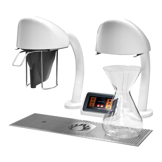
® • Standard Seraphim package includes two Seraphs (brew heads), one Curtis 5.0 gallon hot water tower, G4 touchscreen and a drip tray assembly. • Brewing methods – Chemex, Kalita, V60, Bee Dripper, Able Kone Brewing System, French Press and more. -
Page 4: Is2
INSTRUCTIONS could result in personal injury or void the warranty. • This appliance is designed for commercial use. Any service other than cleaning and preventive maintenance should be performed by an authorized Wilbur Curtis service technician. • serviceable parts inside. - Page 5 IMPORTANT SAFEGUARDS CE Requirements • This appliance must be installed in locations where it can be overseen by trained personnel. • • This appliance is not suitable for outdoor use. • • • This appliance must not be cleaned by water jet. •...
-
Page 6: Ii2
INSTALLATION INSTRUCTIONS WARNING: WARNING: Improper electrical connection may result in an electric shock hazard or damage the unit. This appliance must be properly grounded. NOTICE: DO NOT connect this appliance to a hot water supply. The water inlet valve is not rated for hot water. - Page 7 INSTALLATION INSTRUCTIONS II12 Installation WARNING: Make sure that power to the water tower remains disconnected until installation is complete. If the water tower will be connected to a junction box, turned off power at the circuit breaker panel and lock out and tag the circuit breaker. Connect the Power Cord to the Brewer (Brewers With a Strain Relief Mounted to the Back) Place the water tower on a sturdy surface.
-
Page 8: Ii12
INSTALLATION INSTRUCTIONS II12 6” 6” 1 21/32” [15.2 cm] [15.2 cm] Spray head Spray head 1 21/32” [4.2 cm] ø 2 1/4” cutout cutout [4.2 cm] [5.7 cm] ø 2 1/4” [5.7 cm] 3X ø 5/16” 2X 3/4” 2X 3/4” 1”... - Page 9 INSTALLATION INSTRUCTIONS II12 Install the Drip Tray After preparing the drip tray location, according to Step Barbed Inset frame, inset elbow supplied pipe nipple (or barbed elbow)* and thread into installations only the bottom of the drip tray. Assemble the drip tray pieces as shown and place them into position.
- Page 10 INSTALLATION INSTRUCTIONS II12 Place the Water Tower Under the Countertop 13 If the top and side covers are not already removed, remove them and set them aside. the counter top. Wait to install the hold down brackets until instructed to do so. The water tower may need to be moved around to allow access to the bottom the UCM assembly and the brew heads as they are installed.
- Page 11 INSTALLATION INSTRUCTIONS II12 Install the Water Tower (cont.) UCM cable Right brew Left brew 18 Use the screws to attach the plates to the chassis as head cable head cable shown. 19 Connect the brew head cables to the connectors inside the chassis.
- Page 12 INSTALLATION INSTRUCTIONS II12 Install the Exhaust Lines NOTICE: The exhaust line tubing must be installed Exhaust lines so that ends do not become submerged in water to attached to tank avoid backup. vent steam and condensation from the water tank inside the chassis.
- Page 13 INSTALLATION INSTRUCTIONS II12 Connect the Power Cord 29 For brewers with a power connector mounted to the Back of water back, connect a compatible IEC power cord (not tower supplied) having a power plug that matches the electrical outlet installed in the facility, and that meets Figure 17 - IEC Power Cord Connection 30 For brewers that will be connected to a junction box, connect the power cable wires to the terminals inside the...
- Page 14 INSTALLATION INSTRUCTIONS II12 Power Up the Brewer (cont.) 35 When the water in the tank rises to the correct level, the heating elements will turn on automatically. Depending on the incoming water temperature and the electrical minutes to reach the factory set operating temperature. When the water has heated, “Ready to brew”...
-
Page 15: Oi15
OPERATING INSTRUCTIONS OI15 Brewing Instructions - Single Cup WARNING - TO AVOID SCALDING, AVOID SPLASHING. The G4 Seraphim Brewer is factory preset for optimal performance. The brewer should be ON. into the brew basket. Fill with into the brew rails on the brew switch on the back of the the proper amount of coffee. - Page 16 OPERATING INSTRUCTIONS OI15 Brewing Instructions - Drippers WARNING - TO AVOID SCALDING, AVOID SPLASHING. The G4 Seraphim Brewer is factory preset for optimal performance. The brewer should be ON. Fill the dripper with the proper the dripper. amount of coffee. Level the switch on the back of the water tower.
-
Page 17: Ci1
CLEANING INSTRUCTIONS WARNING: HOT SURFACES - To avoid injury, allow the brewer and dispenser(s) to cool before cleaning. NOTICE - Do not use cleaning liquids, compounds or powders containing chlorine (bleach) or corrosives. USE OF THESE PRODUCTS WILL VOID THE WARRANTY. Cleaning The Brewer - Daily WARNING: DO NOT immerse the brewer in water or any other liquid. -
Page 18: Ci10
CLEANING INSTRUCTIONS CI10 Cleaning Single Cup Brew Baskets Clean the dispensing spout of the brew basket once a month or more often in locations where the brewer gets heavy use. Look into the brew basket to locate the cap covering the spout tube. - Page 19 Brew Buttons Control symbols - all symbols may not be present at the same time Home Undo Curtis logo Scroll Return to previous left/right Manual Programming Mode The ACCESS CODE screen will appear. The The MAIN MENU screen contains a series of sub- default pass code is 1 2 3 4.
- Page 20 PROGRAMMING GUIDE PG35 Manual Programming Mode (cont.) Settings Summary Recipes Control Settings Brew Settings Model Select Exit Coffee Combo Temperature Settings Filter Pre-Wet Energy Savings Chemex Sounds Batch Size Diagnostics Kalita Display Settings Sprayhead Types Seraphim * Brew Basket Preventative Maintenance Custom Recipes Brew Counter Passwords...
- Page 21 PROGRAMMING GUIDE PG35 Recipes Menu (cont.) Recipe Defaults - V60 - Gray Spray Head - 12 oz. (Small) Pulse Total 0:32 2.20 2.96 1.85 1.85 1.11 1.11 0.74 11.8 1:40 Total Brew Time 3:12 Drip Out 1:00 Recipe Defaults - Kalita - Gray Spray Head - 24 oz. (Large) Pulse Total 1:05...
- Page 22 PROGRAMMING GUIDE PG35 Control Settings Menu Temperature - Filter Pre-Wet Time - Energy Save Mode - Sounds - Diagnostics - Troubleshooting Guide for more details. Display Settings • Brew Timer - • Brew Volume - • Screen saver - • Display Name - •...
- Page 23 PROGRAMMING GUIDE PG35 Brew Settings Menu reenter the Brew Settings menu to program the second. Pulse Brew - Pulse Brew Guidelines • • • • Settings D and E are manual pulse counts. Setting Description Toward the beginning of brew cycle: 4 cycles of 10 seconds on and 10 seconds off, then on until end of brew cycle. Starts towards ends of brew cycle.
- Page 24 PROGRAMMING GUIDE PG35 Automatic Programming - USB IMPORTANT: starting the following process. Uploading the Software to the Flash Drive as desired. Downloading the Software to the Brewer from the Flash Drive a second. Once the download is complete, the UCM will reboot so that the changes take effect. USB File Transfer FILE TRANSFER Upload...
- Page 25 ROUGH-IN DRAWINGS RD24 Seraphim - G4 Digital Brewing System Countertop example 22.63 in [57.5 cm] 12.00 in [30.5 cm] 19.00 in [48.3 cm] center line clearance 11.63 in 0.50 in [29.5 cm] 5.63 in [1.3 cm] 6.63 in 6.75 in [14.3 cm] [16.8 cm] [17.1 cm...
-
Page 26: Ip27
ILLUSTRATED PARTS/RECOMMENDED PARTS IP27 SERA2 - Main Chassis, Front - Exploded View SERA2 - Main Chassis, Front - Parts List ITEM # PART # DESCRIPTION ITEM # PART # DESCRIPTION WC-61643 COVER, TOP SERAPHIM WC-61521 COVER, SIDE ACCESS WC-2948 FITTING, TANK OVERFLOW 304SST WC-4320 O-RING, ½”... - Page 27 ILLUSTRATED PARTS/RECOMMENDED PARTS IP27 SERA2 - Main Chassis, Rear - Exploded View Water tank assembly: see section IP28 SERA2 - Main Chassis, Rear - Parts List ITEM # PART # DESCRIPTION ITEM # PART # DESCRIPTION TRANSFORMER,120VAC-24V 4.8A W/ LEADS & SWITCH, TOGGLE NON-LIT DPST 25A 125/250VAC WC-589-101 WC-103...
- Page 28 ILLUSTRATED PARTS/RECOMMENDED PARTS IP27 SERA2 - Brew Head - Exploded View SERA2 - Brew Head - Parts List ITEM # PART # DESCRIPTION ITEM # PART # DESCRIPTION HEAD, BREW ASSY SERAPHIM BLACK TUBE, 1/2 ID x 1/16W SILICONE DUROMETER a,c,e WC-66099-BLK WC-53165...
- Page 29 ILLUSTRATED PARTS/RECOMMENDED PARTS IP27 SERA2 - Touch Screen and Drip Tray - Exploded View SERA2 - Touch Screen and Drip Tray - Parts List ITEM # PART # DESCRIPTION ITEM # PART # DESCRIPTION KIT, ASSY TOUCH SCREEN & BACKING PLATE WC-65034 SCREEN, DRIP TRAY SERAPHIM WC-37580*...
-
Page 30: Ip28
ILLUSTRATED PARTS/RECOMMENDED PARTS IP28 WC-62107/WC-54345 - Tank Assembly Parts List ITEM # PART # DESCRIPTION ITEM # PART # DESCRIPTION WC-53162 TUBE, RETURN ASSEMBLY SERA WC-5310 TUBE, 5/16 ID x 1/8 W SILICONE WC-37008 KIT, TANK LID ROUND WC-37365 KIT, FITTING TANK INLET WC-43067 O-RING, 4-1/2”... -
Page 31: Es25
ELECTRICAL SCHEMATICS ES25 SERA2Bx, SERA2Wx SERA2, ELECTRICAL SCHEMATIC 040320A... -
Page 32: Es26
ELECTRICAL SCHEMATICS ES26 SERA2B30x, SERA2W30x SERA2-EXPORT, ELECTRICAL SCHEMATIC 040320A... - Page 33 ELECTRICAL SCHEMATICS ES157 SERA2B34x, SERA2W34x SERA-34, ELECTRICAL SCHEMATIC 040120NC...
- Page 34 TROUBLESHOOTING GUIDE TG12 WARNING: Electric Shock Hazard - Scald and Burn Hazard - IMPORTANT: always all inlet and Valve Test Procedure Troubleshooting Guidelines • • • • Valve Test Procedure in either direction Water Not Hot Enough replace the temperature sensor Water Heats More Slowly Than Usual During Brewing...
- Page 35 TROUBLESHOOTING GUIDE TG12 No Power - Display Not Lit Water Tank Does Not Fill Brewer Does Not Start When Brew Button is Pressed Brewing Brewing Sensor Error Message...
- Page 36 TROUBLESHOOTING GUIDE TG12 Water Tank Does Not Fill IMPORTANT: Coffee Too Strong Dispenser Not Filled To Normal Level During Brewing Dispenser Not Filled To Normal Level During Brewing sure that the spray head is correctly aligned and that the tubing is routed properly to allow for maximum water All Of The Time...
- Page 37 TROUBLESHOOTING GUIDE TG12 No Water Flows From Brewer During Brewing Water Tank Does Not Fill Low Water Flow Warning Water Level Error Message Water Level Error Message “Internal Error 1” Message on Display “Internal Error 2” Message on Display PROGRAMMING GUIDE...
- Page 38 TROUBLESHOOTING GUIDE Water Does Not Heat At All Check to see if the water level in the tank is in contact with the water level probe. If not, see Tank Does Not Fill. • The water will not heat unless it is in contact with the probe. If the water heats, but is not hot enough, see Water Not Hot Enough.
- Page 39 Display view varies Using the Diagnostics with model The MAIN MENU Control Settings. Diagnostics Auto Test to test all circuits. If a button is highlighted green the Curtis logo DIAGNOSTICS Left Auto Test Right Dump Vavle Inlet Valve Dump Vavle Cone Lock...
-
Page 40: Ec1
ERROR CODES Warning Messages - Allows Brewer to Continue Brewing MESSAGE DISPLAY WARNING DESCRIPTION CAUSE Brew count “Gallons Since Reset” exceeds programmed Maintenance Required Maintenance Required preventative maintenance period. If the Inlet valve remains on longer than XX seconds (during the brew cycle only) and repeats TWICE during that brew Low Water Flow Low Water Flow... - Page 41 Return Merchandise Authorization (RMA): All returned equipment must be properly re-packaged in the original carton and received by Curtis within 45 days following the issuance of a RMA. NO UNITS OR PARTS WILL BE ACCEPTED WITHOUT A RETURN MERCHANDISE AUTHORIZATION (RMA).
Need help?
Do you have a question about the G4 Seraphim SERA2B and is the answer not in the manual?
Questions and answers