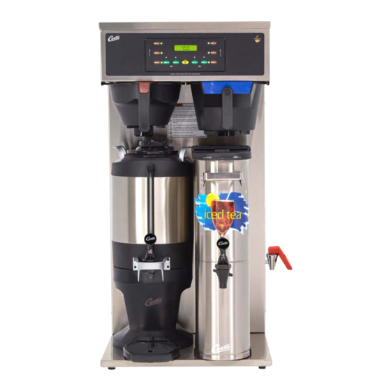
Curtis G3 User Manual
Digital high volume combo brewers
Hide thumbs
Also See for G3:
- User manual (60 pages) ,
- Specification sheet (4 pages) ,
- Brochure & specs (4 pages)

Related Manuals for Curtis G3


Summary of Contents for Curtis G3
- Page 1 G3 Digital High Volume Combo Brewers : Please leave this booklet with the machine. 022317A FC16 - CBHS/CBHT, FRONT COVER F-10015 revNC...
-
Page 2: Table Of Contents
........................ES21 ........................ES22 ........................................................................................EC4 ..............................Contact Information Wilbur Curtis Co., Inc. 6913 Acco Street | Montebello, CA 90640 US Phone: 323-837-2300 | Toll Free: 800-421-6150 Email: csrassistance@wilburcurtis.com | Web: www.wilburcurtis.com . - 4:00 . PT Email: techsupport@wilburcurtis.com CBHS/CBHT, CONTENTS LIST... -
Page 3: Fs16
KEY FEATURES/SPECIFICATIONS/SYSTEM REQUIREMENTS FS16 Key Features • • • • • 1800 W/ Single, High Volume, Combo Brewer 1 PH 110/220 V 15.0/12.7 A 2 X 1600 W 2W/3W + G 50/60 Hz 12.0 2800 W 5100 W/ Twin, High Volume, Combo Brewer 1 PH 220 V 23.0/34.0 A... -
Page 4: Is2
INSTRUCTIONS could result in personal injury or void the warranty. • This appliance is designed for commercial use. Any service other than cleaning and preventive maintenance should be performed by an authorized Wilbur Curtis service technician. • serviceable parts inside. - Page 5 IMPORTANT SAFEGUARDS CE Requirements • This appliance must be installed in locations where it can be overseen by trained personnel. • • • • This appliance must not be cleaned by water jet. • instruction concerning use of the appliance in a safe way and if they understand the hazards involved. •...
-
Page 6: Ii2
INSTALLATION INSTRUCTIONS WARNING: WARNING: properly grounded. NOTICE: SPECIFICATIONS section. IMPORTANT: Installation Instructions Installation Requirements • A secure surface capable of supporting the weight of the appliance. • For units without an attached cord set: Appropriately sized, UL listed, grounding type power cable to meet enough •... -
Page 7: Ii10
INSTALLATION INSTRUCTIONS II10 Installation Leveling WARNING: Use the leveling legs to level the brewer only. Do not use them to adjust brewer height. Do not extend them higher than necessary. Position the brewer on the countertop. Level it left to right and front to back by turning the bottom of the legs. - Page 8 INSTALLATION INSTRUCTIONS II10 Installation (cont.) Locate the hot water tube that runs from the hot water tank inside the brewer. It has a plug in the end of it. 10 Remove the plug from the hot water tube. 11 Slide the end of the hot water tube over the smooth section of the faucet shank inside the brewer, as far as it will go.
- Page 9 INSTALLATION INSTRUCTIONS II10 Brewers With A Cord Set Attached 21 Connect the power cord to the appropriate electrical outlet. WARNING: Connect the power cord to the appropriate type and size electrical outlet. If the electrical outlet is not compatible with the power cord, have it upgraded by a licensed electrician.
-
Page 10: Oi13
Do not remove the brew basket while “Brewing” appears on the display. WARNING - DO NOT refrigerate unused tea overnight for later consumption. The G3 Combo Brewer is factory preset for optimal performance. DISPENSER The brewer should be ON. -
Page 11: Ci1
CLEANING INSTRUCTIONS WARNING: HOT SURFACES - To avoid injury, allow the brewer and dispenser(s) to cool before cleaning. NOTICE - Do not use cleaning liquids, compounds or powders containing chlorine (bleach) or corrosives. USE OF THESE PRODUCTS WILL VOID THE WARRANTY. Cleaning The Brewer - Daily WARNING: DO NOT immerse the brewer in water or any other liquid. -
Page 12: Ci5
CLEANING INSTRUCTIONS Cleaning the 1.0 Gallon or 1.5 Gallon Thermal Dispensers (Daily) WARNING: DO NOT immerse the thermal server or its lid assembly in water or any other liquid. Do not place the thermal server or lid in a dishwasher. Placing a thermal server in a dishwasher will void the warranty. To avoid damage, DO NOT use a brush to clean the faucet or the inside of the faucet shank (outlet). - Page 13 CLEANING INSTRUCTIONS Cleaning the Faucet Parts and Gauge Glass (cont.) Sanitize - After rinsing, place all faucet and gauge parts in a sink to be sanitized. Immerse them in a commercial sanitizer suitable for food grade applications. Sanitize according to the W ASH directions on the package.
-
Page 14: Ci6
CLEANING INSTRUCTIONS Cleaning the Tea Dispenser (Daily) Cleaning the Container Prepare a mild solution of detergent and warm water. Remove the dispenser from the brewer and remove the lid. Rinse. Wash - Wipe the exterior surfaces with a sponge and the detergent solution to remove spills and debris. - Page 15 PROGRAMMING GUIDE Curtis To enter programming mode: With unit OFF, press and hold bottom right BREW button (4). Then press and release ON/OFF button (2). Continue to Entering Programming mode hold down BREW button until Enter Code appears. Enter Code - - - - Enter 4 digit code.
- Page 16 PROGRAMMING GUIDE PROGRAMMING MENUS After entering programming mode press to display the various programming menus: Press to enter the each individual programming menu. Detailed descriptions of each menu and the programmable features are below and on the following pages. Coffee Recipes Menu Sets coffee recipe.
- Page 17 PROGRAMMING GUIDE Non-Brew Program Menu (cont.) Service Call - sets the service phone number that appears on the display when the UCM detects a SENSOR ERROR or WATER ERROR. Once accessed ( ), press to select the number to be changed. Press to change the number value.
- Page 18 PROGRAMMING GUIDE Brew Button Program Menu (COFFEE, cont.) Brew by Time - sets the amount of coffee brewed according to time. Once accessed ( ), press the BREW button for which the brew time needs to be changed. Press to highlight minutes or seconds. Press to change the setting.
- Page 19 PROGRAMMING GUIDE Brew Button Program Menu (TEA, cont.) Tea Dilut. Volume - sets the tea dilution volume. Once accessed ( ), place an empty container under the (empty) brew basket, then press the BREW button for which the dilution volume needs to be changed. When been set.
- Page 20 ROUGH-IN DRAWINGS RD22 CBHS67000-001 2.0 in [5.1 cm] 3.73 in [9.5 cm] 36.71 in [93.2 cm] 0.48 in [1.2 cm] 12.50 in 9.11 in 10.33 in [31.8 cm] [23.1 cm] [26.2 cm] 16.61 in [42.2 cm] 25.63 in 23.68 in [65.1 cm] [60.1 cm] 23.13 in...
- Page 21 ROUGH-IN DRAWINGS RD23 CBHT17000-001 2.00 in [5.1 cm] 3.75 in 36.75 in [9.5 cm] [93.3 cm] 12.50 in 10.25 in [31.8 cm] 18.13 in [26.0 cm] [46.0 cm] 16.75 in [42.5 cm] 33.74 in [85.7 cm] 23.63 in [60.0 cm] Water Supply 23.63 in Connection...
- Page 22 ILLUSTRATED PARTS/RECOMMENDED PARTS IP16 Supplies and Accessories - All Models WC-29050 - Spray Head CAB-1 - Cleaning Brush (Purple) Sold by the case CBHS67000-001 - Main Chassis - Exploded View See section IP25...
-
Page 23: Ip16
LEG, 3/8”-16 STUD SCREW BUMPER WC-1412 CORD GRIP, 3/4” FOR METAL CORD TO .81”OD WC-13444 HARNESS, ADAPTER ASSY CBHVS WC-39846 LABEL, UCM OVERLAY COMBO SINGLE CURTIS O’RING, .426 X 9/16 O.D X .070 WALL EDPM KIT, HOT WATER FAUCET REPLACEMENT WC-43134 TCTS WC-37252... - Page 24 ILLUSTRATED PARTS/RECOMMENDED PARTS IP16 CBHT17000-001 - Main Chassis - Exploded View See section IP26...
- Page 25 WC-13335-101 HARNESS ASSY, COMPLETE CBHVT WC-1412 CORD GRIP, 3/4” FOR METAL CORD TO .81”OD O’RING, .426 X 9/16 O.D X .070 WALL EDPM WC-39845 LABEL, UCM OVERLAY COMBO TWIN CURTIS WC-43134 TCTS KIT, HOT WATER FAUCET REPLACEMENT WC-37252 WC-3518 LEG, GLIDE 3/8”-16 STUD SCREW...
-
Page 26: Ip25
ILLUSTRATED PARTS/RECOMMENDED PARTS IP25 WC-62080 - Tank Assembly WC-62080 - Tank Assembly - Parts List ITEM # PART # DESCRIPTION ITEM # PART # DESCRIPTION WC-54290DV-102 TANK, ASSY CBHS/CBHS67144 THERMOSTAT, HI LIMIT HEATER CONTROL WC-522 DPST 277V 40A WC-62080 TANK COMPLETE, CBHS/CBHS67144 WC-37365 KIT, FITTING TANK INLET WC-5853-102... -
Page 27: Ip26
ILLUSTRATED PARTS/RECOMMENDED PARTS IP26 WC-62033 - Tank Assembly WC-62033 - Tank Assembly - Parts List ITEM # PART # DESCRIPTION ITEM # PART # DESCRIPTION WC-54287 TANK, ASSY TPS1T/GEMTS WC-4382 GUARD, SHOCK HTNG ELMNT DOUBLE WC-62033 TANK, COMPLETE GEMTS W/ULTEM FITTINGS THERMOSTAT, HI LIMIT HEATER CONTROL DPST WC-522 277V 40A... -
Page 28: Es21
ELECTRICAL SCHEMATICS ES21 CBHS - 110/220 to 120/240 Volts UCM Pin Assignments 20 Pin Connector NOT USED SOLID STATE RELAY - COMMON SOLID STATE RELAY - +5 VDC NOT USED NOT USED INLET VALVE BYPASS VALVE NOT USED DILUTION VALVE NOT USED NOT USED NOT USED... -
Page 29: Es22
ELECTRICAL SCHEMATICS ES22 CBHT - 220 Volts CBHT, ELECTRICAL SCHEMATIC 091516NC... - Page 30 TROUBLESHOOTING GUIDE WARNING: Electric Shock Hazard - Scald and Burn Hazard - IMPORTANT: always check all Valve Test Procedure Troubleshooting Guidelines • • • • Valve Test Procedure in either direction Water Not Hot Enough replace the temperature sensor Water Heats More Slowly Than Usual...
- Page 31 If the UCM is operating normally, check for a false over-temp error caused by the temperature sensor. Check the resistance across the leads of the temperature sensor. If the resistance is less than 10 k when the water is cool, replace the temperature sensor. G3 BREWERS WITH SSR, TROUBLESHOOTING GUIDE 082316NC...
-
Page 32: Ec4
ERROR CODES System Fault Messages An error message will appear on the screen in the event of a malfunction under the following conditions: ERROR MESSAGE WARNING DESCRIPTION CAUSE Water Level Error G3 BREWER, ERROR CODES 042017A... - Page 33 Return Merchandise Authorization (RMA): All returned equipment must be properly re-packaged in the original carton and received by Curtis within 45 days following the issuance of a RMA. NO UNITS OR PARTS WILL BE ACCEPTED WITHOUT A RETURN MERCHANDISE AUTHORIZATION (RMA).
Need help?
Do you have a question about the G3 and is the answer not in the manual?
Questions and answers