
Related Manuals for WEG RUW-01


Summary of Contents for WEG RUW-01
- Page 1 Motors | Automation | Energy | Transmission & Distribution | Coatings CANopen Remote Unit RUW-01 Installation, Configuration and Operation Guide...
-
Page 3: Table Of Contents
Summary 1 SAFETY INSTRUCTIONS ................5 2 GENERAL INFORMATION ................ 5 3 PACKAGE CONTENTS ................5 4 INSTALLATION ................... 5 4.1 MECHANICAL INSTALLATION ..............6 4.2 ELECTRIC INSTALLATION ................6 4.3 CANOPEN NETWORK CONNECTION ............7 4.4 CONNECTION OF THE DIGITAL INPUTS ..........7 4.5 CONNECTION OF THE DIGITAL OUTPUTS ..........9 5 CONFIGURATION .................. -
Page 5: Safety Instructions
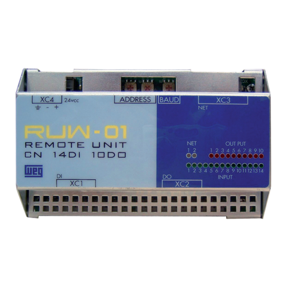
RUW-01 CN14DI10DO: it has 14 digital inputs and 10 digital outputs. It will be „ referred to in this guide as RUW-01.00. RUW-01 CN13DI: it has 13 digital inputs and has no digital outputs. It will be „ referred to in this guide as RUW-01.01. -
Page 6: Mechanical Installation
Figure 1: RUW01 installation 4.2 ELECTRIC INSTALLATION The RUW-01 is powered by an external 24 Vdc +/- 15 % power supply, with a current capacity of at least 500 mA. The protective earth must also be connected. The connection is done through the XC4 terminal strip. -
Page 7: Canopen Network Connection
CANopen Remote Unit 4.3 CANOPEN NETWORK CONNECTION The RUW-01 has a green LED to indicate that the interface is powered. The CAN communication module has a 5 pole plug-in terminal strip (XC3) with the following pinout: Table 1: CAN interface XC3 connector pinout... -
Page 8: Connection Of The Digital Inputs
24 Vdc, as per Figure 3.b. - (+) 24 Vcc + (-) (b) XC1: Power supply of the digital inputs of the RUW-01.01 Figure 3: (a) and (b) XC1: Activation of the digital inputs RUW-01.00 and RUW-01.01 8 | RUW-01 - English -... -
Page 9: Connection Of The Digital Outputs
Figure 4: XC2: Digital output wiring diagram RUW-01.00 RUW-01.01: The RUW-01.01 does not have digital outputs. 5 CONFIGURATION The RUW-01 configuration is done with hexadecimal switches with the following functions: S1 and S2: Configuration of the address in the CANopen network. „... -
Page 10: Canopen Network Address
CANopen Remote Unit Address selection Baud rate setting Figure 5: Hexadecimal switches for the RUW-01 configuration 5.1 CANOPEN NETWORK ADDRESS The remote unit address is configured through two hexadecimal switches, S1 and S2, as illustrated in the Figure 6. This address is used to identify the unit in the CANopen network. -
Page 11: Baud Rate Baud Rate
It allows programming the desired baud rate for the CAN interface, in bits per second. This baud rate must be the same for all the equipments connected to the network. The RUW-01 has a hexadecimal switch for the baud rate communication setting, as illustrated in the Figure 6. -
Page 12: Diagnosis
CANopen Remote Unit 6 DIAGNOSIS The RUW-01 presents diagnosis through LED’s that indicate the status of every digital input and output, and the communication status. Communication LED’s Digital output LED’s Digital input LED’s Figure 7: RUW-01 LED indications 6.1 COMMUNICATION DIAGNOSIS The communication presents two LED’s: CAN (NET 1) and ERROR (NET 2). -
Page 13: Diagnosis Of The Digital Inputs And Outputs
Constant red BUS OFF error CANopen network, normally associated to installation problems or incorrect baud rate configuration It is necessary to cycle the power of the RUW-01 „ BUS POWER It indicates that the CAN interface does not have power „... - Page 14 CANopen Remote Unit LED flashes every 50 ms LED flashes every 200 ms 1000 LED flashes once every second 1000 LED flashes twice every second Figure 8: LED indication behavior time diagram 14 | RUW-01 - English -...
- Page 15 NOTES...
- Page 17 WEG Drives & Controls - Automação LTDA. Jaraguá do Sul - SC - Brazil Phone 55 (47) 3276-4000 - Fax 55 (47) 3276-4020 São Paulo - SP - Brazil Phone 55 (11) 5053-2300 - Fax 55 (11) 5052-4212 automacao@weg.net 12813633...
Need help?
Do you have a question about the RUW-01 and is the answer not in the manual?
Questions and answers