
Related Manuals for MSI Wind Board D510 Series


Summary of Contents for MSI Wind Board D510 Series
- Page 1 Wind Board Wind Board D510 / D410 series D510 / D410 series MS-7618 (v1.x) Mini -ITX Mainboard G52-76181X1...
- Page 2 If a problem arises with your system and no solution can be obtained from the user’s manual, please contact your place of purchase or local distributor. Alternatively, please try the following help resources for further guidance. ◙ Visit the MSI website for FAQ, technical guide, BIOS updates, driver updates, and other information: http://www.msi.com/index.php?func=service http://www.msi.com/index.php?func=service ◙...
- Page 3 MS-7618 Safety Instructions Safety Instructions ■ Always read the safety instructions carefully. ■ Keep this User’s Manual for future reference. ■ Keep this equipment away from humidity. ■ Lay this equipment on a reliable fl at surface before setting it up. ■...
- Page 4 ▍ Preface Preface FCC-B Radio Frequency Interference Statement FCC-B Radio Frequency Interference Statement This equipment has been tested and found to comply with the limits for a Class B digi- tal device, pursuant to Part 15 of the FCC Rules. These limits are designed to provide reasonable protection against harmful inter- ference in a residential installation.
- Page 5 MSI will comply with the product take back requirements at the end of life of MSI-branded products that are sold into the EU.
- Page 6 MSI će poštovati zahtev o preuzimanju ovakvih proizvoda kojima je istekao vek trajanja, koji imaju MSI oznaku i koji su prodati u EU. Ove proiz- vode možete vratiti na lokalnim mestima za prikupljanje.
- Page 7 fi ne del suo ciclo di vita. MSI si adeguerà a tale Direttiva ritirando tutti i prodotti marchiati MSI che sono stati venduti all’interno dell’Unione Europea alla fi ne del loro...
-
Page 8: Table Of Contents
▍ Preface Preface CONTENTS CONTENTS ▍ Copyright Notice Copyright Notice ......................................i i i i Trademarks Trademarks ........................................i i i i Revision History Revision History......................................i i i i Technical Support Technical Support....................................i i i i Safety Instructions Safety Instructions .................. - Page 9 Chapter 1 Chapter 1 Getting Started Getting Started Thank you for choosing the Wind Board D510 / D410 Wind Board D510 / D410 Series (MS-7618 v1.X) Mini-ITX mainboard. The Wind Wind Board D510 / D410 Board D510 / D410 Series mainboards are based on In- NM10 NM10 chipset for optimal system effi...
-
Page 10: Mainboard Specifications
Memory Support Memory Support ■ DDR2 800 SDRAM (4GB Max) ■ 2 DDR2 DIMMs (240pin / 1.8V), single channel *(For more information on compatible components, please visit http://www.msi.com/index.php?func=testreport) ■ Supports Realtek RTL8103EL 10/100 Mb/s ® ■ Supports Realtek RTL8111DL 10/100/1000 Mb/s (optional) ®... - Page 11 MS-7618 Slots Slots ■ 1 PCI slot ■ Support 3.3V/ 5V PCI bus Interface Form Factor Form Factor ■ Mini-ITX (17.0cm X 17.0cm) Mounting Mounting ■ 6 mounting holes...
-
Page 12: Mainboard Layout
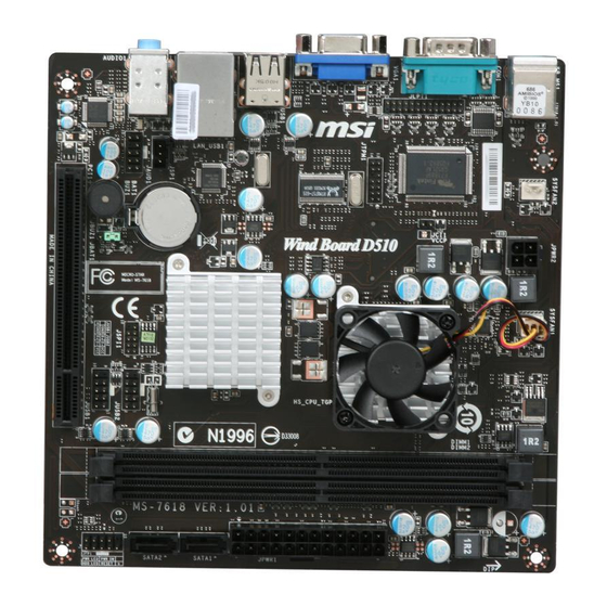
▍ Getting Started Getting Started AINBOARD AINBOARD AYOUT AYOUT SYSFAN1 Top : mouse Bottom: keyboard SYSFAN2 JPWR2 COM Port JCI1 Intel D510/D410 JTPM1 VGA port USB ports Intel NM10 Top: LAN Jack Bottom: USB ports JSP1 BATT T:Line-In M:Line- Out B:Mic-In JUSB2 JAUD1... -
Page 13: Packing Checklist
T:Line-In M:Line- Out B:Mic-In JAUD1 JUSB2 JBAT1 JUSB1 MSI Driver/Utility DVD MSI mainboard SATA Cable Back IO Shield USB Bracket (Optional) Power Cable User’s Guide * The pictures are for reference only and may vary from the packing contents of the product you purchased. - Page 15 Chapter 2 Chapter 2 Hardware Setup Hardware Setup This chapter provides you with the information about hardware setup procedures. While doing the installa- tion, be careful in holding the components and follow the installation procedures. For some components, if you install in the wrong orientation, the components will not work properly.
-
Page 16: Quick Components Guide
▍ Hardware Setup Hardware Setup UICK UICK OMPONENTS OMPONENTS UIDE UIDE JPWR2 JPWR2, p.2-5 JLPT1 JLPT1, p.2-10 JCI1 JCI1, p.2-8 JTPM1 JTPM1, p.2-10 SYSFAN2 SYSFAN2, SYSFAN1 SYSFAN1, DDR2 DDR2, p.2-3 p.2-8 p.2-8 JPWR1 JPWR1, p.2-5 Back Panel Back Panel, p.2-6 SATA SATA, p.2-7 JSP1... -
Page 17: Memory
MS-7618 EMORY EMORY These DIMM slots are used for installing memory modules. For more information on compatible components, please visit http://www.msi.com/index.php?func=testreport DDR2 DDR2 240-pin, 1.8V 240-pin, 1.8V 64x2=128 pin 64x2=128 pin 56x2=112 pin 56x2=112 pin Memory Population Rule Memory Population Rule Please refer to the following illustrations for memory population rules. - Page 18 ▍ Hardware Setup Hardware Setup Installing Memory Modules Installing Memory Modules The memory module has only one notch on the center and will only fi t in the right orientation. Insert the memory module vertically into the DIMM slot. Then push it in until the golden fi...
-
Page 19: Power Supply
MS-7618 OWER OWER UPPLY UPPLY ATX 24-pin Power Connector: JPWR1 ATX 24-pin Power Connector: JPWR1 This connector allows you to connect an ATX 24-pin power supply. To connect the ATX 24-pin power supply, make sure the plug of the power supply is inserted in the proper orientation and the pins are aligned. -
Page 20: Back Panel
▍ Hardware Setup Hardware Setup ANEL ANEL Line-In Line-In Mouse Mouse Line-Out Line-Out VGA Port VGA Port USB Port USB Port Serial Port Serial Port USB Port USB Port Keyboard Keyboard ▶ Mouse/Keyboard Mouse/Keyboard The standard PS/2 mouse/keyboard DIN connector is for a PS/2 mouse/keyboard. -
Page 21: Connectors
MS-7618 ONNECTORS ONNECTORS Serial ATA Connectors: SATA1~2 Serial ATA Connectors: SATA1~2 This connector is a high-speed Serial ATA interface port. Each connector can connect to one Serial ATA device. Important Important Please do not fold the Serial ATA cable into 90-degree angle. Otherwise, data loss may occur during transmission. - Page 22 ▍ Hardware Setup Hardware Setup Chassis Intrusion Connector: JCI1 Chassis Intrusion Connector: JCI1 This connector connects to the chassis intrusion switch cable. If the chassis is opened, the chassis intrusion mechanism will be activated. The system will record this status and show a warning message on the screen.
- Page 23 MS-7618 Front USB Connector: JUSB1 / JUSB2 Front USB Connector: JUSB1 / JUSB2 This connector, compliant with Intel I/O Connectivity Design Guide, is ideal for con- ® necting high-speed USB interface peripherals such as USB HDD, digital cameras, MP3 players, printers, modems and the like. USB 2.0 Bracket (optional) Important Important...
- Page 24 ▍ Hardware Setup Hardware Setup TPM Module connector: JTPM1 TPM Module connector: JTPM1 This connector connects to a TPM (Trusted Platform Module) module. Please refer to the TPM security platform manual for more details and usages. Parallel Port Header: JLPT1 Parallel Port Header: JLPT1 This connector is used to connect an optional parallel port bracket.
- Page 25 MS-7618 S/PDIF-Out Connector: JSP1 S/PDIF-Out Connector: JSP1 This connector is used to connect S/PDIF (Sony & Philips Digital Interconnect Format) interface for digital audio transmission. S/PDIF Bracket (Optional) 2-11...
-
Page 26: Jumpers
▍ Hardware Setup Hardware Setup UMPERS UMPERS Clear CMOS Jumper: JBAT1 Clear CMOS Jumper: JBAT1 There is a CMOS RAM onboard that has a power supply from an external battery to keep the data of system confi guration. With the CMOS RAM, the system can automati- cally boot OS every time it is turned on. -
Page 27: Slots
MS-7618 LOTS LOTS PCI (Peripheral Component Interconnect) Slot PCI (Peripheral Component Interconnect) Slot The PCI slot supports LAN card, SCSI card, USB card, and other add-on cards that comply with PCI specifi cations. 32-bit PCI Slot Important Important When adding or removing expansion cards, make sure that you unplug the power sup- ply fi... - Page 29 Chapter 3 Chapter 3 BIOS Setup BIOS Setup This chapter provides information on the BIOS Setup program and allows you to confi gure the system for op- timum use. You may need to run the Setup program when: ■ An error message appears on the screen during the system booting up, and requests you to run SETUP.
-
Page 30: Entering Setup
▍ BIOS Setup BIOS Setup NTERING NTERING ETUP ETUP Power on the computer and the system will start POST (Power On Self Test) process. When the message below appears on the screen, press <DEL> key to enter Setup. Press DEL to enter SETUP Press DEL to enter SETUP If the message disappears before you respond and you still wish to enter Setup, restart the system by turning it OFF and On or pressing the RESET button. - Page 31 MS-7618 Control Keys Control Keys <↑> Move to the previous item <↓> Move to the next item <←> Move to the item in the left hand <→> Move to the item in the right hand <Enter> Select the item <Esc> Jumps to the Exit menu or returns to the main menu from a submenu <+/PU>...
-
Page 32: The Main Menu
▍ BIOS Setup BIOS Setup ▶ Standard CMOS Features Standard CMOS Features Use this menu for basic system confi gurations, such as time, date etc. ▶ Advanced BIOS Features Advanced BIOS Features Use this menu to setup the items of the BIOS special enhanced features. ▶... - Page 33 MS-7618 ▶ M-Flash M-Flash Use this menu to read/ fl ash the BIOS from storage drive (FAT/ FAT32 format only). ▶ Load Fail-Safe Defaults Load Fail-Safe Defaults Use this menu to load the default values set by the BIOS vendor for stable system performance.
-
Page 34: Standard Cmos Features
▍ BIOS Setup BIOS Setup CMOS F CMOS F TANDARD TANDARD EATURES EATURES The items in Standard CMOS Features Menu include some basic setup items. Use the arrow keys to highlight the item and then use the <PgUp> or <PgDn> keys to select the value you want in each item. - Page 35 MS-7618 ▶ SATA1~2 SATA1~2 Press <Enter> to enter the sub-menu and the following screen appears: ▶ Device / Vendor / Size Device / Vendor / Size It will show the device information that you connected to the SATA connector. ▶ LBA/Large Mode LBA/Large Mode This allows you to enable or disable the LBA Mode.
-
Page 36: Advanced Bios Features
▍ BIOS Setup BIOS Setup BIOS F BIOS F DVANCED DVANCED EATURES EATURES ▶ Boot Sequence Boot Sequence Press <Enter> to enter the sub-menu. ▶ 1st/ 2nd Boot Device 1st/ 2nd Boot Device These items allow you to set the fi rst/ second/ third boot device where BIOS at- tempts to load the disk operating system. - Page 37 MS-7618 ▶ Quick Booting Quick Booting Setting the item to [Enabled] allows the system to boot within 10 seconds since it will skip some check items. ▶ Boot Up Num-Lock LED Boot Up Num-Lock LED This setting is to set the Num Lock status when the system is powered on. Setting to [On] will turn on the Num Lock key when the system is powered on.
-
Page 38: Integrated Peripherals
▍ BIOS Setup BIOS Setup NTEGRATED NTEGRATED ERIPHERALS ERIPHERALS ▶ USB Controller USB Controller This setting allows you to enable/disable the onboard USB controller. ▶ USB Device Legacy Support USB Device Legacy Support Select [Enabled] if you need to use a USB-interfaced device in the operating system. ▶... - Page 39 MS-7618 ▶ PCI IDE BusMaster PCI IDE BusMaster This item allows you to enable/ disable BIOS to used PCI busmastering for reading/ writing to IDE drives. ▶ On-Chip SATA Controller On-Chip SATA Controller This item allows users to enable or disable the on-chip SATA controller. ▶...
-
Page 40: Power Management Setup
▍ BIOS Setup BIOS Setup OWER OWER ANAGEMENT ANAGEMENT ETUP ETUP Important Important S3-related functions described in this section are available only when the BIOS sup- ports S3 sleep mode. ▶ ACPI Function ACPI Function This item is to activate the ACPI (Advanced Confi guration and Power Management Interface) Function. - Page 41 MS-7618 ▶ Restore On AC Power Loss Restore On AC Power Loss This item specifi es whether your system will reboot after a power failure or interrupt occurs. Settings are: [Off ] Always leaves the computer in the power off state. [On] Always leaves the computer in the power on state.
-
Page 42: H/W Monitor
▍ BIOS Setup BIOS Setup H/W M H/W M ONITOR ONITOR ▶ Chassis Intrusion Chassis Intrusion The fi eld enables or disables the feature of recording the chassis intrusion status and issuing a warning message if the chassis is once opened. To clear the warning mes- sage, set the fi... -
Page 43: Bios Setting Password
MS-7618 BIOS S BIOS S ETTING ETTING ASSWORD ASSWORD When you select this function, a message as below will appear on the screen: ▶ U-Key U-Key This item is used to enable/ disable USB driver device as a key. ▶ Make U-Key at Make U-Key at This item is used to specify the USB driver device as a key. - Page 44 ▍ BIOS Setup BIOS Setup Important Important Type the password, up to eight characters in length, and press <Enter>. The password typed now will replace any previously set password. You will be prompted to confi rm the password. Retype the password and press <Enter>. You may also press <Esc> to abort the selection and not enter a password.
-
Page 45: Cell Menu
MS-7618 Important Important Change these settings only if you are familiar with the chipset. ▶ Current CPU / DRAM Frequency Current CPU / DRAM Frequency These items show the current frequencies of CPU and Memory. Read-only. ▶ CPU Specifi cations CPU Specifi... - Page 46 ▍ BIOS Setup BIOS Setup ▶ CPU Technology Support CPU Technology Support Press <Enter> to enter the sub-menu. In this sub-menu, it shows the installed CPU technologies. Read only. ▶ CPU Feature CPU Feature Press <Enter> to enter the sub-menu and the following screen appears: ▶...
- Page 47 MS-7618 ▶ Memory-Z Memory-Z Press <Enter> to enter the sub-menu and the following screen appears. ▶ DIMM1~2 Memory SPD Information DIMM1~2 Memory SPD Information Press <Enter> to enter the sub-menu. The sub-menu displays the informations of installed memory. ▶ Advance DRAM Confi guration Advance DRAM Confi...
- Page 48 ▍ BIOS Setup BIOS Setup ▶ tRCD tRCD When DRAM is refreshed, both rows and columns are addressed separately. This setup item allows you to determine the timing of the transition from RAS (row ad- dress strobe) to CAS (column address strobe). The less the clock cycles, the faster the DRAM performance.
-
Page 49: M-Flash
MS-7618 LASH LASH == BIOS Update or Boot 2nd BIOS From USB drive== ▶ M-Flash function as M-Flash function as M-Flash function allows you to fl ash BIOS from USB drive/ storage drive (FAT/ FAT32 format only), or allows the system to boot from the BIOS fi le inside USB drive (FAT/ FAT32 format only). - Page 50 ▍ BIOS Setup BIOS Setup Important Important • Please refer to the block diagram below about the M-Flash function. Due to the special design of some graphics cards will cause dark screen during M- • fl ash operation, and you may refer the beeps from the system to confi rm the current M-fl...
- Page 51 MS-7618 == Backup BIOS to USB drive == The following fi elds are used to read the onboard BIOS ROM data, and save it to USB drive/ storage drive. ▶ Save File to Selected Device Save File to Selected Device Please setup a specifi...
-
Page 52: Load Fail-Safe/ Optimized Defaults
▍ BIOS Setup BIOS Setup PTIMIZED PTIMIZED EFAULTS EFAULTS The two options on the main menu allow users to restore all of the BIOS settings to the default Fail-Safe or Optimized values. The Optimized Defaults are the default values set by the mainboard manufacturer specifi...
Need help?
Do you have a question about the Wind Board D510 Series and is the answer not in the manual?
Questions and answers