MSI MAG B660 TOMAHAWK WIFI DDR4 Quick Start Manual
Hide thumbs
Also See for MAG B660 TOMAHAWK WIFI DDR4:
- User manual ,
- Quick start manual (164 pages) ,
- User manual
Table of Contents
Advertisement
Quick Links
Quick Start
Thank you for purchasing the MSI®
This Quick Start section provides demonstration diagrams about how to install your
computer. Some of the installations also provide video demonstrations. Please link to
the URL to watch it with the web browser on your phone or tablet. You may have even
link to the URL by scanning the QR code.
Preparing Tools and Components
Intel® LGA1700 CPU
DDR4 Memory
Thermal Paste
Phillips Screwdriver
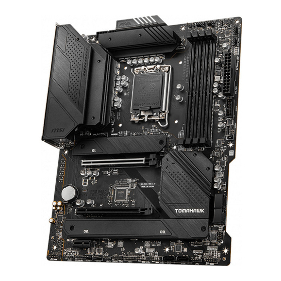
MAG B660 TOMAHAWK WIFI DDR4
LGA1700 CPU Fan
Power Supply Unit
SATA Hard Disk Drive
Graphics Card
SATA DVD Drive
A Package of Screws
motherboard.
Chassis
1
Quick Start
Advertisement
Table of Contents

Related Manuals for MSI MAG B660 TOMAHAWK WIFI DDR4


Summary of Contents for MSI MAG B660 TOMAHAWK WIFI DDR4
-
Page 1: Quick Start
Quick Start Thank you for purchasing the MSI® MAG B660 TOMAHAWK WIFI DDR4 motherboard. This Quick Start section provides demonstration diagrams about how to install your computer. Some of the installations also provide video demonstrations. Please link to the URL to watch it with the web browser on your phone or tablet. You may have even link to the URL by scanning the QR code. -
Page 2: Safety Information
Safety Information ∙ The components included in this package are prone to damage from electrostatic discharge (ESD). Please adhere to the following instructions to ensure successful computer assembly. ∙ Ensure that all components are securely connected. Loose connections may cause the computer to not recognize a component or fail to start. -
Page 3: Case Stand-Off Notification
Case stand-off notification To prevent damage to the motherboard, any unnecessary mounting stand-off between the motherboard circuits and the computer case is prohibited. The Case standoff keep out zone signs will be marked on the backside of motherboard (as shown below) to serve as a warning to user. -
Page 4: Installing A Processor
Installing a Processor ⚽ https://youtu.be/KMf9oIDsGes Quick Start... -
Page 5: Installing Ddr4 Memory
Installing DDR4 memory ⚽ http://youtu.be/T03aDrJPyQs DIMMA1 DIMMA2 DIMMA2 DIMMA2 DIMMB1 DIMMB2 DIMMB2 Quick Start... -
Page 6: Connecting The Front Panel Header
Connecting the Front Panel Header ⚽ http://youtu.be/DPELIdVNZUI Power LED Power Switch JFP1 Reserved HDD LED Reset Switch HDD LED + Power LED + HDD LED - Power LED - Reset Switch Power Switch JFP1 Reset Switch Power Switch Reserved No Pin HDD LED - HDD LED HDD LED +... -
Page 7: Installing The Motherboard
Installing the Motherboard ⚽ https://youtu.be/wWI6Qt51Wnc Torque: 3 kgf·cm* BAT1 *3 kgf·cm = 0.3 N·m = 2.6 lbf·in Quick Start... -
Page 8: Connecting The Power Connectors
Connecting the Power Connectors ⚽ http://youtu.be/gkDYyR_83I4 ATX_PWR1 CPU_PWR2 CPU_PWR1 Quick Start... -
Page 9: Installing Sata Drives
Installing SATA Drives ⚽ http://youtu.be/RZsMpqxythc Quick Start... -
Page 10: Installing A Graphics Card
Installing a Graphics Card ⚽ http://youtu.be/mG0GZpr9w_A Quick Start... -
Page 11: Connecting Peripheral Devices
Connecting Peripheral Devices Quick Start... -
Page 12: Power On
Power On Quick Start... -
Page 13: Table Of Contents
Contents Quick Start ......................1 Preparing Tools and Components................1 Safety Information ....................2 Case stand-off notification ..................3 Avoid collision notification ..................3 Installing a Processor .................... 4 Installing DDR4 memory ..................5 Connecting the Front Panel Header ..............6 Installing the Motherboard .................. - Page 14 JBAT1: Clear CMOS (Reset BIOS) Jumper ............44 Onboard LEDs ...................... 44 EZ Debug LED ....................... 44 Installing OS, Drivers & MSI Center ..............45 Installing Windows 10/ Windows 11 ..............45 Installing Drivers ....................45 MSI Center ......................45 UEFI BIOS ......................
-
Page 15: Specifications
Specifications ∙ Supports 12th Gen Intel® Core™ Processors, Pentium® Gold and Celeron® Processors ∙ Processor socket LGA1700 * Please go to www.msi.com to get the newest support status as new processors are released. Chipset Intel® B660 Chipset ∙ 4x DDR4 memory slots, supporting up to 128GB* ∙... - Page 16 Continued from previous column ∙ 6x SATA 6Gb/s ports ▪ SATA5~8 (From B660 chipset) ▪ SATAA~B (From ASM1061) ∙ 3x M.2 slots (Key M) ▪ M2_1 slot (From CPU) ▫ Supports up to PCIe 4.0 x4 ▫ Supports 2242/ 2260/ 2280/ 22110 storage devices ▪...
- Page 17 Continued from previous column 1x Realtek® RTL8125B-CG 2.5Gbps LAN controller Intel® Wi-Fi 6 ∙ The Wireless module is pre-installed in the M.2 (Key-E) slot Wireless LAN & ∙ Supports MU-MIMO TX/RX, 2.4GHz/ 5GHz (160MHz) up to Bluetooth® 2.4Gbps ∙ Supports 802.11 a/ b/ g/ n/ ac/ ax ∙...
- Page 18 ∙ ACPI 6.4, SMBIOS 3.4 ∙ Multi-language ∙ Drivers ∙ MSI Center ∙ Intel Extreme Tuning Utility ∙ MSI APP Player (BlueStacks) Software ∙ Open Broadcaster Software (OBS) ∙ CPU-Z MSI GAMING ∙ Google Chrome™, Google Toolbar, Google Drive ∙ Norton™ Internet Security Solution...
- Page 19 ∙ Ambient Devices ∙ Frozr AI Cooling MSI Center ∙ User Scenario Features ∙ True Color ∙ Live Update ∙ Hardware Monitoring ∙ Super Charger ∙ Speed Up ∙ Smart Image Finder ∙ MSI Companion Continued on next column Specifications...
- Page 20 Continued from previous column ∙ Audio ▪ Audio Boost ▪ Sound Tune ∙ Network ▪ 2.5G LAN ▪ LAN Manager ▪ Intel Wi-Fi ∙ Cooling ▪ All Aluminum Design ▪ Extended Heatsink Design Special Features ▪ M.2 Shield Frozr ▪ Pump Fan ▪...
- Page 21 ▪ SUPPLEMENTAL PCIE POWER CONNECTOR ▪ 2oz Copper thickened PCB ∙ Protection ▪ PCI-E Steel Armor ▪ Pre-installed I/O Shielding ∙ Experience ▪ MSI Center ▪ Click BIOS 5 ▪ CPU Cooler Tuning ▪ EZ M.2 Clip ▪ App player ▪ Tile...
-
Page 22: Package Contents
Package contents Please check the contents of your motherboard package. It should contain: Motherboard MAG B660 TOMAHAWK WIFI DDR4 User manual Documentation Quick installation guide MSI reward program card Application Driver DVD Cables SATA 6Gb/s cables Wi-Fi antenna Case badge M.2 screw + standoff (2 sets/pack) -
Page 23: Block Diagram
Block Diagram PCI_E1 PCIe 4.0 x16 DDR4 2Channel DIMM A1/A2 DIMM B1/B2 M2_1 DMI x4 PCI_E2 PCIe 3.0 x4 USB3.2 Gen2x2 20Gbps PCI_E3 PCIe 3.0 x1 USB 3.2 Gen 2 10Gbps M2_2 SATA7 M2_3 USB 3.2 Gen 1 5Gbps SATA5/6/8 USB 2.0 SATAA/B ASM1061... -
Page 24: Rear I/O Panel
Rear I/O Panel Wi-Fi Antenna USB 2.0 connectors Audio Ports Type-A 2.5Gbps LAN DisplayPort Optical USB 3.2 USB 3.2 S/PDIF-Out Gen 2x2 Gen 2 (20Gbps) (10Gbps) Type-C Type-A LAN Port LED Status Table Link/ Activity LED Speed LED Status Description Status Description No link... -
Page 25: Realtek Audio Console
Realtek Audio Console After Realtek Audio Console is installed. You can use it to change sound settings to get better sound experience. Application Enhancement Device Selection Main Volume Connector Settings Jack Status ∙ Device Selection - allows you to select a audio output source to change the related options. - Page 26 Audio jacks to headphone and microphone diagram Audio jacks to stereo speakers diagram AUDIO INPUT Audio jacks to 7.1-channel speakers diagram AUDIO INPUT Rear Front Side Center/ Subwoofer Rear I/O Panel...
- Page 27 Installing antennas 1. Screw the antennas tight to the antenna connectors as shown below. 2. Orient the antennas. Rear I/O Panel...
-
Page 28: Overview Of Components
Overview of Components JRGB2 CPU_PWR1 PUMP_FAN1 Processor Socket CPU_FAN1 JRAINBOW1 CPU_PWR2 SYS_FAN1 SYS_FAN2 ATX_PWR1 JUSB3 SYS_FAN5 JUSB4 M2_1 DIMMB2 DIMMB1 PCI_E1 DIMMA2 DIMMA1 BAT1 SATA ▼ 5 ▲ 6 JBAT1 PCI_E2 SATA ▼ 7 ▲ 8 M2_3 M2_2 JTPM1 JCI1 PCI_E3 JAUD1 JFP1... - Page 29 Component Contents Port Name Port Type Page CPU_FAN1, PUMP_FAN1, Fan Connectors SYS_FAN1~5 CPU_PWR1~2, ATX_PWR1 Power Connectors CPU Socket LGA1700 CPU Socket DIMM Slots Memory slots JAUD1 Front Audio Connector JBAT1 Clear CMOS (Reset BIOS) Jumper JCI1 Chassis Intrusion Connector JDASH1 Tuning Controller connector JFP1, JFP2 Front Panel Connectors...
-
Page 30: Cpu Socket
∙ the CPU. ∙ Please retain the CPU protective cap after installing the processor. MSI will deal with Return Merchandise Authorization (RMA) requests if only the motherboard comes with the protective cap on the CPU socket. When installing a CPU, always remember to install a CPU heatsink. A CPU heatsink ∙... -
Page 31: Dimm Slots
It is recommended to use a more efficient memory cooling system for full DIMMs ∙ installation or overclocking. The stability and compatibility of installed memory module depend on installed CPU ∙ and devices when overclocking. ∙ Please refer to www.msi.com for more information on compatible memory. Overview of Components... -
Page 32: Pci_E1~3: Pcie Expansion Slots
Important ∙ If you install a large and heavy graphics card, you need to use a tool such as MSI Graphics Card Bolster to support its weight to prevent deformation of the slot. For a single PCIe x16 expansion card installation with optimum performance, using ∙... -
Page 33: M2_1~3: M.2 Slots (Key M)
M2_1~3: M.2 Slots (Key M) ⚠ Important ∙ Intel® RST only supports PCIe M.2 SSD with UEFI ROM. M2_2~3 slots support Intel® Optane™ ∙ Memory. M2_1 M2_3 M2_2 M.2 slot installation 1. Loosen the screws of M.2 SHIELD FROZR heatsink. 2. - Page 34 3. If there is no EZ M.2 clip installed, please install the supplied EZ M.2 clip kit in the M.2 slot according to your SSD length. 4. Insert your M.2 SSD into the M.2 slot at a 30-degree angle. 5. Rotate the EZ M.2 clip to fix the M.2 SSD. 30º...
-
Page 35: Sata5~8 & Sataa~B: Sata 6Gb/S Connectors
SATA5~8 & SATAA~B: SATA 6Gb/s Connectors These connectors are SATA 6Gb/s interface ports. Each connector can connect to one SATA device. SATAA SATA6 SATA5 SATAB SATA8 SATA7 ⚠ Important Please do not fold the SATA cable at a 90-degree angle. Data loss may result during ∙... -
Page 36: Cpu_Pwr1~2, Atx_Pwr1: Power Connectors
CPU_PWR1~2, ATX_PWR1: Power Connectors These connectors allow you to connect an ATX power supply. CPU_PWR1~2 Ground +12V Ground +12V Ground +12V Ground +12V +3.3V +3.3V +3.3V -12V Ground Ground PS-ON# Ground Ground Ground ATX_PWR1 Ground Ground PWR OK 5VSB +12V +12V +3.3V Ground... -
Page 37: Jdash1 : Tuning Controller Connector
JDASH1 : Tuning Controller connector This connector is used to connect an optional Tuning Controller module. No Pin MCU_SMB_SCL_M MCU_SMB_SDA_M VCC5 Ground JTPM1: TPM Module Connector This connector is for TPM (Trusted Platform Module). Please refer to the TPM security platform manual for more details and usages. -
Page 38: Jusb4: Usb 3.2 Gen 2 Type-C Connector
JUSB4: USB 3.2 Gen 2 Type-C Connector This connector allows you to connect USB 3.2 Gen 2 Type-C connector on the front panel. The connector possesses a foolproof design. When you connect the cable, be sure to connect it with the corresponding orientation. USB Type-C Cable JUSB4 USB Type-C port on... -
Page 39: Jusb1~2: Usb 2.0 Connectors
Note that the VCC and Ground pins must be connected correctly to avoid possible ∙ damage. ∙ In order to recharge your iPad, iPhone and iPod through USB ports, please install MSI Center utility. JTBT1: Thunderbolt Add-on Card Connector This connector allows you to connect the add-on Thunderbolt I/O card. TBT_FORCE_PWR TBT_S0IX_ENTRY_REQ... -
Page 40: Cpu_Fan1, Pump_Fan1, Sys_Fan1~5: Fan Connectors
CPU_FAN1, PUMP_FAN1, SYS_FAN1~5: Fan Connectors Fan connectors can be classified as PWM (Pulse Width Modulation) Mode or DC Mode. PWM Mode fan connectors provide constant 12V output and adjust fan speed with speed control signal. DC Mode fan connectors control fan speed by changing voltage. However, you can follow the instruction below to adjust the fan connector to PWM or DC Mode manually. -
Page 41: Jci1: Chassis Intrusion Connector
JCI1: Chassis Intrusion Connector This connector allows you to connect the chassis intrusion switch cable. Normal Trigger the chassis (default) intrusion event Using chassis intrusion detector 1. Connect the JCI1 connector to the chassis intrusion switch/ sensor on the chassis. 2. -
Page 42: Jrgb1~2: Rgb Led Connectors
(12V/G/R/B) with the maximum power rating of 3A (12V). Always turn off the power supply and unplug the power cord from the power outlet ∙ before installing or removing the RGB LED strip. Please use MSI’s software to control the extended LED strip. ∙ Overview of Components... -
Page 43: Jrainbow1~2: Addressable Rgb Led Connectors
(5V). In the case of 20% brightness, the connector supports up to 200 LEDs. ∙ Always turn off the power supply and unplug the power cord from the power outlet before installing or removing the RGB LED strip. Please use MSI’s software to control the extended LED strip. ∙ Overview of Components... -
Page 44: Jbat1: Clear Cmos (Reset Bios) Jumper
JBAT1: Clear CMOS (Reset BIOS) Jumper There is CMOS memory onboard that is external powered from a battery located on the motherboard to save system configuration data. If you want to clear the system configuration, set the jumpers to clear the CMOS memory. Keep Data Clear CMOS/ (default) -
Page 45: Installing Os, Drivers & Msi Center
MSI Center is an application that helps you easily optimize game settings and smoothly use content creation softwares. It also allows you to control and synchronize LED light effects on PCs and other MSI products. With MSI Center, you can customize ideal modes, monitor system performance, and adjust fan speed. -
Page 46: Uefi Bios
UEFI has many new functions and advantages that traditional BIOS cannot achieve, and it will completely replace BIOS in the future. The MSI UEFI BIOS uses UEFI as the default boot mode to take full advantage of the new chipset’s capabilities. -
Page 47: Bios Setup
* When you press F10, a confirmation window appears and it provides the modification information. Select between Yes or No to confirm your choice. BIOS User Guide If you’d like to know more instructions on setting up the BIOS, please refer to http://download.msi.com/manual/mb/Intel600BIOS.pdf or scan the QR code to access. UEFI BIOS... -
Page 48: Resetting Bios
Updating BIOS Updating BIOS with M-FLASH Before updating: Please download the latest BIOS file that matches your motherboard model from MSI website. And then save the BIOS file into the USB flash drive. Updating BIOS: 1. Switch to the target BIOS ROM by Multi-BIOS switch. Please skip this step if your motherboard doesn't has this switch. - Page 49 ∙ Please close all other application software before updating the BIOS. To update BIOS: 1. Install and launch MSI Center and go to Support page. 2. Select Live Update and click on Advance button. 3. Select the BIOS file and click on Install button.
-
Page 50: Raid Configuration
All the information/ volumes/ pictures listed in your system might differ from the illustrations in this appendix. Intel RAID User Guide If you’d like to know more instructions on how to set up Intel RAID, please refer to http://download.msi.com/manual/mb/IntelRAID600.pdf or scan the QR code to access. RAID Configuration... -
Page 51: Intel® Optane™ Memory Configuration
Intel® Optane™ Memory User Guide If you’d like to know more instructions on how to enable or remove Intel® Optane™ Memory, please refer to http://download.msi.com/manual/mb/Optane600.pdf or scan the QR code to access. ⚠ WARNING After you enable Intel® Optane™ memory, please note the following to prevent damage to your operating system. -
Page 52: Troubleshooting
Troubleshooting Lost BIOS password Before sending the motherboard for RMA repair, try to go over troubleshooting ∙ Clear the CMOS, but that will cause guide first to see if your got similar you to lose all customized settings in the symptoms as mentioned below. - Page 53 The point of contact for regulatory matters is MSI, MSI-NL Eindhoven 5706 5692 ER Son. y Visit the MSI website and locate a nearby distributor for further recycling information. KC인증서 y Users may also reach us at gpcontdev@msi.com for 상호: (주)엠에스아이코리아...
- Page 54 MSI will comply with the product take entregar a una empresa autorizada para la recogida de back requirements at the end of life of MSI-branded estos residuos.
- Page 55 MSI si adeguerà a tale Direttiva indicated in instructions specific to the product. ritirando tutti i prodotti marchiati MSI che sono stati venduti all’interno dell’Unione Europea alla fine del...
- Page 56 Copyright © 2021 All rights reserved. contact your place of purchase or local distributor. The MSI logo used is a registered trademark of Alternatively, please try the following help resources Micro-Star Int’l Co., Ltd. All other marks and names for further guidance.
Need help?
Do you have a question about the MAG B660 TOMAHAWK WIFI DDR4 and is the answer not in the manual?
Questions and answers