Table of Contents
Advertisement
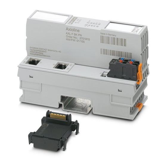
AXL F BK PN
Axioline F bus coupler for PROFINET
Data sheet
105731_en_01
1
Description
The bus coupler links a PROFINET network with the
Axioline F system.
You can connect up to 63 Axioline F devices to an existing
PROFINET system with the help of the bus coupler.
This data sheet is only valid in association with the UM EN AXL F SYS INST user manual.
For information on PROFINET basics, please refer to the UM EN PROFINET SYS user manual.
Make sure you always use the latest documentation.
It can be downloaded from the product at phoenixcontact.net/products.
Here you will also find the current GSDML file.
© PHOENIX CONTACT
2014-08-26
Features
–
Up to 63 additional Axioline F devices can be connect-
ed
–
2 Ethernet ports (with integrated switch)
–
Typical cycle time of the Axioline F local bus is around
10 s
–
PROFINET RT and IRT
–
PROFIsafe support
–
Minimum cycle time of PROFINET for RT and IRT is
250 s
–
Runtime in the bus coupler is negligible (goes to 0 μs)
–
Firmware can be updated
–
MRP-Client
–
Web-based management
–
I&M 1-4
–
Shared device
–
Diagnostic and status indicators
www.phoenixpowersupply.co.uk
Advertisement
Table of Contents

Related Manuals for Phoenix Contact AXL F BK PN


Summary of Contents for Phoenix Contact AXL F BK PN
-
Page 1: Description
AXL F BK PN Axioline F bus coupler for PROFINET Data sheet 105731_en_01 © PHOENIX CONTACT 2014-08-26 Description The bus coupler links a PROFINET network with the Features Axioline F system. – Up to 63 additional Axioline F devices can be connect- You can connect up to 63 Axioline F devices to an existing PROFINET system with the help of the bus coupler. -
Page 2: Table Of Contents
AXL F BK PN Table of contents Description ..........................1 Table of contents ........................2 Ordering data .......................... 3 Technical data ......................... 4 Internal circuit diagram ......................6 Connecting PROFINET and supply ..................7 ......................7 Connecting PROFINET ............. 7 Connecting the supply voltage - terminal point assignment Connection example........................ -
Page 3: Ordering Data
AXL F BK PN Ordering data Description Type Order No. Pcs. / Pkt. Axioline F bus coupler for PROFINET (including bus base module and con- AXL F BK PN 2701815 nector) Accessories Type Order No. Pcs. / Pkt. Axioline F bus base module for housing type BK (Replacement item) -
Page 4: Technical Data
AXL F BK PN Technical data Dimensions (nominal sizes in mm) Width 45 mm Height 125.9 mm Depth 74 mm Note on dimensions The depth is valid when a TH 35-7.5 DIN rail is used (according to EN 60715). General data... - Page 5 AXL F BK PN Interface Service Number Connection method Micro USB type B System limits Number of supported devices max. 63 (per station) NOTE: Electronics may be damaged when overloaded Observe the logic current consumption of each device when configuring an Axioline F station. It is specified in every module-specific data sheet.
-
Page 6: Internal Circuit Diagram
AXL F BK PN Internal circuit diagram PROFINET RJ45 RJ45 3.3V Service Reset Local bus 3.3 V 24 V 24 V Figure 1 Internal wiring of the terminal points Key: Functional earth ground Service Service interface Reset Reset button Local bus Axioline F local bus... -
Page 7: Connecting Profinet And Supply
AXL F BK PN Connecting PROFINET and supply Observe bending radii The housing dimensions specified under "Di- Connecting PROFINET mensions" refer to the bus coupler with I/O connectors without Ethernet connection. Connect PROFINET to the bus coupler via an 8-pos. RJ45 When installing the bus coupler in a control connector. -
Page 8: Local Status And Diagnostic Indicators
AXL F BK PN Local status and diagnostic indicators Figure 5 Local status and diagnostic indicators Designation Color Meaning State Description Green U Communications power supply present. Logic Communications power supply not present. Communica- No link status available on any port... - Page 9 AXL F BK PN Designation Color Meaning State Description Green/ Diagnostics Green Run: Data exchange; status and data from the higher-level system is yellow/ transmitted. Green Active: configuration is active, data exchange with invalid process flashing data, PDI channel can be used.
-
Page 10: Diagnostic Indicators For Profinet
AXL F BK PN Diagnostic indicators for States during firmware update PROFINET Meaning BootP requests are sent and the firmware con- States during operation flashing tainer is loaded via tftp. RDY ON / Firmware is saved. Meaning M ON SF OFF/... -
Page 11: Service Interface
AXL F BK PN Reset button Documentation The reset button is located beneath the top marking label on How to assign the PROFINET names and the the bus coupler. IP address as well as how to startup a device within a PROFINET system is described in the following documents: - "PC WORX"... -
Page 12: Parameterization
AXL F BK PN Parameterization Dynamic configuration on the local PC Worx You can use the "Dynamic configuration" function with this Parameterization of the PROFINET device in PC Worx re- bus coupler. quires at least PC Worx Version 6.30. This is part of the Dynamic configuration is the specification and configuration AUTOMATIONWORX Software Suite 1.80 and 1.81. -
Page 13: Simple Network Management Protocol - Snmp
The password for read access is “public” and cannot be changed. By default upon delivery, the password for write/read access is “private” and can be modified at any time. PHOENIX CONTACT GmbH & Co. KG • 32823 Blomberg • Germany 105731_en_01 phoenixcontact.com www.phoenixpowersupply.co.uk...
Need help?
Do you have a question about the AXL F BK PN and is the answer not in the manual?
Questions and answers