Phoenix Contact ILC 150 ETH - Industrial Electrical Equipment Installation Notes
- User manual (78 pages)
Advertisement
- 1 Safety notes
- 2 UL note
- 3 ATEX installation notes
- 4 Components of the Inline controller
- 5 Structure of an Inline station
- 6 Mounting the electronics base
- 7 Inserting the plugs
- 8 Removing a plug
- 9 Removing the base
- 10 Ethernet connection (10/100)
- 11 Programming interface
- 12 Connection assignment of the supply, actuators and sensors
- 13 Securing cables
- 14 Display elements
- 15 Documents / Resources
Safety notes

NOTE: Observe the necessary safety precautions when handling components that are vulnerable to electrostatic discharge (EN 61340-5-1 and IEC 61340-5-1)!

NOTE: Ground the controller via the FE connections of the power plug-in plug (5). In addition, grounding of the controllers takes place automatically by snapping onto a grounded DIN rail.

Also strictly observe the additional information in the user manual and the Inline system manual at www.phoenixcontact.net/products.
UL note
Use copper wire that is approved up to 75°C.
ATEX installation notes
 II 3 G Ex nA IIC T4 Gc X
The category 3 device is designed for installation in zone 2 potentially explosive areas. The device meets the requirements of EN 60079-0:2009 and EN 60079-15:2010.
- Observe the specified conditions for use in potentially explosive areas! Install the device in a suitable approved housing with a minimum of IP54 protection) that meets the requirements of EN 60079-15. Observe the requirements of EN 60079-14.
- When using the Inline controller in potentially explosive areas, observe the specifications in the corresponding user manual.
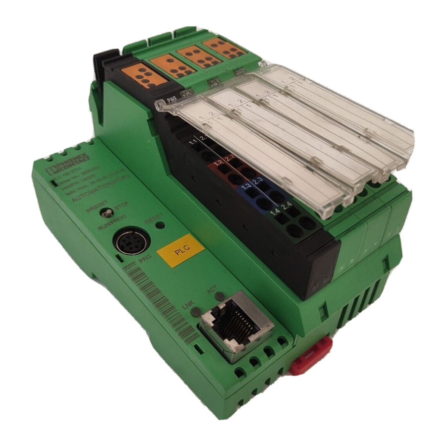
Components of the Inline controller

- Electronics base
- Reset button
- Programming interface
- Ethernet interface
- Power plug
- Plug for digital outputs
- Plug for digital inputs
- Diagnostic and status indicators
- End plate (snap onto the DIN rail as station end)
Structure of an Inline station

- End clamp (e.g., CLIPFIX 35-5, Order No. 3022276)
- Inline controller
- Terminals corresponding to application
- End plate
Mounting the electronics base

When snapping the Inline terminals onto the Inline controller, please observe the following:
Before snapping on the Inline controller, remove the terminal to be attached directly. It may only be attached after the Inline controller has been snapped in place.
Place the Inline controller onto the the rail (A) from above, then press it down (B).
Inserting the plugs

Insert the plugs in the specified order (A, B).
Removing a plug

Lift the plug by pressing on the back shaft latch (A) and removing it (B).
Removing the base

Before detaching, remove all plugs from the Inline controller.
If additional Inline terminals are snapped onto the Inline controller:
Remove the neighboring terminal before detaching the Inline controller. To do so, remove the plug of this terminal as well as the adjacent plug of the neighboring terminal on the right.
Insert a tool into the foot catch, pull the tool upwards (A) and pull the Inline controller from the rail (B, C).
Ethernet connection (10/100)
")
Connect the Ethernet network to the RJ45 socket.
Programming interface
(RS-232)

An IBM-compatible PC with the PC Worx / PC Worx Express software can be connected via the RS-232 serial interface.
You can order a suitable RS-232 cable with the designation PRG CAB MINI DIN (Order No. 2730611).
Connection assignment of the supply, actuators and sensors

| Power plug-in connector 1, PWR | |||
| 1.1 | U S | 2.1 | U M |
| 1.2 | U L | 2.2 | U M |
| 1.3 | GND UL | 2.3 | GND UM /US |
| 1.4 | FE | 2.4 | FE |
| Output plug 2, O1 | |||
| 1.1 | OUT1 | 2.1 | OUT2 |
| 1.2 | GND | 2.2 | GND |
| 1.3 | FE | 2.3 | FE |
| 1.4 | OUT3 | 2.4 | OUT4 |
| Input connector 3, I1 | |||
| 1.1 | IN1 | 2.1 | IN2 |
| 1.2 | U S | 2.2 | U S |
| 1.3 | GND | 2.3 | GND |
| 1.4 | IN3 | 2.4 | IN4 |
| Input connector 4, I2 | |||
| 3.1 | IN5 | 4.1 | IN6 |
| 3.2 | U S | 4.2 | U S |
| 3.3 | GND | 4.3 | GND |
| 3.4 | IN7 | 4.4 | IN8 |
Securing cables

Strip 8 mm off the cables.
Release the spring by pressing with the screwdriver (A).
Insert the cable into the terminal point (B).
Secure the cable by removing the screwdriver.
Display elements
| PLC | ||
| FR | green | Inline controller active |
| FF | yellow | Error |
| PWR | ||
| UL | green | 24 V communications power |
| US | green | 24 V segment voltage |
| UM | green | 24 V bus coupler and main voltage |
| IL | ||
| RDY | green | INTERBUS master ready to operate / data transmission active |
| FAIL | red | Error |
| BSA | yellow | Bus segment switched off |
| PF | yellow | Peripheral fault |
| OUT (O1) | ||
| E | red | Short circuit/overload at one or more outputs |
| Q1... Q4 | yellow | Status of the outputs |
| IN (I1-I2) | ||
| I1... I8 | yellow | Status of the inputs |
| ETH | ||
| LNK | green | Connection active |
| ACT | yellow | Data transmission active |


Documents / ResourcesDownload manual
Here you can download full pdf version of manual, it may contain additional safety instructions, warranty information, FCC rules, etc.
Download Phoenix Contact ILC 150 ETH - Industrial Electrical Equipment Installation Notes
Advertisement


Need help?
Do you have a question about the ILC 150 ETH and is the answer not in the manual?
Questions and answers