Table of Contents
Advertisement
Quick Links
Advertisement
Table of Contents

Related Manuals for ETS-Lindgren OMS


Summary of Contents for ETS-Lindgren OMS
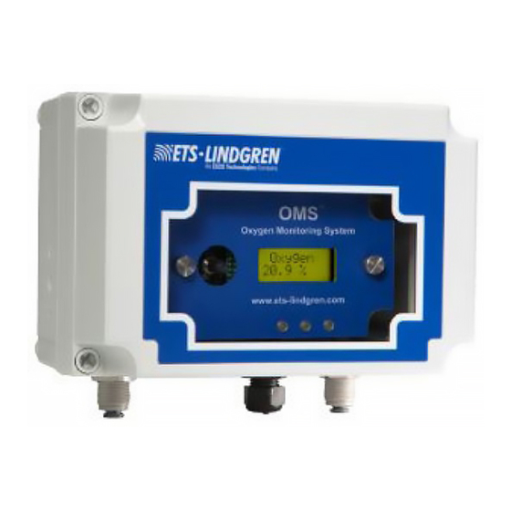
- Page 1 Sample Draw Oxygen Monitor System (OMS) User Manual May, 2020 399374 Rev D...
- Page 3 All trademarks are the property of their respective owners. © Copyright 2020 by ETS-Lindgren Inc. All Rights Reserved. No part of this document may be copied by any means without written permission from ETS-Lindgren Inc.
-
Page 5: Table Of Contents
Connect to 24 VDC Regulated Power ..... . 21 Connect OMS and Sensor Before Powering ....21 Do Not Exchange the Sensor Electronics . - Page 6 Mounting the OMS ........
- Page 7 Set Zero Suppression ........44 Set Alarm Threshold .
-
Page 8: Notes, Cautions And Warnings
Warning: Denotes a hazard. Failure to follow instructions could result in SEVERE personal injury and/or property damage. Included text gives proper procedures. See the ETS-Lindgren Product Information Bulletin for safety, regulatory, and other product marking information. Refer to Manual: When product is marked with this symbol, see the instruction manual for additional information. -
Page 9: Introduction
The OMS is suitable for indoor and outdoor use, and is intended to be installed outside of the shielded enclosure. -
Page 10: Other Optional Items
Optional Remote Display The remote display receives oxygen concentration information from the OMS. Up to two remote displays can be connected. See page 53 for installation information. Other Optional Items • Remote Horn and Strobe • Waveguide Installation Kit ETS-Lindgren Product Information Bulletin See the ETS-Lindgren Product Information Bulletin included with your shipment for the following: •... -
Page 11: Maintenance
Every 6-12 Months • Visual checks: Check for power and proper operation. The OMS should output a 17.34 mA signal when the oxygen level is at 20.9%. Also, the display should indicate 20.9% oxygen when the oxygen is at ambient levels. -
Page 12: Replacement And Optional Parts
Part Description Part Number Optional Remote Display 255552 Filter Replacement 255551 Service Procedures For the steps to return a system or system component to ETS-Lindgren for service, see the Product Information Bulletin included with your shipment. -
Page 13: Specifications
Loss of VDC power (analog signal drops to 0 mA) • Sensor cell failure: fault relay activated Humidity: 0% to 95% relative humidity (RH) Contact ETS-Lindgren for sensors which can operate in 100% condensing RH environments Gas Detection System Specifications Type: Long life zirconium oxide sensor cell, 0%–25%... -
Page 14: Signal Outputs
Set 4–20 mA loop The mA output is set at the factory using a calibrated Fluke meter. To set the OMS 4 mA (zero) and 20 mA (span) to your PLC or distributive control system. Set Formats; LED and Alarm Relay State... - Page 15 Menu Function / Description Factory Default Sensor Adjustment No factory default For use when dynamically gas calibrating the OMS to a known span gas; see page 46 for more information. Sensor Adjustment Factory default is 557 Manage Passwords To change the password from the factory...
-
Page 17: Component Views
Front cover—Removable, waterproof cover that protects the interior of the transmitter; fastened by four captive screws. Joystick—Used to select and adjust the built in menus. The OMS features dual level user selectable alarms. Digital display—Displays the oxygen levels in percentage; the normal oxygen level on Earth is 20.9%. -
Page 18: Front View, Cover Removed
Front View, Cover Removed Sample pump—Brings in a sample to the sensor. Flow rate is preset at the factory, and is continuously protected with a built in flow sensor. For more information, see Instrument Faults on page 32. Sensor assembly—A zirconium oxide sensor cell that detects and measures the level of oxygen. When exposed to oxygen, the sensor outputs an electrical signal proportional to the actual concentration of oxygen. -
Page 19: Transmitter Interior
Transmitter Interior The fuse is field-replaceable. The power analog output terminal block is a 5 pin terminal block where the 24 VDC power and 4–20 mA analog output connections are made Alarm Relay Board For the relays, from left to right: NC-C-NO... -
Page 21: Before You Begin Installation
The OMS must be installed outside of the shielded enclosure. The Sample Draw Oxygen Monitoring System (OMS™) enclosure should be mounted in an area free of vibration and electrical noise or interference. If possible, avoid areas with high temperatures or condensing humidity. -
Page 22: Do Not Exchange The Sensor Electronics
Keep Away from High Air Flow Do not expose the OMS to high air flow or install it directly in front of fans. High air flow can cool the sensor and cause inaccurate readings. -
Page 23: Installation
3.75 inches. The OMS should be mounted no closer than 12 inches above floor level. Airflow within the monitored area, the characteristics of the gas (lighter or heavier than air), and the position of workstations and personnel should all be... -
Page 24: Enclosure Mounting Feet
Enclosure Mounting Feet The four mounting feet can be oriented in any direction. The feet can also be removed for mounting the OMS flush with a wall or other surface. Dust Filter To protect the pump from dust, a particulate filter is provided. -
Page 25: Sample Draw Sensor Tubing
MRI room or shielded enclosure. The OMS flow pump continuously samples air drawn from end points up to a maximum of 100 feet (30 meters) from the unit. For optimal sensing, position the end point of the tube near the ceiling of the monitored space. A tuned pipe waveguide allows the tubing to enter the shield but attenuates electromagnetic interference (EMI) from entering. -
Page 26: Using Kit 55160 To Install Waveguide
Using Kit 55160 to Install Waveguide The Waveguide Kit 551060 includes the following: • 1/2-in threaded brass pipe waveguide (1 each) • 1/2-in brass bee nuts (2 each) To prevent linen dust or other airborne particulate matter from clogging the sensor tubing, use a small filtered terminus that can be serviced easily. -
Page 27: Wiring
0.62 miles (1 km). The OMS requires a single, 3 wire shielded cable for analog output and 24 VDC power input. The analog out and VDC power in connections are made on the terminal block inside the transmitter housing. -
Page 28: Connecting A Remote Horn And Strobe To Oms
Connecting a Remote Horn and Strobe to OMS The following illustrates how to connect a remote horn and strobe (federal signal horn/strobe, or equivalent) to the OMS with Alarm Relay #1 set to Normally Open. -
Page 29: Connecting A Remote Fan Contactor To Oms
Connecting a Remote Fan Contactor to OMS Use 24 VAC voltage inside the OMS; do not use 120 VAC or higher voltage,... -
Page 30: Initial Startup
Initial Startup Once installation of the OMS is complete, it is ready for startup. Follow these steps prior to putting the OMS into operation: Check the integrity of all wiring. Apply 24 VDC power to the power supply PCB board. The sample pump will activate and the digital display second line will quickly display the digital transmitter module (DTM), serial number, and software version. -
Page 31: Operation
The joystick has a built in delay to prevent accidental tampering with the menus; deliberate entries are required. The Sample Draw Oxygen Monitoring System (OMS™) uses an 8 position joystick with a center pushbutton for selecting menus and changing values. The joystick is programmed to standard protocol as follows: + Plus Push the joystick in this direction to increase the value. -
Page 32: Internal Sample Flow Rate
Internal Sample Flow Rate The OMS has an internal sample pump flow rate that is programmed at the factory and cannot be changed in the field. A flow sensor on the relay board continually monitors flow rate and when a loss of flow is detected, a signal is sent to the fault relay and the front mounted LED will activate. -
Page 33: Loss Of Power Indicator
Loss of Power Indicator If the OMS loses 24 VDC power, the 4–20 mA analog output signal drops to 0 mA. The display will show a blank screen. Alarm Reset If the OMS is supplied with the optional alarm relays, when the monitors alarms are activated, the built in alarm relays, panel mounted LEDs, and optional audio horn will also activate. -
Page 35: Programming The Oms
Only qualified personnel should program the OMS. The Sample Draw Oxygen Monitoring System (OMS™) is supplied with user selectable settings to adjust the alarm settings, 4 and 20 mA output, and minor sensor adjustments. The settings are arranged in menus that are accessed by moving the joystick. -
Page 39: Passwords
(DTM) for the OMS, which is displayed by moving the joystick to the left. Enter Password The OMS has a factory set password to prevent unauthorized access to the menus; the password is 557. Following are the steps to enter the password:... -
Page 40: Change Password
Failed. Push the joystick to the left to access the monitoring mode. From this mode you can re enter the password. Change Password The OMS has a factory set password to prevent unauthorized access to the menus; the password is 557. Following are the steps to change the password: Step Display 1. -
Page 41: Enable/Disable Password Function
Set 4–20 mA Loop This set of menus is used to adjust the 4 mA and 20 mA output from the OMS. It also provides a function to send an actual output between 4 mA and 20 mA to test any remote control and alarm system attached to the OMS. -
Page 42: Set Formats
This set of menus is used to adjust the relay states for the two gas alarm relays and the individual instrument fault relay. To access this menu, the OMS must be installed with the relay module. If not installed, the display will indicate N/A (not available). -
Page 43: Set Latching
In a non latching state, the alarm relay will automatically reset once the gas concentration has returned to 20.9% for oxygen. To access this menu, the OMS must be installed with the relay module. If not installed, the display will indicate N/A (not available). -
Page 44: Reset Latching Alarm
Any system fault will immediately activate the fault relay. Set Zero Suppression Although these settings can be changed, this function is disabled on the OMS; it is only used to decrease the sensitivity of selected gas sensors. The factory default is set at 000. -
Page 45: Set Alarm Threshold
Set Alarm Threshold To access this menu, the OMS must be installed with the audio alarm option module. Step Display 1. Push the joystick to the right to select the first Set Relay 1 Alarm Threshold submenu. 2. This is the gas concentration at which the first level The display will indicate a value alarm will be activated. -
Page 46: Set Alarm Hysteresis
Set Alarm Hysteresis The OMS may be used as a control system. When used to regulate oxygen levels, a dead band, hysteresis may be required. This menu sets the alarm hysteresis to a desired concentration of oxygen. When using hysteresis, the alarm set point becomes an average alarm setting for an action to occur. - Page 47 4. Push the joystick to the left to go back to the main Sensor Adjustment menu. Set Module Zero is not available for the OMS; it was designed for toxic and corrosive gas monitors. Push the joystick to the left to exit this menu.
-
Page 49: Sensor Verification
Draw Oxygen Monitoring System (OMS™) to 20.9% oxygen is constantly being performed. As the sensor ages over time, it may require a slight adjustment to 20.9%. The OMS also requires periodic testing with nitrogen to verify the cells response to 0% oxygen. -
Page 50: Sensor Verification Procedure
The filter on the OMS has a 1/4 in male tube fitting designed to connect sample tubing from a nitrogen cylinder. Expose the OMS to nitrogen using the on demand regulator. The reading will drop off to 1% or below in less than one minute when the sensor is exposed to pure nitrogen. -
Page 51: Sensor Verification To Known Concentration Of Oxygen
The sensor inlet on the OMS has a 1/4 in compression tube fitting designed to connect to the filter. Connect 1/4 in diameter sample tubing from a nitrogen cylinder directly to the filter. Expose the OMS directly from the nitrogen cylinder and the reading will drop off to the span gas concentration in less than one minute. -
Page 53: Remote Display Alarm Indicator
REMOTE DISPLAY ALARM INDICATOR The Remote Display Alarm Indicator is designed to display remote oxygen concentration information from the oxygen monitor. The O2 monitor has a built in 4-20mA output. The remote display alarm easily connects to the monitor’s input power and mA output connection. -
Page 54: How To Wire The Remote Display Alarm Indicator
Mount the case to a wall or other flat surface. There are 4ea. through holes for fastening the case. The case is designed to be flush mounted. The front cover can be removed from the case by gently pulling on the plastic hinges. -
Page 55: Identification Of Switches And Controls
Identification of Switches and Controls Alarm Adjusting Switches – These switches are used select the alarm level to be adjusted. They are factory set at 19.5% for Alarm 1 and 18% for Alarm 2. (Normally set at the factory) Alarm Polarity Switches – These switches are used to select when the alarms will activate. For oxygen the alarm switches are set for “Below”. -
Page 56: How To Set Up And Operate The Remote Display
How to Set up and Operate the Remote Display Entering the setup menus will disable the real time oxygen readings. After wiring the remote display to your Oxygen monitor, turn on the power to your oxygen monitor. During the warm up the remote display will illuminate a yellow fault LED and the display will read FLt, (indicating that the oxygen monitor is in fault). -
Page 57: How To Set The Internal Alarms On The Remote Display
How to Set the Internal Alarms on the Remote Display The Remote Display has two user selectable alarms with a separate horn tone to identify Alarm 1 from Alarm 2. Both are preset at the factory; AL1 = 19.5% and AL2 = 18%. They can be changed in the field. To set Alarm 1, Press Alarm 1 for two seconds to enter the alarm change mode. -
Page 59: Appendix A: Warranty
APPENDIX A: WARRANTY See the Product Information Bulletin included with your shipment for the complete ETS-Lindgren warranty for your Oxygen Monitoring System. Duration of Warranties for Oxygen Monitoring System All product warranties, except the warranty of life, and all remedies for warranty failures are limited to one year.
Need help?
Do you have a question about the OMS and is the answer not in the manual?
Questions and answers