
Related Manuals for ETS-Lindgren HI-6100


Summary of Contents for ETS-Lindgren HI-6100
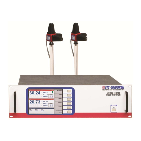
- Page 1 HI-6100 Field Monitor User Manual HI-6100 Field Monitor shown with optional probes...
- Page 2 ETS-Lindgren, Inc. Trademarks used in this document: The ETS-Lindgren logo is a trademark of ETS-Lindgren, Inc. Revision Record | MANUAL,HI-6100 | Part #H-600099, Rev. F Revision Description Date...
-
Page 3: Table Of Contents
Battery Probe Set Up ................19 Laser Probe Setup ................20 Remote Connections ................... 21 Mounting the HI-6100 in a Rack ..............21 Mounting Data Modules ................22 5.0 Operation ................25 Back Panel ....................25 ... - Page 4 Probe Menu ..................30 —Temperature Units ..............30 —MinMax Reset ................31 —Range ..................32 —Axis Enable ................32 Display Menu ..................33 —Channel Enable ............... 33 —Probe Parameter ..............35 —Lower Display ................
- Page 5 —Read Battery Voltages ............. 51 —Read Peak ................51 —Reset Peak ................51 —Read Temperatures ..............52 —Setup Recall ................52 —Setup Save ................53 —Software Revision ..............53 —Verbose Mode ................54 ...
-
Page 6: Table Of Figures
Laser Data Module ............. 23 Figure 5: HI-6100 Back Panel ............25 Figure 6: HI-6100 Front Panel (shown with optional case) ....26 Figure 7: Overview of HI-6100 Menu Options ......... 27 Figure 8: Previous Option On Each Menu ......... -
Page 7: Notes, Cautions And Warnings
Notes, Cautions and Warnings Note: Denotes helpful information intended to provide tips for better use of the product. Caution: Denotes a hazard. Failure to follow instructions could result in minor personal injury and/or property damage. Included text gives proper procedures. Warning: Denotes a hazard. -
Page 8: General Safety Considerations
General Safety Considerations Caution: Uninsulated voltage within the unit may have sufficient magnitude to cause electric shock. Therefore, it is dangerous to make any kind of contact with any parts inside this unit. Warning: This is a Safety Class I product (provided with a protective earthing ground incorporated in the power cord). -
Page 9: Introduction
The safety mechanism is intended to prevent injury from the laser if the HI-6100 issues a command to turn on the laser while the fiber optic cables are disconnected, improperly connected, cut, or damaged. -
Page 10: Standard Configuration
ETS-Lindgren may substitute a similar part or new part number with the same functionality for another part/part number. Contact ETS-Lindgren for questions about part numbers and ordering parts. Part Description Part Number HI-6100 Field Monitor HI-6100 Shipping End Caps H-390076 Power Cord... -
Page 11: Ets-Lindgren Product Information Bulletin
Part Description Part Number Fiber Optic Cable (SMA) H-491106-XX Fiber Optic Cable (FC/ST) H-491263-XX Cleaning Kit H-34F01 ETS-Lindgren Product Information Bulletin See the ETS-Lindgren Product Information Bulletin included with your shipment for the following: Warranty information Safety, regulatory, and other product marking information ... - Page 12 This page intentionally left blank. Introduction...
-
Page 13: Maintenance
ETS-Lindgren Customer Service. Annual Calibration Probes used with the HI-6100 Field Monitor require annual calibration to verify that they are performing within specifications. See the Product Information Bulletin included with your shipment for information on ETS-Lindgren calibration services. -
Page 14: Laser Probes And Maintenance Of Fiber Optics
Laser Probes and Maintenance of Fiber Optics The fiber optic connectors and cables used with laser-powered probes can be damaged from airborne particles, humidity and moisture, oils from the human body, and debris from the connectors they plug into. Always handle connectors and cables with care, using the following guidelines. -
Page 15: Handling Instructions
Use the cleaning tape shipped with the HI-6105 kit for cleaning the end face of the connector. Softly press the connector face on the exposed cleaning tape and move in a figure eight motion. After three figure eights inspect with a microscope and repeat if necessary. ... - Page 16 This page intentionally left blank. Maintenance...
-
Page 17: Specifications
3.0 Specifications Electrical Specifications Nominal AC Voltage: 115/230 V Input Frequency: 50/60 Hz Maximum Output Power: 250 W Physical Specifications Outer Dimensions: Length: 48.3 cm (19 in) Width: 35.6 cm (14 in) Height: 13.3 cm (5.25 in) Approximate Weight: 5.9 kg (13 lb) Approximate Weight, including 11.8 kg (26 lb) Optional Bench Top Case:... - Page 18 This page intentionally left blank. Specifications...
-
Page 19: Assembly And Installation
4.0 Assembly and Installation Before connecting or operating any components, follow the safety information in the ETS-Lindgren Product Information Bulletin included with your shipment. Prior to assembly and installation, see Cleaning Instructions on page 14 and Handling Instructions on page 15. Set Up Procedure Perform the following procedures to verify system operation before installation in the test environment. -
Page 20: Laser Probe Setup
Connect the AC power cord to the IEC connector on the back of the HI-6100 Field Monitor. Verify the power supply switch is in the ON position. Plug the other end of the power cord into an electrical outlet. Turn on the battery powered probe(s). -
Page 21: Remote Connections
(outside of the rack) must be less than the maximum operating temperature of the HI-6100 by 4°C for every 100 Watts dissipated in the rack. If the total power dissipated in the cabinet is greater than 800 Watts, then forced convection must be used. -
Page 22: Mounting Data Modules
Mounting Data Modules Optical data modules or laser data modules may be mounted on any available channel. Figure 2: HI-6100 Module Locations Figure 3: Optical Data Module Assembly and Installation... -
Page 23: Figure 4: Laser Data Module
Figure 4: Laser Data Module Remove the cover by removing the two screws on the back panel and the nut on the laser data module angle bracket, if installed. Place the new module in the desired channel location and secure with two screws on the back panel and the nut on a laser data module angle bracket, if available. - Page 24 This page intentionally left blank. Assembly and Installation...
-
Page 25: Operation
Back Panel Do not block the power supply fan. It must remain unobstructed at all times. Figure 5: HI-6100 Back Panel The back panel of the HI-6100 Field Monitor includes: Dedicated connection ports—IEEE-488 GPIB, RS-232, and Update. Device label locations—Place the warning label shipped with each probe in these marked locations. -
Page 26: Front Panel
Power button—Includes an indicator light allowing the user to easily verify if the unit is on or off. To turn off the HI-6100, press and hold the power button for three to four seconds. HI-6100 Menu Options On the page 27 is an illustration of the HI-6100 menu hierarchy. The illustration serves as an overview or map of the menu options;... -
Page 27: Overview Of Hi-6100 Menu Options
Overview of HI-6100 Menu Options Figure 7: Overview of HI-6100 Menu Options Operation... -
Page 28: Hi-6100 Display
HI-6100 Display REVIOUS PTION Select Previous at the top of each menu series to return to the previous screen and, eventually, to the main menu. Figure 8: Previous Option On Each Menu Operation... -
Page 29: Find Probes Menu
ROBES The HI-6100 display simultaneously exhibits up to four probes. Select Find Probes to automatically display the number of probes that are enabled. The system will search each channel, determine which of the enabled channels are active, and then display those channels. -
Page 30: Probe Menu
ROBE Selecting Probe provides several choices that relate directly to the information available for the probe(s) in use. Figure 10: Probe Menu —Temperature Units Select Temperature Units to toggle between Fahrenheit and Celsius temperature readings. Figure 11: Probe Menu—Temperature Units Selection Operation... -
Page 31: Minmax Reset
—MinMax Reset Select Min/Max Reset to reset the individual probe values. Please note that the min/max values may not be visible. Figure 12: Probe Menu—Min/Max Reset The Range and Axis Enable options under the Probe menu will only appear when the mode is set to FM5004 under the Systems menu. Operation... -
Page 32: Range
—Range Select Range to manually set the range. The HI-6XXX probe range is not adjustable; these are single range probes. Figure 13: Probe Menu—Range —Axis Enable Use Axis Enable to select the channel or probe to be adjusted and the axis to be enabled or disabled. -
Page 33: Display Menu
ISPLAY Select Display from the main menu to customize the display. Figure 15: Display Menu —Channel Enable Choose Channel Enable from the display menu to manually select the channel(s) to view on the display. Up to four channels may be viewed on one screen. -
Page 34: Figure 17: Channel Enable Selected-Three Channel Displays
Once Channel Enable is selected, the user may distinguish which channels are currently on/off by selecting the screen where each channel and their status are noted. In addition, the user has the option to turn on/off a channel by pressing that channel button. -
Page 35: Probe Parameter
—Probe Parameter When selecting Probe Parameter, the lower right corner of the active channel screen(s) will toggle between parameters, min/max/avg, and laser warning views. When the program is closed, upon re-starting the system the display automatically appear as it was last configured. Figure 18: Display Menu—Probe Parameter Operation... -
Page 36: Lower Display
—Lower Display Lower Display corresponds to the window shaded gray at the bottom of the display. By pressing the button for this option, the system will toggle between the probe, min/max/avg for all active probes, controller error, and probe error information. When the controller and probe error readouts are selected, the last six errors the system experienced will be visible. -
Page 37: Color
—Color Select Color to scroll through several pre-determined color schemes. These color schemes are designed to allow optimal display of the monitor information accommodating unique user environments. Figure 20: Display Menu—Color Operation... -
Page 38: Remote Menu
EMOTE Select Remote to set the communication parameters. Figure 21: Remote Menu —GPIB Address By selecting GPIB Address in the Remote menu, the address will scroll between 31 available addresses. Figure 22: Remote Menu—GPIB Address Operation... -
Page 39: Rs-232 Baud
—RS-232 Baud Select RS-232 Baud to set the baud rate for the external serial ports. Figure 23: Remote Menu—RS-232 Baud Operation... -
Page 40: System Menu
YSTEM Select System to access systems settings. Figure 24: System Menu —Set Time Select Set Time to set the time. Figure 25: System Menu—Set Time Operation... -
Page 41: Reset
—Reset Select Reset to return the HI-6100 to the factory default configuration. Figure 26: System Menu—Reset —More Select More to display a list of additional system selections. Figure 27: System Menu—More Operation... -
Page 42: Software
—Software For informational purposes only. The button has no effect. Figure 28: System, More Menu—Software Operation... -
Page 43: Mode
HI-6000, and HI-4400 series of probes. See Appendix D on page 65 for a list of supported FM5004 commands. In the HI-6100 mode only the HI-6000 series probes are supported and a new GPIB command set is utilized. See Appendix C on page 63 for HI-6100 commands. -
Page 44: Update Software
Go to www.ets-lindgren.com. On the Resources menu, click Software/Firmware. Find the HI-6100 upgrade file in the Software column and follow the on-screen instructions to download. Follow the instructions included with the file to install the updated software. -
Page 45: Gpib Output Mode
—GPIB Output Mode Allows the user to configure the HI-6100 to format the output data while in FM5004 mode. The 4-Lines setting requires four consecutive reads (ibrd). The 1-Line setting requires a single read. This setting has no effect when the HI-6100 mode is selected. -
Page 46: Gpib Status Menu
GPIB S TATUS GPIB Status allows the user to return the HI-6100 to local mode. This enables all other menu functions. Figure 32: GPIB Status Select Remote/Local to toggle between the two selections. Figure 33: System, GPIB Status Menu—Remote/Local Operation... -
Page 47: Remote Operation
ETS-Lindgren Product Information Bulletin included with your shipment. This chapter describes remote operation of the HI-6100 Field Monitor using either the IEEE-488 parallel port or the RS-232 serial port connected to a remote device, such as an IEEE-488 bus or a personal computer. -
Page 48: Ieee-488 (Gpib) Communications
IEEE-488 (GPIB) Communications For General Purpose Interface Bus (GPIB) communications, the End or Identify (EOI) control line may also be used for command termination. Terminate the command with <LF>, EOI, or both when sending commands to the receiver via the GPIB. No characters are permitted after <LF> or EOI; the system interprets characters following <LF>... -
Page 49: Figure 35: Hi-6100 Pin # Designations Table
Ready to Send Clear to Send No Connection Figure 35: HI-6100 Pin # Designations Table A null modem cable or adapter (supplied by the user) is required for interfacing the HI-6100 to a standard serial port on a computer. Remote Operation... -
Page 50: Remote Commands
Remote Commands The commands described in the following pages are available to the user for remote communications with the HI-6100. The following conventions are used: A lower case x in the command or returned data syntax represents a numeric value. -
Page 51: Read Battery Voltages
—Read Battery Voltages Returns the current battery percentages of probes in use. Syntax: RBAT? Parameters: None To check the current battery percent of the probes in use: RBAT?<LF> Response: 62%,100%,,<CR><LF> Channels 3 and 4 are not on or not ready. —Read Peak Writes the peak probe field values to a remote port. -
Page 52: Read Temperatures
To check the current temperature of the probes in use: RTMP?<LF> Response: 77F,100F,,<CR><LF> Channels 3 and 4 are not on or not ready. —Setup Recall Recalls a saved HI-6100 setup. Syntax: RECL,x Parameters: (x) 1 = Recall setup #1 3 = Recall setup #3... -
Page 53: Setup Save
The setup will be saved to memory and can be recalled with the command RECL,1. —Software Revision Returns the current revision of the HI-6100 operating software. Syntax: SREV Parameters: None To check the current revision of the HI-6100 software: SREV?<LF> Response: SREV,1.0<CR><LF> Remote Operation... -
Page 54: Verbose Mode
—Verbose Mode Sets the HI-6100 to respond to all remote commands or to respond to inquiries only. Syntax: VERB,x Parameters: (x) 0 = Verbose mode disabled 1 = Verbose mode on Examples To enter verbose mode: VERB,1<LF> Response: -VERB,1<CR><LF>... -
Page 55: Channel Enable
4 = Channel 4 To enable channel 1: CHAN,1,1<LF> —Local Mode Returns the HI-6100 to local mode when it is in remote mode. Local mode allows the operator to use the front panel buttons. Syntax: LOCL,x Parameters: Local mode enable (x) - Page 56 This page intentionally left blank. Remote Operation...
-
Page 57: Error Handling And Troubleshooting
Troubleshooting Following are some common troubleshooting tips for the HI-6100 Field Monitor. If you have a problem not listed or if the corrective action fails, contact ETS-Lindgren Customer Service. - Page 58 This page intentionally left blank. Error Handling and Troubleshooting...
-
Page 59: Appendix A: Warranty
Appendix A: Warranty See the Product Information Bulletin included with your shipment for the complete ETS-Lindgren warranty for your HI-6100. HI-6100 URATION OF ARRANTIES FOR THE All product warranties, except the warranty of title, and all remedies for warranty failures are limited to three years. - Page 60 This page intentionally left blank. Warranty...
-
Page 61: Appendix B: Ec Declaration Of Conformity
Appendix B: EC Declaration of Conformity EC Declaration of Conformity... - Page 62 This page intentionally left blank. EC Declaration of Conformity...
-
Page 63: Appendix C: Commands
Appendix C: Commands For a list of FM5004 compatibility commands, see Appendix D: Commands in FM5004 Mode on page 65. IEEE 488.2 Commands Command Description *CLS Clear status *ESE Event status enable *ESR Event status register *IDN Identification query *OPC Operation complete query *RST Reset... - Page 64 Command Description SREV Software revision RDPK Read min/max peak RSPK Reset min/max peak VERB Verbose mode Commands...
-
Page 65: Appendix D: Commands In Fm5004 Mode
Appendix D: Commands in FM5004 Mode Unsupported Commands in FM5004 Mode The following commands are not supported in either the HI-6100 mode or the FM5004 mode. In general, the HI-6100 Field Monitor does not have alarm or analog output capabilities. Functions to adjust the LCD and the display have also been removed. -
Page 66: Analog Output Functions
UNCTIONS Analog output functions are not available on the HI-6100. These commands are included for test software compatibility purposes only and have no effect on the HI-6100. An error entry will be added to the CONTROLLER COMMUNICATIONS error list. Command... -
Page 67: Fm5004 Commands
Command Response Sample Rate SMPR,00<CR><LF> The sample rate is probe-dependent and set run as fast as possible. System Alarm, — Hard Probe Failure System Alarm, — Momentary Probe Failure Display Update Rate DUPR,5<CR><LF> The display update rate is fixed at 7 samples/second. -
Page 68: Supported Commands
Command Description *TRG Trigger *TST Self-test query *WAI Wait to continue UPPORTED OMMANDS Command Description BAUD Baud rate entry CHRA Change probe range CLED Channel LEDS DSFM Display format GPIB GPIB address LERR Last errors LOCL Local RBAT Read battery voltage RDIS Read display RECL... -
Page 69: Unsupported Commands
NSUPPORTED OMMANDS Command Description ADFM Alt Display Format ALAT Alarm Latch ALOV Alarm Lower Value ALOE Alarm Lower Enable ALSR Alarm Silence ANAO Analog out ANAR Analog Range AUPE Alarm Upper Enable AUPV Alarm Upper Value BUSV Buss Voltage CLCK Key Click DATE Software Date... - Page 70 This page intentionally left blank. Commands in FM5004 Mode...
-
Page 71: Appendix E: Gpib Register
Appendix E: GPIB Register Figure 36: GPIB Registers GPIB Register...
Need help?
Do you have a question about the HI-6100 and is the answer not in the manual?
Questions and answers