Table of Contents
Advertisement
Quick Links
Advertisement
Table of Contents

Related Manuals for ETS-Lindgren HI-3604


Summary of Contents for ETS-Lindgren HI-3604
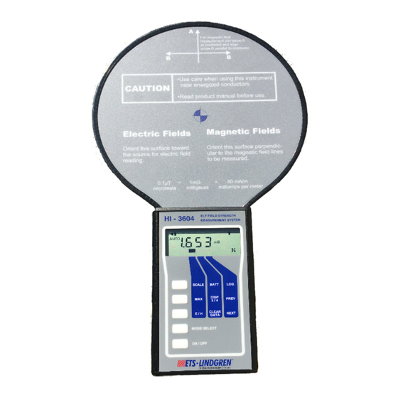
- Page 1 Model HI-3604 Survey Meter User Manual...
- Page 2 ETS-Lindgren, Inc. reserves the right to make changes to any product described herein in order to improve function, design, or for any other reason. Nothing contained herein shall constitute ETS-Lindgren, Inc. assuming any liability whatsoever arising out of the application or use of any product or circuit described herein. ETS-Lindgren, Inc. does not convey any license under its patent rights or the rights of others.
-
Page 3: Table Of Contents
Safety Information ..............v 1.0 Introduction ................7 Standard Configuration ................11 ETS-Lindgren Product Information Bulletin ..........11 2.0 Maintenance ............... 13 Maintenance Recommendations ..............13 Replacement and Optional Parts ..............14 ... - Page 4 Using the HI-3616 Fiber Optic Remote Control ........... 39 Using the HI-3616 ................39 Using the Recorder Output ..............40 Appendix A: Warranty ............. 42 Appendix B: EC Declaration of Conformity ......44 www.ets-lindgren.com...
-
Page 5: Notes, Cautions, And Warnings
SEVERE personal injury and/or property damage. Included text gives proper procedures. Note: See the ETS-Lindgren Product Information Bulletin for safety, regulatory, and other product marking information Safety Information Refer to Manual: When product is marked with this symbol, see the instruction manual for additional information. - Page 6 At end of useful life, please recycle the used batteries, or dispose of them safely and properly. Many cities collect used batteries for recycling or disposal. You may contact your local waste disposal agency for information on battery recycling and disposal. www.ets-lindgren.com...
-
Page 7: Introduction
The HI-3604 has two selectable sensors for measuring both electric and magnetic fields. The instruments' capabilities include data-logging, waveform output, full auto-ranging, and a custom Liquid Crystal Display (LCD) with a bar graph. - Page 8 This feature permits the HI-3604 to be used in environments having significant harmonic content and yield accurate measures of the resultant fields.
- Page 9 The HI-3604 can be user programmed to indicate in either units of milligauss/gauss, milliamperes/amperes per meter, or nano/micro teslas. The HI-3604 indicates magnetic field flux density in units of milligauss (mG) and gauss (G). The SI unit of magnetic field flux density is the tesla (T).
- Page 10 Figure 1-1: Magnetic Field Response Figure 1-2: Electric Field Response This signal is available from the phone jack located at the bottom of the instrument. Connection of an oscilloscope to this jack will allow observation of the preamplifier output. www.ets-lindgren.com...
-
Page 11: Standard Configuration
Manual A list of optional items is included in “Replacement and Optional Parts” on page 14. ETS-Lindgren Product Information Bulletin See the ETS-Lindgren Product Information Bulletin included with your shipment for the following: Warranty information Safety, regulatory, and other product marking information ... - Page 12 This page intentionally left blank. www.ets-lindgren.com...
-
Page 13: Maintenance
Before performing any maintenance, follow the safety information in the ETS-Lindgren Product Information Bulletin included with your shipment. Maintenance of the HI-3604 is limited to external components such as cables or connectors. Warranty may be void if the housing WARRANTY is opened. -
Page 14: Replacement And Optional Parts
Replace the screws and tighten into place. Replacement and Optional Parts ETS-Lindgren may substitute a similar part or new part number with the same functionality for another part/part number. Contact ETS-Lindgren for questions about part numbers and ordering parts. -
Page 15: Service Procedures
Service Procedures ETS-L ONTACTING INDGREN Note: Please see www.ets-lindgren.com for a list of ETS-Lindgren offices, including phone and email contact information. ENDING A OMPONENT FOR ERVICE For the steps to return a system or system component to ETS- Lindgren for service, see the Product Information Bulletin included with your shipment. - Page 16 This page intentionally left blank. www.ets-lindgren.com...
-
Page 17: Specifications
+0.5, -2.5 dB (30-2000 Hz) Dynamic Range Electric: 1 V/m – 200 kV/m Magnetic: 0.2 mG – 20 G Response True RMS Logging On-Board, 112 Readings (max) Sensitivity Electric fields – 1 V/m-199 kV/m Magnetic field – 0.1 mG-20 G www.ets-lindgren.com... -
Page 18: Physical Specifications
Switch selectable between electric and magnetic fields. Output Liquid crystal display; preamplifier output via phono jack (analog signal from sensor/preamplifier equal to 1 mV/(mA/m); digital fiber optic signal (for remote reading via connection to HI-3616 Fiber Optic Remote Control). www.ets-lindgren.com... -
Page 19: Example Applications
Power Frequency Fields The HI-3604 finds application in numerous circumstances involving 60-Hz fields. A prime example of the HI-3604's utility is evaluation of electric and magnetic fields in the vicinity of electric power lines. In this case, the electromagnetic field environment surrounding a typical power transmission line can be visualized through Figure 4-1. - Page 20 Figure 4-1: Single-circuit, three phase power line consisting of three separate electrical conductors www.ets-lindgren.com...
- Page 21 Figure 4-2 represents the magnetic fields if the line was carrying a current of 1000 A and indicates a maximum value of 175 mG (equivalent to 14 A/m). www.ets-lindgren.com...
- Page 22 Figure 4-2: Spatial Distribution of Field Strength www.ets-lindgren.com...
-
Page 23: Field Strength Measurements
In either case, with the instrument elevated on a tripod or laying on the ground, the HI-3604 should be oriented so that the long axis of the body of the instrument is parallel to the conductors of the power line. - Page 24 Figure 4-3: Orientation of HI-3604 for Measurement of Vertical Electric Field Strength Beneath a Power Line www.ets-lindgren.com...
- Page 25 While performing magnetic field measurements, the HI-3604 may be held by the operator. The non-magnetic nature of the human body does not perturb the magnetic field nor interfere with the operation of the sensor.
-
Page 26: Waveform Measurements
Waveform Measurements A useful feature of the HI-3604 is the ability to display waveform information about electric or magnetic fields being sensed. The waveform display output is a 1/8 inch phone jack located on the bottom of the instrument case. Using this output, the waveforms of the incident fields maybe monitored by connection to an oscilloscope. - Page 27 VDT consist of many horizontal sweeps of an electron beam across the screen to trace out the intended image; when the electron beam reaches the bottom of the screen, it is returned rapidly to the top of the screen from where it again repeats www.ets-lindgren.com...
- Page 28 The peak-to-peak output (in millivolts) from the waveform jack is nominally related to the observed field as follows: Figure 4-7: Waveform of Magnetic Field produced by the vertical deflection circuit in a VDT Refer to Section 6, Using the Recorder Output for more information. www.ets-lindgren.com...
-
Page 29: Frequency Measurements
Gauss Range 100 mV/Gauss Frequency Measurements Connection of a frequency counter to the waveform output jack allows immediate measurement of the frequency of the applied magnetic field. To perform this measurement, a portable digital multimeter (DVM) capable of measuring www.ets-lindgren.com... - Page 30 HI-3604 to, for example, determine the vertical refresh rate on a VDT. To perform this measurement, an analog signal sufficient to drive some frequency counters may require that the HI-3604 be placed in fairly strong field...
-
Page 31: Before You Begin
HI-3604 to avoid damaging the sensor by striking it against objects or applying excessive force to the sensor paddle. When not in use, keep the HI-3604 in its protective case where the sensor paddle is properly supported. Do not use hard or pointed objects to operate the switch keypads. - Page 32 This page intentionally left blank. www.ets-lindgren.com...
-
Page 33: Operation
ETS-Lindgren Product Information Bulletin included with your shipment. Keypad Matrix Membrane switches are used for controlling the HI-3604’s operation. The switch keypads are activated by gently pressing on the center of the pad with a fingertip. www.ets-lindgren.com... -
Page 34: Using The Hi-3604
Using the HI-3604 IGITAL ISPLAY The HI-3604 uses a custom LCD to provide information on instrument settings as well as the variables being measured. When the meter is turned on, a self-test procedure is automatically performed. As part of this procedure, all segments of the display are lit for about two seconds. -
Page 35: Battery Condition
The HI-3604 does not include an automatic turn off. Turn the instrument off when not in use or between readings. Zero—A zero function is not required or provided on the HI-3604. The instrument will immediately show the measured field strength. -
Page 36: Keypad Matrix
EYPAD ATRIX For maximum flexibility in operation, the HI-3604 has a keyboard matrix for the upper three keypads on the membrane switch panel. The function of each of the three keys can be changed depending on the location of the cursor block in the LCD. The cursor block is a dark rectangle located at the bottom edge of the LCD. -
Page 37: Mode Select
CALE The SCALE keypad changes the fixed ranges or scales of the instrument. When turned on, the HI-3604 is in the AUTO RANGE mode. The unit determines the correct range within the current mode (E or H field) according to the detected field level. As the field being measured increases or decreases, the range is automatically selected for best resolution and accuracy. -
Page 38: Max
LCD. On releasing the MAX keypad, the reading is held for about two seconds and then the memory is cleared and a new maximum reading accumulated. When the instrument is shifted between the electric and the magnetic field mode, the MAX reading memory is cleared. www.ets-lindgren.com... -
Page 39: Using The Hi-3616 Fiber Optic Remote Control
HI-3616 Fiber Optic Remote Control. The HI-3604 is normally in a "listening" mode. It is continually looking for a signal or command from the HI-3616. In this manner, it is saving power by not having to use its fiber optic transmitter unless actually communicating with the HI-3616. -
Page 40: Using The Recorder Output
It is a 0-4 VDC signal with the four volt level representing a "full scale" indication. The field value represented by the output signal depends on the setting of the range switch. The output drives a load of 5,000 ohms or more. www.ets-lindgren.com... - Page 41 This page intentionally left blank. www.ets-lindgren.com Operation...
-
Page 42: Appendix A: Warranty
Appendix A: Warranty See the Product Information Bulletin included with your shipment for the complete ETS-Lindgren warranty for your HI-3604. HI-3604 S URATION OF ARRANTIES FOR URVEY ETER All product warranties, except the warranty of title, and all remedies for warranty failures are limited to one year. - Page 43 This page intentionally left blank. www.ets-lindgren.com Warranty...
-
Page 44: Appendix B: Ec Declaration Of Conformity
Appendix B: EC Declaration of Conformity The EC Declaration of Conformity is the method by which ETS-Lindgren Inc. declares that the equipment listed on this document complies with the EMC Directive and Low Voltage Directive. Factory Issued by ETS-Lindgren Inc. - Page 45 The authorizing signatures on the EC Declaration of Conformity document authorize ETS-Lindgren Inc. to affix the CE mark to the indicated product. CE marks placed on these products will be distinct and visible. Other marks or inscriptions liable to be confused with the CE mark will not be affixed to these products.
Need help?
Do you have a question about the HI-3604 and is the answer not in the manual?
Questions and answers