Table of Contents
Advertisement
Quick Links
Advertisement
Table of Contents

Related Manuals for NewLine HO Series


Summary of Contents for NewLine HO Series
- Page 1 Collaboration Touch Screen HO Series Quick Start Guide V1.0...
- Page 2 Thank you for choosing Newline collaboration touch screen. The symbol of the crossed out wheeled bin indicates this product should not be placed in municipal waste. Instead, dispose of waste equipment by handing it over to a designated collection point for the recycling of electrical and electronic equipment.
- Page 3 Symbol Convention Symbols are used in this document to indicate operations that require special attention. The symbols are defined as follows: Indicates a hazard with risk that, if not avoided, could result in death or injury. WARNING Indicates a potentially hazardous situation that, if not avoided, could result in equipment damage, data loss, performance deterioration, or unanticipated results.
-
Page 4: Safety Instructions
Safety Instructions For your safety, please read the following instructions before you use the product. Improper operations may cause severe injury or property damage. Please refrain from repairing the product on your own. WARNING If major failures occur, disconnect the product from power source immediately. Major failures include the following: Smoke, peculiar smell or abnormal sound discharged from the product. - Page 5 WARNING Do not place items on top of the product. Do not put items, such as a liquid container (a vase, flowerpot, cosmetics or liquid medicine) on the top of the product. If any water or liquid is spilled on the product, a short circuit may occur and cause fire or ...
- Page 6 Do not cover or block up any vents on the product. Any overheated components may cause fire, damage the product, and shorten the product’s service life. Do not lay the product down where the venting surface will be covered. Do not install the product on a carpet or cloth.
- Page 7 About USB port. Front USB ports and rear USB 3.0/USB 2.0 ports switch connections based on signal sources. If the current signal source is reading the data from an external product connecting to the port, please switch the signal source after the data reading is complete. Otherwise, the data or product may be damaged.
- Page 8 Overview 1.1 Parts CAUTION There are electronic components in the plastic parts at the bottom of the product. If the plastic parts are damaged, the camera or the product may malfunction. To avoid damage to the plastic parts, please pay attention to the following: Do not squeeze, knock at or disassemble the plastic parts.
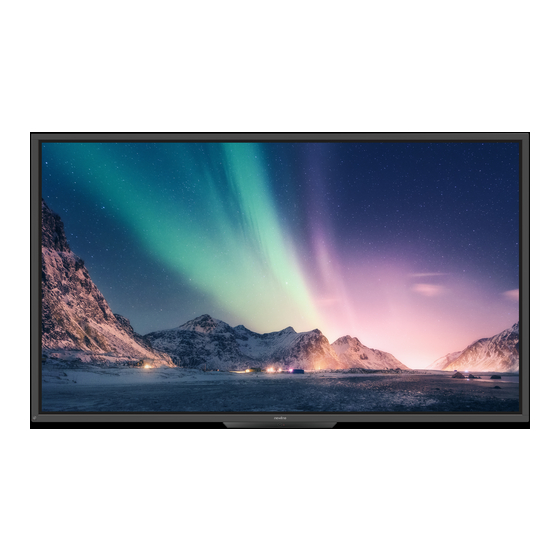
- Page 9 Front view 65/75/86 inch:...
-
Page 10: Rear View
Rear view 65/75/86 inch: Touch screen Power socket Light sensor Power switch Power button Speaker IR receiver Rear port 1 Bottom plastic part Rear port 2 Microphone OPS Computer slot Camera SoundBar port Camera indicator... -
Page 11: Front Buttons
1.2 Front Buttons Name Function description Power on/off. Turn on: press it to turn on the display, the power indicator will turn to green. Turn off: press it to shut down. The power indicator will turn to red. Note: Press the power button in the power-on state, the product enter shut down mode by default. -
Page 12: Rear Ports
1.3 Rear Ports USB 3.0/USB 2.0 ports switch connections based on signal sources. If the current signal source is reading the data from an external storage connecting to the port, please switch the signal source after the data reading is complete. Otherwise, the data or product may be damaged. - Page 14 Name Function description Microphone input port Audio input port, used in combination with “VGA In”. Audio in VGA in VGA signal input port. Used in combination with “Touch USB 3.0” to operate the PC in touch mode. HDMI 1 in HDMI signal input port 1.
- Page 15 Name Function description Connect to TS series Soundbar(optional) Warning: Soundbar TS Series Soundbar Connector port only use for TS series Soundbar. The manufacture cannot be responsible for the possible damage caused by connecting to other devices.
-
Page 16: Remote Control
1.4 Remote Control 1.4.1 Remote Control Buttons... - Page 17 Button Function Power on/off. Return to home source External Operate the external device(Automatic learning function) device ^v<> Up/Down/Left/Right selection button. Confirm button. Mute or unmute. Microphone mute or unmuted. Press once to return to the previous page; Press twice to exit the current program. Note: In the settings page, press once to exit.
- Page 18 1.4.2 Remote Control Usage Instructions To avoid potential malfunctions, please read the following instructions and use the remote control appropriately. Do not drop or smack the remote control. Do not spill liquids on the remote control. Do not place the remote control on a wet object. Do not expose the remote control to direct sunlight or other heat sources.
- Page 19 Installation Guide 2.1 Safety Precautions Environment Direction...
-
Page 20: Installation Precautions
2.2 Installation Precautions Load Bearing You can select moveable installation or wall mounting according to your own needs. Wall mounting can help users significantly reduce occupied space. When using moveable installation, use the mobile stand specified by the manufacturer. If you use a self-made mounting bracket, its carrying capacity should be at least 4 times the actual carrying weight. - Page 21 • Attaching the VESA Mounting Bracket. This apparatus is intended to be supported by a GS Listed wall- mount bracket. Ventilation Distance from mounting surface (mm) Left and right Bottom Rear sides Caution In addition to the above requirements, the area of the bottom, side and top vents should not ...
- Page 22 2.3 OPS Computer Installation Do not perform the following on the OPS Computer, or the product may be damaged or end up being unusable! Do not plug or unplug the OPS Computer with power connected. Please make sure that the ...
- Page 23 Step 3. Pass the fixing screws through the upper and lower lugs and tighten them. If the screen fuzzes, flashes or if no signal is received from the OPS Computer channel after turning on the power, it means that the OPS Computer has not been properly installed. Please check it and re- install.
-
Page 24: Power On/Off
Power ON/OFF 3.1 Power on Step 1. Use AC power (100V~240V, 50Hz/60Hz) as the product power source. Make sure the power plug fully inserted and that the ground wire of the outlet is properly connected. Step 2. Turn on the rocker switch (on the rear side of the screen, next to the power socket) after a power source has been connected. -
Page 25: Power Off
Step 3. Press the “ ” button on the product or the “ ” button on the remote control to start the product (the indicator light turns green). 3.2 Power off Step 1. Power off the screen in the following situations: If there is no whiteboard data or screenshot(s), press the power button on the front ... - Page 26 Step 3. In the Warning dialog box, click Cancel. You can save files if desired. After files are saved, return to Step 2. Click Confirm, and the power indicator will turn to red. Step 4. If you want to completely turn off the product, turn off the rocker switch under the product (next to the power socket) and unplug the power cord.
-
Page 27: Operating The Touch Screen
Operating the Touch Screen 4.1 Home When the product is turned on, the product will show the Home page, as shown in the following figure: 1: Logo (Shortcut to Settings) 2: Clock (Shortcut to Clock) 3: Date and Week(Shortcut to Calendar) 4: Side Toolbar 5: Status Bar and Settings 6: Main Icon (Dock) -
Page 28: Main Icons
HDMI 2, VGA, Type C, Newline cast and Files. Whiteboard takes you to the whiteboard function and screen annotation functions. Click “Newline Cast” to enable the wireless screen sharing function. Switch to the VGA source Click File viewer to open the File Manager to explore internal and external files on the display. -
Page 29: Side Toolbar
Note: Users can add or remove main icons as your need (OPS, Sources, whiteboard are defaults). More details refer to 5.1 Add Shortcuts to Dock. Side Toolbar Home, Annotation Mode, Whiteboard, Sources, Return, Gadget and Task manager icons are displayed by default in the sidebar on both sides of the screen. - Page 30 Access whiteboard mode. Click to view the external signal sources, including OPS, HDMI 1, 2, VGA, Type C, Newline Cast and Files. Return to the previous menu/Exit an app. Enter the Gadgets interface. Gadget displays all pre-installed applications. Click the icon of an application to run the application.
-
Page 31: Save Session
Status Bar and Settings The upper right corner of the home page displays working status icons (including USB drive(s), Ethernet, and Wi-Fi), Notification and system setting shortcut. Icon Functions Click to enter the Notification page(Show red dots when there is a notification). - Page 32 Note: The Save session function will only save the data generated in this meeting, the previous session data will not appear.
-
Page 33: Add Shortcut
Add Shortcut 5.1 Add Shortcuts to Dock Step 1. Long press any one of icons in the dock bar to enter the editing state. As shown in the following figure: Step 2. Click the "+" icon to enter the add Main Icon interface, users can add up to 6 icons, as shown in the following figure:... - Page 34 Step 3. At the Home page, click the shortcut icon and you can start the program/application or change to the external signal source. Note: Long press the icon to enter the edit state, the + icon will not appear when the 6 main icons are all added.
-
Page 35: Installation
5.3 Newline Assistant 5.3.1 Introduction The Newline Assistant is the tool used as a bridge between the smart system and the OPS Computer (OPS). It helps add Windows software shortcut to the gadget Page, as well as to protect USB data when switching between sources. - Page 36 Newline assistant window to the smart system. Only folders and .exe file are supported. Step 2. Click the icon in the sidebar to enter gadget interface to view all the Windows software shortcuts added by the Newline Assistant in Step 1.
-
Page 37: Quick Setting Menu
Quick Setting Menu Using two fingers to swipe up from the bottom of the screen, the Quick Settings menu will appear, click wherever outside of the menu to hide the quick setting menu. As shown in the following figure. In the quick settings menu interface, swipe left or right with your finger to switch the page, as shown in the following figure:... - Page 38 Icon Name Functions brightness Drag the slider to adjust the brightness. volume Drag the slider to adjust the volume. Toolbar Click the icon to turn on/off the toolbar. Microphone Click the icon to mute/unmute Microphone. mute Freeze Click the icon to enter/exit freeze function. Sound only Click the icon to enable sound only mode.
- Page 39 Icon Name Functions Screen Lock Click the icon to enter/exit screen lock function. User can set the temporary passkey for locking the screen. Mute Click the icon to mute or unmute. Wi-Fi Click the icon to turn on/off the Smart system Wi-Fi. Bluelight Click the icon to turn on/off the blue light filter.
- Page 40 For more product information, please visit https://newline-interactive.com +1 888 233 0868 National Service Hotline: The company is committed to product updates and technical improvements. The technical parameters and specifications are subject to change without prior notice. The pictures in this...
Need help?
Do you have a question about the HO Series and is the answer not in the manual?
Questions and answers